

STIEBEL ELTRON WPL 13 basic, WPL 20 basic, WPL 18 S basic, WPL 13 S basic Operation And Installation
OPERATION AND INSTALLAT ION
Air source heat pump
» WPL 13 basic
» WPL 20 basic
» WPL 13 S basic
» WPL 18 S basic

CONTENTS
SPECIAL INFORMATION
OPERATION
1. General information �����������������������������������������3
1.1 Further applicable documents �������������������������������� 3
1.2 Safety instructions ����������������������������������������������� 3
1.3 Other symbols in this documentation ����������������������� 4
1.4 Units of measurement ������������������������������������������ 4
1.5 Standardised output data �������������������������������������� 4
2. Safety ���������������������������������������������������������� 4
2.1 Intended use ������������������������������������������������������ 4
2.2 General safety instructions ������������������������������������ 4
2.3 Test symbols ������������������������������������������������������ 4
3. Appliance description ���������������������������������������4
3.1 Function ����������������������������������������������������������� 5
4. Settings �������������������������������������������������������5
5. Maintenance and care ���������������������������������������5
6. Troubleshooting ����������������������������������������������5
INSTALLATION
7. Safety ���������������������������������������������������������� 6
7.1 General safety instructions ������������������������������������ 6
7.2 Instructions, standards and regulations �������������������� 6
8. Appliance description ���������������������������������������6
8.1 Standard delivery ������������������������������������������������ 6
8.2 Accessories �������������������������������������������������������� 6
9. Preparations �������������������������������������������������� 6
9.1 Acoustic emissions ���������������������������������������������� 6
9.2 Minimum clearances �������������������������������������������� 7
9.3 Preparing the installation site��������������������������������� 8
9.4 Electrical installation������������������������������������������� 10
9.5 Buffer cylinder �������������������������������������������������� 10
10. Mounting ���������������������������������������������������� 10
10.1 Handling ���������������������������������������������������������� 10
10.2 Positioning ������������������������������������������������������� 10
10.3 Heating water connection ������������������������������������� 11
10.4 Flow rate, heating side ���������������������������������������� 12
10.5 Condensate drain ����������������������������������������������� 13
10.6 Checking the condensate drain ������������������������������13
10.7 2. Heat source ��������������������������������������������������� 14
10.8 Safety temperature controller for underfloor heating
system ������������������������������������������������������������14
11. Electrical connection ��������������������������������������� 14
11.1 Fitting casing components ������������������������������������ 16
11.2 Routing air hoses ����������������������������������������������� 18
11.3 Fitting air hoses ������������������������������������������������� 19
11.4 Thermally insulating the wall outlets ����������������������� 19
12. Commissioning ��������������������������������������������� 20
12.1 Checks before commissioning�������������������������������� 20
12.2 Commissioning �������������������������������������������������� 20
12.3 Settings ����������������������������������������������������������� 21
13. Taking the appliance out of use �������������������������� 22
13.1 Standby ����������������������������������������������������������� 22
13.2 Power interruption ��������������������������������������������� 22
14. Appliance handover ���������������������������������������� 22
15. Troubleshooting �������������������������������������������� 22
15.1 Elements on the IWS ������������������������������������������� 22
15.2 Cleaning the condensate drain ������������������������������� 23
15.3 Resetting the high limit safety cut-out ��������������������� 23
15.4 Fan noise ��������������������������������������������������������� 23
16. Maintenance ������������������������������������������������ 23
17. Specification ����������������������������������������������� 24
17.1 Connections and dimensions, basic external
installation ������������������������������������������������������� 24
17.2 Connections and dimensions, standard external
installation ������������������������������������������������������� 24
17.3 Connections and dimensions, internal installation ������ 25
17.4 Wiring diagram WPL basic standard appliance (3phase) ������������������������������������������������������������� 26
17.5 Wiring diagram WPL S basic (1-phase) ��������������������� 28
17.6 Output diagrams WPL 13 basic �������������������������������30
17.7 Output diagrams WPL 20 basic ������������������������������� 31
17.8 Output diagrams WPL 13 S basic ����������������������������32
17.9 Output diagrams WPL 18 S basic ���������������������������� 33
17.10 Data table �������������������������������������������������������� 34
GUARANTEE
ENVIRONMENT AND RECYCLING
2 | WPL basic | WPL S basic www.stiebel-eltron.com
SPECIAL INFORMATION | OPERATION
General information
SPECIAL INFORMATION
- The appliance may be used by children aged 8
and up and persons with reduced physical, sensory or mental capabilities or a lack of experience provided that they are supervised or they
have been instructed on how to use the appliance
safely and have understood the resulting risks.
Children must never play with the appliance. Children must never clean the appliance or perform
user maintenance unless they are supervised.
- Only use a permanent connection to the power
supply. The appliance must be able to be separated from the power supply by an isolator that
disconnects all poles with at least 3mm contact
separation.
- Maintain the minimum clearances to ensure trouble-free operation of the appliance and facilitate
maintenance work.
- Maintenance work, such as checking the electrical safety, must only be carried out by a qualified
contractor.
- We recommend an annual inspection (to establish
the current condition of the system), and maintenance by a contractor if required (to return the
system to its original condition).
- The heat pump power supply must not be interrupted, even outside the heating season. Otherwise the system is at risk from frost.
- The heat pump manager automatically switches
the heat pump to summer or winter mode.
OPERATION
1. General information
The chapters „Special Information“ and „Operation“ are intended
for both the user and qualified contractors.
The chapter entitled “Installation” is intended for qualified contractors.
Note
Read these instructions carefully before using the appliance and retain them for future reference.
Pass on the instructions to a new user if required.
1.1 Further applicable documents
Operating and installation instructions of the heat pump
manager WPM
Operating and installation instructions of all other com-
ponents in the system
1.2 Safety instructions
1.2.1 Structure of safety instructions
KEYWORD Type of risk
!
Here, possible consequences are listed that may result
from failure to observe the safety instructions.
Steps to prevent the risk are listed.
1.2.2 Symbols, type of risk
Symbol Type of risk
!
Injury
Electrocution
- If the heat pump and frost protection are completely switched off, drain the system on the
water side.
www.stiebel-eltron.com WPL basic | WPL S basic | 3
1.2.3 Keywords
KEYWORD Meaning
DANGER Failure to observe this information will result in serious
injury or death.
WARNING Failure to observe this information may result in serious
injury or death.
CAUTION Failure to observe this information may result in non-
serious or minor injury.
OPERATION
Safety
1.3 Other symbols in this documentation
Note
Notes are bordered by horizontal lines above and below
the text. General information is identified by the symbol
shown on the left.
Read these texts carefully.
Symbol
!
This symbol indicates that you have to do something. The ac-
tions you need to take are described step by step.
Damage to the appliance and environment
Appliance disposal
1.4 Units of measurement
Note
All measurements are given in mm unless stated otherwise.
1.5 Standardised output data
Explanations to determine and interpret the specified standardised
output data.
1.5.1 Standard: EN 14511
The output data specifically mentioned in text, diagrams and
technical datasheets has been calculated according to the test
conditions of the standard shown in the heading of this section.
Generally, these standardised test conditions will not fully meet
the conditions found at the installation site of the system user.
Depending on the chosen test method and the extent to which
this method deviates from the conditions defined in the norm
shown in the heading of this section, any deviations can have a
considerable impact.
Further factors that have an influence on the test values are the
measuring equipment, the system configuration, the age of the
system and the flow rates.
A confirmation of the specified output data can only be obtained
if the test conducted for this purpose is also performed in accordance with the conditions defined in the norm shown in the
heading of this section.
2. Safety
Only qualified contractors should carry out installation, commissioning, maintenance and repair of the appliance.
Contractors are responsible for adherence to all currently applicable regulations during installation and commissioning.
2.1 Intended use
The appliance is intended to heat buildings and domestic hot water
(DHW). The appliance is designed for extracting energy from the
air and utilising this energy in water-based heating systems within
the stated operating temperature range.
This appliance is designed for domestic use. It can be safely operated by untrained personnel. The appliance can also be used in a
non-domestic environment, e.g. in a small business, as long as it
is used in the same way.
Any other use beyond that described shall be deemed inappropriate. Observation of these instructions is also part of the correct use
of this appliance. Any changes or modifications to this appliance
void all warranty rights.
2.2 General safety instructions
Observe the following safety instructions and regulations.
- The electrical installation and installation of the heating circuit must only be carried out by a recognised, qualified contractor or by our customer service engineers
- Contractors are responsible for adherence to all currently applicable regulations during installation and commissioning.
- Operate the appliance only when fully installed and with all
safety equipment fitted
- Protect the appliance from dust and dirt ingress during
building work
WARNING Injury
!
The appliance may be used by children aged 8 and up
and persons with reduced physical, sensory or mental
capabilities or a lack of experience provided that they
are supervised or they have been instructed on how to
use the appliance safely and have understood the resulting risks. Children must never play with the appliance.
Children must never clean the appliance or perform user
maintenance unless they are supervised.
2.3 Test symbols
See type plate on the appliance.
3. Appliance description
The appliance is an air source heat pump that operates as a heating
heat pump. H eat is extracted from the outdoo r air at a low temperature
level, and is then transferred to the heating water at a higher level.
The heating water can be heated up to a flow temperature of 75 °C.
The appliance is equipped with an electric booster heater (DHC).
The electric booster heater is activated if the dual mode point is
not achieved in mono mode operation in order to ensure the heating operation and the availability of high DHW temperatures. In
such cases the electric booster heater is activated as an additional
heat source in mono energetic operation.
4 | WPL basic | WPL S basic www.stiebel-eltron.com
OPERATION
Settings
Further operational characteristics:
- Suitable for underfloor and radiator heating systems
- Still extracts heat from the outdoor air at – 20 °C outside
temperature
- Corrosion-protected, external casing components made from
hot-dipped galvanised sheet steel plus powder-coated finish
- Comprises all components required for operation and all
safety equipment
- Filled with non-combustible safety refrigerant
Note
The heat pump manager is required for control over the
entire heating system.
3.1 Function
Heat is extracted from the outdoor air via the heat exchanger
(evaporator) on the air side. The now evaporated refrigerant is
compressed with one or two compressors. Electrical energy is
necessary for this process. Now, the refrigerant is at a higher
temperature level and transfers the heat drawn from the air via
an additional heat exchanger (condenser) to the heating system.
During this process, the refrigerant expands again, and the cycle
begins again.
At air temperatures below approx. +7 °C, the humidity in the air
condenses as hoarfrost on the evaporator fins. This hoarfrost is
automatically defrosted. Water created from this defrosting collects in the defrost pan and is drained off via a hose.
In the defrost cycle, the fan is switched OFF and the heat pump
circuit is reversed. The heat required for defrosting is drawn from
the buffer cylinder.
The heat pump automatically reverts to heating mode at the end
of the defrost cycle.
4. Settings
The appliance is controlled by means of the WMP II heat pump
manager; no other control unit is required.
Observe the heat pump manager operating and installation
instructions.
6. Troubleshooting
Fault Cause Remedy
There is no hot
water or the
heating system
stays cold.
Water is leaking
from the appliance.
Indoor installation: Condensate
is collecting on
the outside of the
appliance or the
air hoses.
Outdoor installation: Condensate
is collecting on
the outside of the
appliance.
If you cannot remedy the fault, notify your qualified contractor.
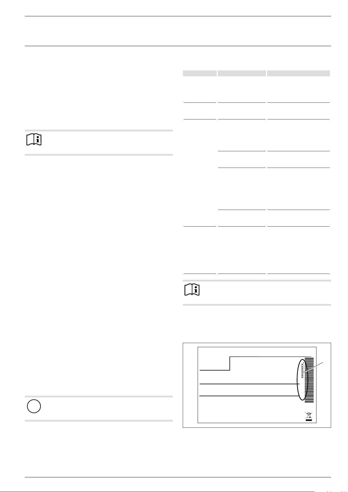
To facilitate and speed up your enquiry, please provide the serial
number from the type plate.
Sample type plate
There is no voltage at the
appliance.
The condensate drain
may be blocked.
The drying out phase of
the building is not yet
complete.
The humidity in the air is
relatively high (≥60%).
The appliance is located
in a moisture-prone
area. Moisture-prone
areas are rooms where
the humidity in the air is
high due to the drying of
laundry, for exam
ple.
The air hoses are incorrectly fitted or sealed.
Cold air escapes.
The heat pump is
drawing heat from the
outdoor air to heat the
building. This can cause
the humidity in the outdoor air to accumulate
as dew or frost on the
cooled heat pump casing.
This is not a defect.
Check the fuses/MCBs in your
fuse box/distribution panel.
If required, reset the MCBs. If
the MCBs trip again after being
reset, notify your contractor.
Clean the condensate drain as
described in chapter ‚Care and
maintenance‘.
If the room is sufficiently well
ventilated or dehumidified,
this condensate should no
longer form on the appliance approx.two years af ter the house
was built.
When the weather conditions
change, condensation should no
longer form on the appliance.
Make sure that the room is
adequately ventilated and dehumidified. If necessary, hang your
laundry up in a different room.
Use a vented tumble dryer.
Please note that condenser
tumble dryers do not reduce the
humidity in the air.
Check whether the air hoses are
correctly fitted and sealed. If
necessary, call your contractor.
Note
Even when the condensate is draining away correctly,
expect water to drip from the appliance onto the floor.
5. Maintenance and care
A damp cloth is sufficient for cleaning all plastic and sheet steel
*xxxxxxxxxxxxxxxxxx*
1
parts. Never use abrasive or corrosive cleaning agents.
Check the condensate drain monthly (visual inspection). Remove
contaminants and blockages immediately.
Damage to the appliance and environment
!
Keep the air discharge and intake apertures free from
snow and leaves.
We recommend an annual inspection (establishing the actual
state) and, if required, maintenance (returning the set state) by a
Montageanweisung beachten! Dichtheit geprüft!
1 Number on the type plate
Made in Germany
qualified contractor.
www.stiebel-eltron.com WPL basic | WPL S basic | 5
26�03�01�1736
INSTALLATION
Safety
INSTALLATION
7. Safety
7.1 General safety instructions
- Only qualified contractors should carry out installation, commissioning, maintenance and repair of the appliance.
- We guarantee trouble-free function and operational reliability only if the original accessories and spare parts intended
for the appliance are used
7.2 Instructions, standards and regulations
Note
Observe all applicable national and regional regulations
and instructions.
8. Appliance description
For external installation the appliance offers additional frost protection of the heating water pipes. The integral frost protection
circuit starts the circulation pump in the heat pump circuit automatically at +8 °C condenser temperature, and thereby ensures
circulation in all water-filled sections. The heat pump is started
automatically no later than when the temperature inside the buffer
cylinder drops below +5 °C.
Air hoses guide the intake air from the outside to the appliance and
route the discharge air from the appliance to the outside. These
are highly flexible, thermally insulated and are self-extinguishing
in case of fire in accordance with ASTMD1692-67T.
8.1 Standard delivery
8.1.1 Standard appliance
- Type plate
- Wiring diagram
8.1.2 Required accessories, external installation
The appliance casing components are supplied in a separate pack.
Description
Accessory for outdoor installation WPL .. Basic
Accessory for outdoor installation WPL 13/18/23 A
8.1.3 Required accessories, internal installation
The appliance casing components are supplied in a separate pack.
Description
Accessory for indoor installation WPL 13/18/23 I
WPIC
WPIC B
8.2 Accessories
8.2.1 Required accessories, internal and external installation
Description
Heat pump manager WPMS 3 or WPMW 3
Remote control for heating systems
Contact sensor
Immersion sensor
8.2.2 Additional required accessories for internal installation
Description
Thermally insulated air hose, 3m or 4m long
Hose connection plate
Wall outlet AWG 560
8.2.3 Further accessories
Description
Buffer cylinder
Pressure hose G 1¼ x 1 m (DN 32)
Pressure hose G 1¼ x 2 m (DN 32)
Pressure hose G 1¼ x 5 m (DN 32)
Pressure hose G 1¼ x 1 m (DN 32), can be trimmed
Hose fittings for pressure hose G 1¼ (DN 32)
Condensate pump
9. Preparations
9.1 Acoustic emissions
On the air intake and air discharge sides, the appliance is louder
than on the enclosed sides. Observe the following information
when selecting the installation location.
Note
For details regarding the sound power level, see chapter
"Specification / Data table".
9.1.1 Sound emissions for external installation
- Lawn areas and shrubs contribute to the reduction of noise.
- Noise propagation can also be reduced through dense palisades or similar.
Ensure that the air intake direction is in line with the main
wind direction. Air should not be drawn in against the wind.
Never direct the air intake or discharge towards noise-sensi-
tive rooms of the house, e.g. bedrooms.
Avoid installation on large, echoing floor areas, e.g. tiled
floors.
Avoid installation between reflective building walls. Reflec-
tive building walls can increase the sound level.
Note
Provide a recess (space) in the substrate to enable water
and electrical pipes/cables to be connected from below.
Also observe the chapter “Installation/Siting”.
6 | WPL basic | WPL S basic www.stiebel-eltron.com
INSTALLATION
Preparations
9.1.2 Sound emissions for internal installation
Never install the appliance directly below or next to living rooms
or bedrooms.
Never install on joists.
Isolate the installation surface. See chapter “Preparing the
installation site for internal installation”.
Connect the heating flow and return using flexible pres-
sure hoses. Suitable pressure hoses can be found in chapter
“Accessories”.
Insulate all pipe fixings and wall outlets against structure-
borne noise transmission.
Never direct the air intake and discharge apertures in exter-
nal walls towards neighbouring windows or living rooms/
bedrooms.
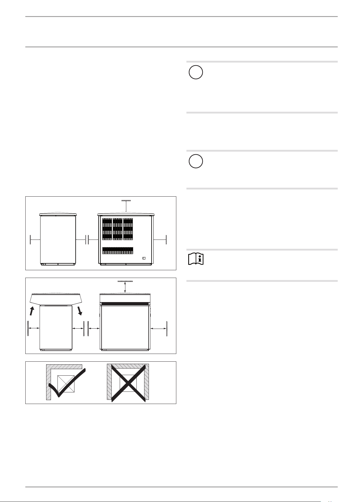
9.2 Minimum clearances
9.2.1 External installation
≥700
≥500 ≥500≥500
≥1000
Damage to the appliance and environment
!
Please note that the outdoor air must be able to flow
unimpeded into the appliance, and the exhaust air must
be able to be expelled without obstruction.
If the air intake and discharge of the appliance are obstructed by surrounding objects, this may cause a thermal
short-circuit.
Ensure that the appliance is not surrounded by any objects
such as buildings, walls or fences.
If necessary, maintain a greater clearance to the surrounding
objects.
Damage to the appliance and environment
!
The air flow rate through the appliance must not fall
below the minimum level. If the air flow rate falls below
the minimum level, trouble-free operation of the appliance is not guaranteed.
Ensure that the minimum air flow rate is maintained. Ob-
serve the details in chapter “Specification / Data table”.
If necessary, maintain a greater clearance to the surrounding
objects.
If the air discharge side of the appliance faces a wall of the house,
condensate may form on this wall from the cool air at the air
discharge.
≥700
≥500
≥500
Do not install the appliance in a recess. Two sides of the ap-
pliance must remain exposed.
Maintain the minimum clearances to ensure trouble-free op-
eration of the appliance and facilitate maintenance work.
In order to prevent air “short circuits”, maintain the mini-
mum clearances in the case of surrounding structures and
in particular in the case of cascades. Maintain the flow rate
on the heat source side (see chapter “Specification / data
table“).
≥500
≥1000
Note
D0000019239
D0000019241
91�00�00�0036
If the air discharge side faces house walls, maintain a
minimum clearance of 2m between the appliance and
the building.
www.stiebel-eltron.com WPL basic | WPL S basic | 7
INSTALLATION
3
Preparations
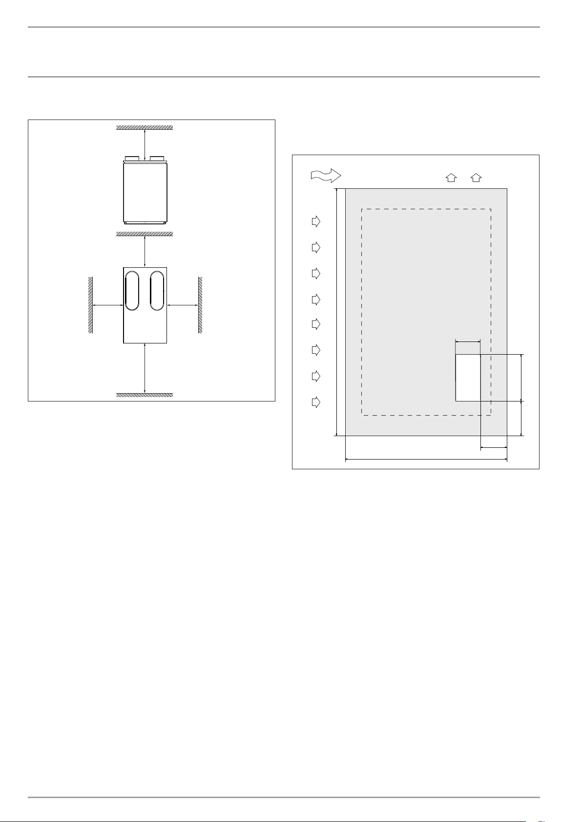
9.2.2 Internal installation
≥500
≥500
≥500
≥1000
≥500
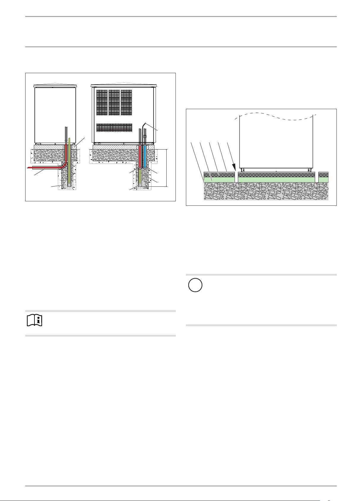
9.3.2 Preparing the installation site for external installation
Observe chapter “Sound emissions for external installation”.
Example: Foundations with recess
2
1
1440
150
4
D0000019242
300
Maintain the minimum clearances to ensure trouble-free op-
eration of the appliance and facilitate maintenance work.
9.3 Preparing the installation site
9.3.1 General information
Ensure that the appliance is accessible from all sides.
- The substrate must be horizontal, level, solid and permanent.
Observe the minimum clearances in chapter “Preparations/
Minimum clearances”.
Ensure the entire heat pump frame is in contact with the sub-
strate. Uneven substrates can increase sound emissions.
190
170
1000
D0000019240
1 Air intake
2 Air discharge
3 Main wind direction
4 Recess
8 | WPL basic | WPL S basic www.stiebel-eltron.com
INSTALLATION
6
Preparations
Example: Routing pipes underground
8
4
3
5
A Frost level
1 Heating circuit flow
2 Heating circuit return
3 Conduit for supply lines
4 Foundation
5 Gravel bed
6 Drainage pipe
7 Condensate hose
8 Electrical cables/leads
Use only cables suitable for outdoor use.
Protect the flow and return pipes against frost with sufficient
thermal insulation. Provide thermal insulation in accordance
with applicable regulations.
Protect all supply lines against humidity, damage and UV ra-
diation by means of a conduit.
Note
When routing the condensate hose, observe the chapter
“Installation / condensate drain”.
1
2
7
9.3.3 Preparing the installation site for internal installation
Observe chapter “Sound emissions for internal installation”.
Isolate the mounting surface around the heat pump by re-
cesses. After completing the installation, seal these recesses
with a water-impervious and sound insulating material, such
as silicone for example.
1 2 3 54
A
D0000019238
1 Concrete base
2 Impact sound insulation
3 Floating screed
4 Floor covering
5 Recess
In chapter “Specification/Connections and dimensions, internal
installation”, the location and dimensions of the air intake and
discharge apertures as well as those of the outlets/entries for
water pipes and cables in the appliance cover can be seen.
Material losses
!
The floor of the installation room must be water resistant.
During appliance operation, the outdoor air releases up
to 50l of condensate per day. If the condensate drain is
not installed correctly or if maintenance is not carried out
properly, water may escape. We recommend installing a
drain in the floor of the installation room.
26�03�01�1466
www.stiebel-eltron.com WPL basic | WPL S basic | 9
INSTALLATION
Mounting
9.4 Electrical installation
DANGER Electrocution!
Carry out all electrical connection and installation work
in accordance with national and regional regulations.
DANGER Electrocution!
Only use a permanent connection to the power supply.
The appliance must be able to be separated from the
power supply by an isolator that disconnects all poles
with at least 3mm contact separation. This requirement
can be met by contactors, isolators, fuses etc.
Note
The specified voltage must match the mains voltage. Observe the type plate.
Route cables with the following cross-sections in accordance with
the respective fuse rating:
Fuse rating Cable cross-section
C 16 A
C 25 A 6.0 mm² for routing through a wall
C 35 A 6.0 mm² for routing multi-core cables on a wall or in an
The electrical specifications are given in the “Data table”. The BUS
cable requires a cable J-Y (St) 2x2x0.8mm².
2.5 mm²
1.5 mm² with only two live cores and routing on a wall or in
an electrical conduit on a wall
4.0 mm² for routing multi-core cables on a wall or in an
electrical conduit on a wall
electrical conduit on a wall
10.2 Positioning
10.2.1 General information
Undo the fixing screws on the appliance frame and keep
them safe. Two or four screws are provided in the frame
to secure the cover. One screw respectively is provided to
secure the side panels (see also chapter “Fitting the casing
components”).
Note
Fit the casing components only after the electrical and
hydraulic connections have been made.
10.2.2 Internal installation
Position the standard appliance on the prepared substrate.
1
2
4
Note
Provide separate fuses/MCBs for the 3 power circuits of
the appliance, the control unit and the electric booster
heater.
9.5 Buffer cylinder
A buffer cylinder is recommended to ensure trouble-free appliance
operation. The buffer cylinder not only provides hydraulic separation of the volume flow in the heat pump and heating circuit, but
also serves as an energy source for defrosting the evaporator.
10. Mounting
10.1 Handling
Pay attention to the appliance’s centre of mass when trans-
porting the appliance.
The centre of mass is located in the compressor area.
- Lifting slings for transporting the standard appliance can be
hooked in anywhere on the lower frame.
Protect the appliance against heavy impact during transport.
- Only allow the appliance to be tilted during transport for a
short time to one of its longitudinal sides.
The longer the appliance is tilted, the greater the distribution
of refrigerant oil in the system. Wait approx. 30 minutes before starting the appliance after it has been tilted.
3
3
26�03�01�1650�
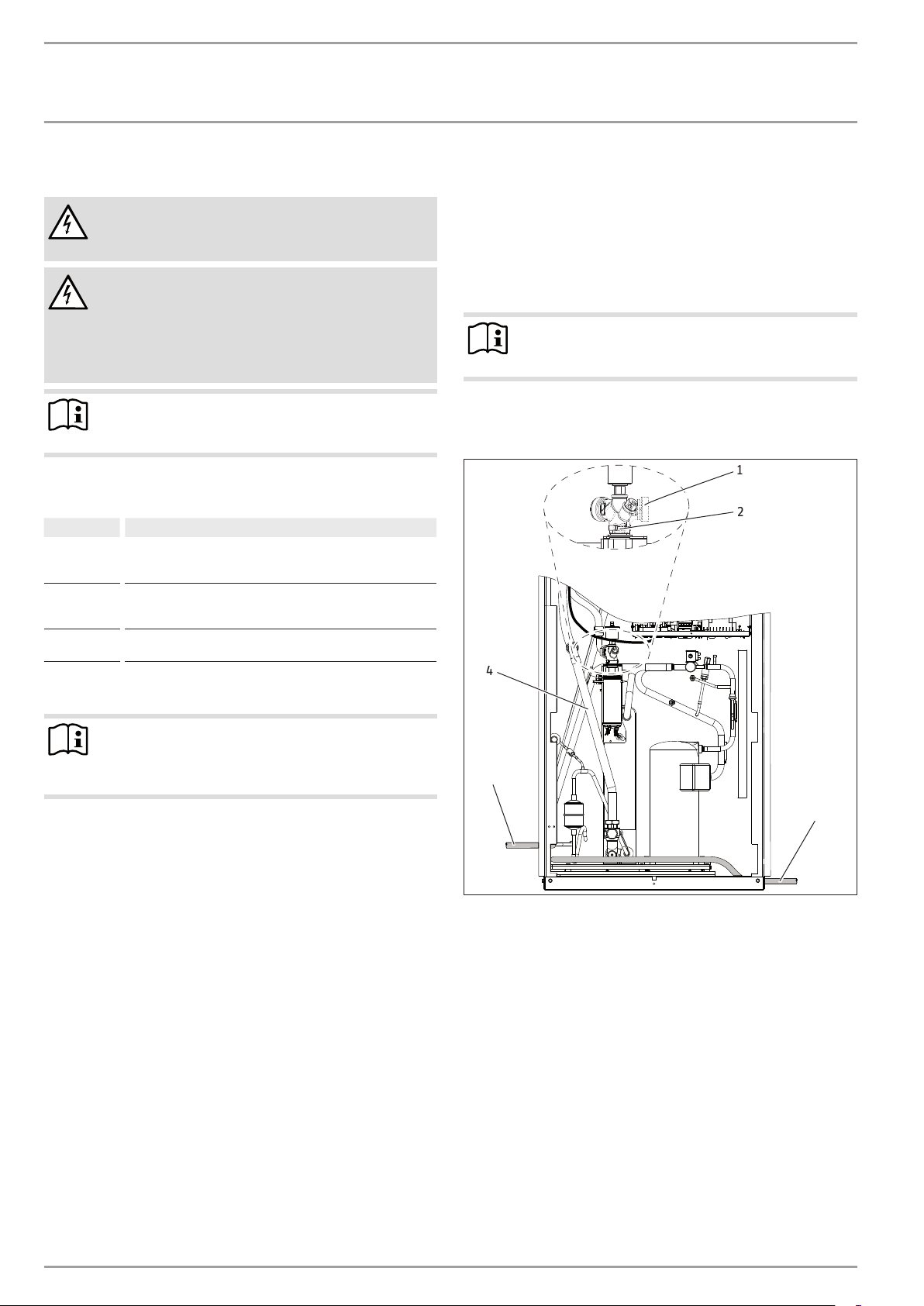
1 Connector
2 Union nut
3 Pipe bend, heating circuit return
4 Condensate drain hose
Undo the union nut from the heating flow.
Rotate the connector approx. 145°.
Retighten the union nut.
Fit the pipe bend for the heating circuit return (part of the
“Internal installation accessories”).
Route the condensate hose out of the appliance, either on the
r.h. or the l.h. side.
10 | WPL basic | WPL S basic www.stiebel-eltron.com
INSTALLATION
Mounting
1
5
2
6
3
4
1 Appliance power cable
2 Electric booster heater power cable
3 Control cable
4 BUS cable
5 Heating flow
6 Heating return
Position the cover on the appliance, and secure it with two
screws.
Cut the pipe outlets for the water pipes out of the cover.
Route the water pipes through the cover into the appliance.
Then route the cables from above through the cable entries
with strain relief fittings (PG fittings) into the appliance.
The open PG fittings are intended for the following: Appliance power supply, control cable and BUS cable.
10.2.3 External installation
Observe the air discharge direction.
Position the standard appliance on the prepared substrate.
Material losses
!
Rodents may get into the appliance through the knockout aperture.
Close off the knock-out aperture.
10.3 Heating water connection
The heating system to which the heat pump is to be connected
must be installed by a qualified contractor in accordance with the
26�03�01�0170
water installation drawings that are part of the technical documents.
Thoroughly flush the pipework before connecting the heat
pump. Debris, such as rust, sand and sealant, can impair the
operational reliability of the heat pump.
Connect the heat pump on the heating water side. Check for
tightness.
Connect flexible pressure hoses to the connectors; these will
act as anti-vibration dampers.
The pressure hoses should be at least 1 m long.
10.3.1 Oxygen diffusion
Material losses
!
Avoid open heating systems and plastic pipes in underfloor heating systems which are permeable to oxygen.
In underfloor heating systems with plastic pipes that are permeable to oxygen and in open vented heating systems, oxygen
diffusion may lead to corrosion on the steel components of the
heating system (e.g. on the indirect coil of the DHW cylinder, on
buffer cylinders, steel heating elements or steel pipes).
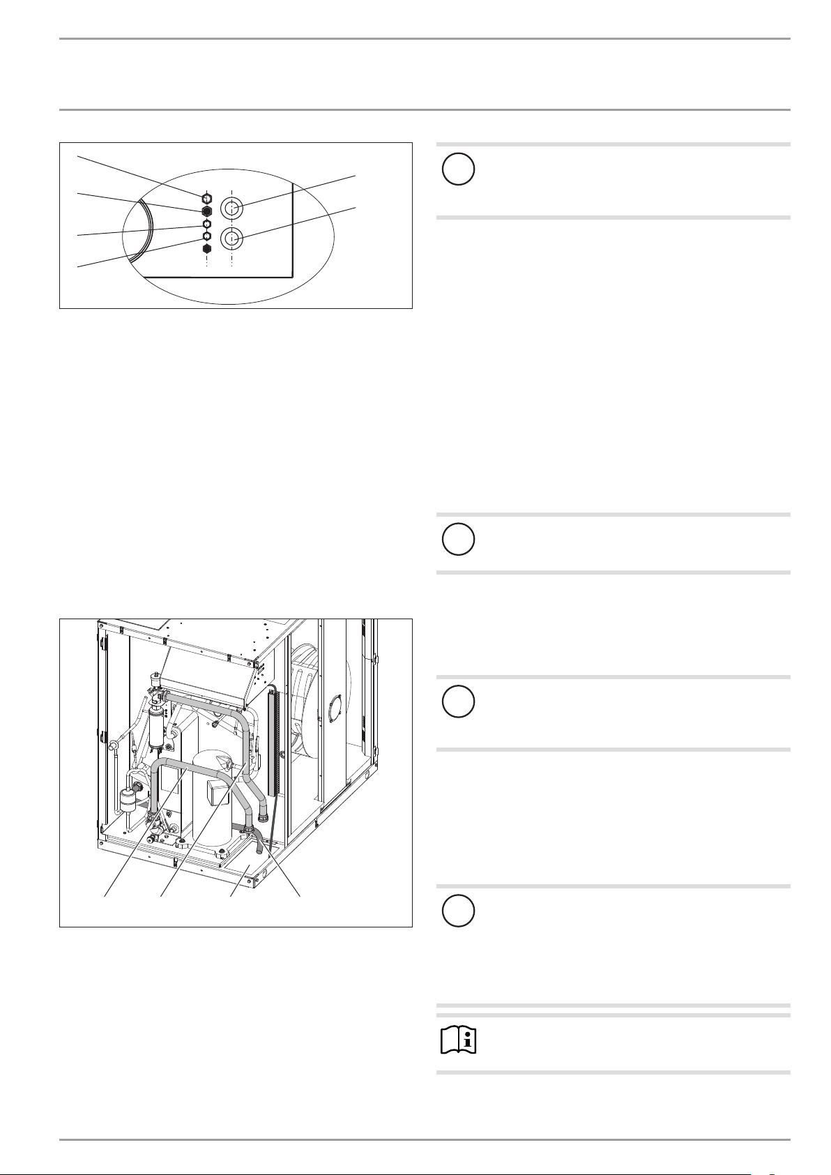
234
1 Condensate hose
2 Supply line outlet
3 Pipe bend, heating circuit flow
4 Pipe bend, heating circuit return
Fit the pipe bends for the heating circuit flow and return
(part of the “External installation accessories”).
Route the water pipes and the cables from below through the
cut-out in the floor into the appliance.
1
Material losses
!
The products of corrosion (e.g. rusty sludge) can settle in
the heating system components and can result in a lower
output or fault shutdowns due to reduced cross-sections.
10.3.2 Filling the heating system
Water quality
A fill water analysis must be available prior to charging the system. This may, for example, be requested from the relevant water
supply utility.
Material losses
26�03�01�1644�
!
To avoid damage as a result of scaling, it may be necessary to soften or desalinate the fill water. The fill water
limits specified in chapter "Specification / Data table"
must always be observed.
Recheck these limits 8-12 weeks after commission-
ing and as part of annual system maintenance.
Note
With conductivity of >1000μS/cm, desalination treatment
is recommended in order to avoid corrosion.
www.stiebel-eltron.com WPL basic | WPL S basic | 11

INSTALLATION
Mounting
Note
Suitable appliances for water softening and desalinating,
as well as for charging and flushing heating systems, can
be obtained via trade suppliers.
Note
If you treat the fill water with inhibitors or additives, the
same limits as for desalination apply.
Venting the heating system
1
1 Air vent valve
Vent the pipework carefully. For this, also activate the air
vent valve integrated into the heating flow inside the heat
pump.
10.4 Flow rate, heating side
Minimum flow rate with single room control via FE7orFEK
Maximum temperature differential on the heating side with overflow valve or single room control with remote control
12
10
8
6
4
2
0
-15 -10 -5 0 5 10 15 20 25 30
X Outside temperature [°C]
Y Maximum temperature differential [K]
In this case, one or more heating circuits in the heating system
must be left open. The open heating circuit(s) should be installed
in the lead room (room in which the remote control is installed,
e.g. the living room). Single room control can then be carried
out with the remote control or indirectly by matching the heating
curve.
Fully open the heating circuit(s) in the lead room.
Close all other heating circuits.
If an overflow valve is installed in the heating system, close
26�03� 01�1638�
this fully before determining the minimum flow rate.
Make the settings at the circulation pump when the tempera-
ture differential between the flow and return temperature
has stabilised.
Set the heating circuit pump so that the minimum flow rate required to operate the system is safeguarded.
84�03�01�0172
10.4.1 Minimum flow rate for operation without a buffer
cylinder
The appliance is designed in such a way that no buffer cylinder
is required to provide hydraulic separation of the flow in the heat
pump circuit and the heating circuit in conjunction with space
heating systems.
In an installation with several heating circuits, we recommend
using a low loss header.
The minimum flow rate is set via the temperature differential of
the heating system.
Set the heating circuit pump so that the value is equal to or lower
than the maximum temperature differential.
The setting is made in heat pump operation alone. For this, the
following settings must be carried out first:
Temporarily remove the fuse from the electric emergency/
booster heater to isolate it from the power supply. Alternatively, switch OFF the second heat source.
Operate the heat pump in heating mode.
Note
Never adjust the flow rate of the cylinder primary pump.
The flow rate of the cylinder primary pump has been
optimised at the factory.
Compare the resulting temperature differential between the
flow and return at the appliance with the diagram “Maximum
temperature differential on the heating side with overflow
valve or single room control with remote control”.
Set the heating circuit pump so that the value is equal to or
lower than the maximum temperature differential.
12 | WPL basic | WPL S basic www.stiebel-eltron.com

INSTALLATION
Mounting
10.4.2 Flow rate with low loss header or buffer cylinder
The flow rate can be adjusted using the temperature differential
of the buffer circuit. The value must not fall below the minimum
flow rate.
Maximum temperature differential on the heating side with low
loss header or buffer cylinder
12
10
8
6
4
2
0
-15 -10 -5 0 5 10 15 20 25 30
X Outside temperature [°C]
Y Maximum temperature differential [K]
Make the settings at the circulation pump when the tempera-
ture differential between the flow and return temperature
has stabilised.
Compare the resulting temperature differential between the
flow and return at the appliance with the diagram “Maximum
temperature differential on the heating side with low loss
header or buffer cylinder”.
Set the delivery head of the heating circuit pump to a level
that safeguards the heating flow rate required to operate the
heat pump (see chapter “Specification / Data table”).
If the appliance will be used for DHW heating, check the set-
ting of the delivery head in DHW mode.
If necessary, adjust the setting of the delivery head to match
the heating circuit pump.
10.4.3 Using highly energy efficient pumps
If you use a highly energy efficient pump as the heating circuit
pump, you will have to adjust the minimum flow rate using the
temperature differential of the heating system.
Set the heating circuit pump to ∆p-constant.
Set ∆p-constant to the value at which the maximum temper-
ature differential of the heating system is reached.
When connecting the electric emergency/booster heater (DHC),
a flow sensor must be connected to the heat pump manager and
installed close to the heat pump at the heating flow.
10.5 Condensate drain
A condensate drain hose is fitted to the defrost pan to enable the
condensate to drain off. The condensate drain hose is delivered
inside the refrigeration unit.
Ensure the condensate drain hose is not kinked.
Route the hose with a continuous fall.
Use a suitable condensate pump if there is insufficient fall.
Observe the building characteristics.
If using a condensate pump, ensure that it is sized for a
pump rate of at least 6 l/min.
10.5.1 External installation
Route the condensate drain hose downwards through the
knock-out “outlet for supply pipe/cable” and out of the
appliance.
Channel the condensate into a drain or allow it to drain into a
coarse gravel soakaway. Ensure the pipework is free from the
risk of frost.
10.5.2 Internal installation
You can route the condensate drain hose to the left or right
through the knock-out “outlet for condensate drain” (see chapter
“Specification / Dimensions and connections / Internal installation”) and out of the appliance.
84�03�01�0172
1
26�03�01�0956
1 Knock-out “outlet for condensate drain”
Use pliers to break out the knock-out “outlet for condensate
drain” from the l.h. side panel.
Route the condensate drain hose to the left or right out of the
appliance.
Route the condensate into a drain.
If a bottom drain is to be used, you can drain the condensate
downwards through the “outlet for supply pipe/cable” in the bottom of the appliance.
Route the condensate drain hose diagonally through the
knock-out aperture “outlet for supply pipe/cable”.
Secure the condensate drain hose to ensure it does not slip
out of place.
Route the condensate into the bottom drain.
10.6 Checking the condensate drain
After routing the condensate drain hose, check that the condensate
can drain correctly. Proceed as follows:
Pour water onto the evaporator, which will then flow into
the defrost pan. Please note the maximum condensate drain
capacity of 6 l/min.
Check whether the water is draining off via the condensate
drain hose.
www.stiebel-eltron.com WPL basic | WPL S basic | 13

INSTALLATION
Electrical connection
10.7 2. Heat source
For dual mode systems, the heat pump must always be connected
to the return of the second heat source (for example an oil boiler).
10.8 Safety temperature controller for underfloor
heating system
Material losses
!
In case of failure, in order to prevent an excessively high
flow temperature in the underfloor heating system, we
generally recommend the use of a safety temperature
controller to limit the system temperature.
11. Electrical connection
Note
Observe the heat pump manager operating and installation instructions.
Only qualified electricians may carry out the installation in accordance with these instructions.
Permission to connect the appliance may need to be obtained from
your local power supply utility.
Observe chapter “Preparing the electrical installation”.
DANGER Electrocution
Before any work, isolate the appliance from the power
supply at the control panel.
Note
The terminals are located in the appliance control panel.
Use appropriate cables in accordance with local regulations
for all connections.
Check the function of the strain relief fittings.
Connect the circulation pump for the heat utilisation side to
the heat pump manager in accordance with the technical
documents.
For external installation, route the cables through the cable
duct provided for this purpose.
11.8.1 Electrical connection of the WPL basic (three phase)
Connection X3: Appliance and electric emergency/booster
heater (DHC)
Connect the appliance to terminal X3.
Connect the electric emergency/booster heater to terminal X3
if you want to utilise the following appliance functions:
Appliance function
Mono energetic operation
Emergency mode Should the heat pump suffer a fault that prevents its
Heat-up program
(only for underfloor
heating systems)
Pasteurisation control
Effect of the electric emergency/booster
heater
If the heat pump cannot reach the dual mode point,
the electric emergency/booster heater ensures both
the heating operation and the provision of high DHW
temperatures.
continued operation, the heating output will be covered by the electric emergency/booster heater.
The electric emergency/booster heater must provide
the drying heat in case of return temperatures <25°C.
With these low system temperatures, the drying heat
must not be provided by the heat pump, otherwise
the frost protection of the appliance can no longer be
guaranteed during the defrost cycle.
After expiry of the heat-up program, you can disconnect the electric emergency/booster heater if it is not
required for the appliance operation.
Please note that during the heat-up program, the
emergency mode cannot be selected.
The electric emergency/booster heater starts automatically when the pasteurisation control is active in order
to regularly heat the DHW to 60 °C to protect it against
the growth of legionella bacteria.
1
2
1 Cable duct
2 Control panel
For installation purposes, pull out the control panel forward
from the casing.
14 | WPL basic | WPL S basic www.stiebel-eltron.com
26�03�01�1644�

INSTALLATION
Electrical connection
Terminals X4, X2, control and LV
PE
1 Power supply (heat pump, compressor)
2 Elect. booster heater (DHC)
1
L1, L2, L3, N, PE
L1, L2, L3, N, PE
Connected
load
2.6 kW L1 N PE
3.0 kW L2 N PE
3.2 kW L3 N PE
5.6 kW L1 L2 N PE
5.8 kW L1 L3 N PE
6.2 kW L2 L3 N PE
8.8 kW L1 L2 L3 N PE
Terminal assignment
2
1
X4
26�03�01�1640�
1 Control terminals
Power supply: L, N, PE
Control inputs:
2. Heat source
Ext. ST Stand alone operation
2 LV terminal
BUS high H
BUS low L
BUS ground “+” (not connected)
2
X2
26�03�01�1641�
11.8.2 Electrical connection of the WPL S basic (single phase)
Damage to the appliance and environment
!
The compressor in the appliance can only turn in one
direction. If the appliance is not connected correctly, the
compressor remains in operation for 30 seconds then
switches off.
On the heat pump manager display, the fault message NO OUTPUT
appears.
To change the direction of the rotating field, when the power
is disconnected, swap over two phases.
Cover and seal the mains terminal (X3) when all electric ca-
bles have been connected.
Connection X3: Appliance and electric emergency/booster
heater (DHC)
Connect the appliance to terminal X3.
Connect the electric emergency/booster heater to terminal X3
if you want to utilise the following appliance functions:
Appliance function
Mono energetic operation
Emergency mode Should the heat pump suffer a fault that prevents its
Heat-up program
(only for underfloor
heating systems)
Pasteurisation control
Effect of the electric emergency/booster
heater
If the heat pump cannot reach the dual mode point,
the electric emergency/booster heater ensures both
the heating operation and the provision of high DHW
temperatures.
continued operation, the heating output will be covered by the electric emergency/booster heater.
The electric emergency/booster heater must provide
the drying heat in case of return temperatures <25°C.
With these low system temperatures, the drying heat
must not be provided by the heat pump, otherwise
the frost protection of the appliance can no longer be
guaranteed during the defrost cycle.
After expiry of the heat-up program, you can disconnect the electric emergency/booster heater if it is not
required for the appliance operation.
Please note that during the heat-up program, the
emergency mode cannot be selected.
The electric emergency/booster heater starts automatically when the pasteurisation control is active in order
to regularly heat the DHW to 60 °C to protect it against
the growth of legionella bacteria.
www.stiebel-eltron.com WPL basic | WPL S basic | 15

INSTALLATION
Electrical connection
Terminals X4, X2, control and LV
PE
1 Power supply (heat pump, compressor)
2 Elect. booster heater (DHC)
1
L, N, PE
L, L´, N, PE
Connected load Terminal assignment
3.0 kW L N PE
3.2 kW L´ N PE
6.2 kW L L´ N PE
2
Cover and seal the mains terminal (X3) when all electric ca-
bles have been connected.
1
X4
26�03�01�1652�
1 Control terminals
Power supply: L, N, PE
Control inputs:
2. Heat source
Ext. ST Stand alone operation
2 LV terminal
BUS high H
BUS low L
BUS ground
BUS “+” (not connected)
11.1 Fitting casing components
2
X2
26�03�01�1651�
11.1.1 Fitting the casing components for the standard external
installation
2
1
4
3
1
1 Side panel
2 Cover
3 Front panel
4 Back panel
26�03�01�0929
16 | WPL basic | WPL S basic www.stiebel-eltron.com

INSTALLATION
Electrical connection
Hook the side panels into the hooks provided on the standard
appliance and secure them with one screw each.
3
1 Bevelled edge
2 Control panel
3 Screw
Material losses
!
The cover protects the PCB from water ingress.
Install the cover with the drip edge above the PCB.
Position the cover on the appliance, and secure it with two
screws.
Hook the side panels and front and back doors onto the
standard appliance. Secure these with a screw each.
Affix the type plate supplied to the front at the top in a clearly
visible location on the r.h. or l.h. side panel of the appliance.
1
2
11.1.3 Fitting the casing components for internal installation
Before fitting the casing sections, seal the appliance by affixing
26�03�01�1738
a plastic film; this will prevent condensation forming under all
operating conditions.
The plastic film is supplied with the casing sections.
Material losses
!
The cover protects the PCB from water ingress.
Install the cover with the drip edge above the PCB.
Position the cover on the appliance, and secure it with four
screws.
Hook the front and back panels into the hooks provided on
the standard appliance and secure them with one screw
each.
Affix the type plate supplied to the front at the top in a clearly
visible location on the r.h. or l.h. side panel of the appliance.
11.1.2 Fitting the casing components for the basic external
installation
2
1
5
1 Side panel, r.h.
2 Cover
3 Front panel
4 Side panel, l.h.
5 Back panel
3
26�03�01�1456
Apply fabric tape to seal the hole at the bottom of the frame
on the l.h. side. The fabric tape is supplied with the accessory
“thermally insulated air hose”.
4
26�03� 01�1637�
26�03�01�1454
www.stiebel-eltron.com WPL basic | WPL S basic | 17

INSTALLATION
Electrical connection
Hang the film with the pre-cut holes onto the hooks on the
appliance.
Remove the backing from the adhesive strips on the frame
and on the plastic film.
Secure the plastic film by pressing it onto the appliance.
Seal the gaps around the hooks with fabric tape.
Fitting casing components
2
1
3
11.2 Routing air hoses
Note
In the case of heat pumps installed indoors, if a blower
door test to EN 13829 is to be carried out, then all apertures which are purposely provided in the building envelope must be closed or sealed off before the air hoses
are installed.
For the blower door test, seal off the heat pump’s
supply air and extract air ducts.
You can extend the air hoses by unwinding the coils. There should
be an overlap of approx. 30 cm. The total length of hoses on the
air intake and discharge side must not exceed 8 m.
26�03�01�1455
Never incorporate more than four 90° bends. The radius of the
bends must be at least 600 mm (relative to the centre line of the
hose).
Cut to size using a sharp knife. The Bowden core can be cut
with wire cutters.
Secure the air hose at approx. 1 m intervals. This prevents
the hose from sagging because of its flexibility.
Match the air hose ends to the shape of the oval connectors
on the cover and the hose connection plates. The hose connection plates are available as accessories.
4
1
1 Side panel
2 Cover
3 Front panel
4 Back panel
Position the cover on the appliance, and secure it with two
screws.
Hook the side panels and front and back doors onto the
standard appliance. Secure these with a screw each.
Affix the type plate supplied to the front at the top in a clearly
visible location on the r.h. or l.h. side panel of the appliance.
1
26�03�01�1443
2
1 Hose connection plate
2 Hose clip (oval)
3 Air hose
4 Cover
Hose connection plate dimensions
3
2
4
26�03�01�0930�
1173
302
778
687
18 | WPL basic | WPL S basic www.stiebel-eltron.com
D0000017278

INSTALLATION
Electrical connection
Damage to the appliance and environment
!
In any case, cover the external apertures with a wire
mesh. Secure the hoses against slippage.
11.3 Fitting air hoses
The example below shows the air hose connection being fitted.
26�03�01�1449
Place the sealing strip provided around the connector.
Firstly, push the outer hose slightly upwards.
Push the inner hose halfway over the connector.
26�03�01�1446
Pull the outer hose over the connector.
Secure the hose using the oval hose clip provided.
26�03�01�1447
26�03�01�1450
26�03�01�1452
26�03�01�1453
11.4 Thermally insulating the wall outlets
Cold bridges must not be able to form between the wall outlets to
be created on site and the brickwork. Provide suitable insulation
between the wall outlets and the brickwork to prevent condensate
26�03�01�1448
from forming in the brickwork.
Seal the inner hose by affixing it to the connector using the
fabric tape provided.
www.stiebel-eltron.com WPL basic | WPL S basic | 19
As an alternative you could also use the thermally insulated AWG
560 wall outlet. The AWG 560 wall outlet is available as an accessory.

INSTALLATION
Commissioning
12. Commissioning
Note
When quick start is used, the starting resistors are not
patched in.
Do not use quick start when measuring the starting
current.
A heat pump manager is required to operate the appliance. All
necessary adjustments prior to and during operation are made
on this unit.
Only heating contractors may carry out the adjustments on the
heat pump manager commissioning report, commission the appliance and instruct the owner in its use.
Commissioning is to be carried out in accordance with these installation instructions and the operating and installation instructions
of the heat pump manager. Our customer service can assist in the
commissioning, which is chargeable.
Where this appliance is intended for commercial use, the rules of
the relevant Health & Safety at Work Act may be applicable for
commissioning. For further details, check with your local authorising body.
12.1 Checks before commissioning
Before commissioning, check the following points:
12.1.1 Heating system
- Have you filled the heating system to the correct pressure,
and opened the quick-acting air vent valve?
12.1.4 High limit safety cut-out
In ambient temperatures of below -15 °C it is possible that the high
limit safety cut-out of the electrical emergency/booster heater
may trip.
Check whether the high limit safety cut-out has tripped.
1
2
26�03�01�1023�
1 High limit safety cut-out reset button
2 Electric emergency/booster heater
Reset the high limit safety cut-out by pressing the reset
button.
12.2 Commissioning
12.2.1 DIP switch (“WP-Typ”)
Open the control panel.
The IWS is located on the r.h. side.
12.1.2 Temperature sensor
- Have you correctly located and connected the outside temperature sensor and the external return temperature sensor
(in conjunction with a buffer cylinder)?
12.1.3 Power supply
- Have you correctly connected the power supply?
-
1
2
BA
BA
4
1 LEDs
2 DIP switch (WP-Typ)
3 Reset button
4 DIP switch (BA)
With the DIP switch (“WP-Typ”), you can select the various heat
pump types on the IWS.
3
26�03�01�0921�
20 | WPL basic | WPL S basic www.stiebel-eltron.com

INSTALLATION
Commissioning
Factory setting:
Compressor mode with electric emergency/booster heater
WP - Typ
ON
1 2 3 4
Check whether the DIP switch is set correctly.
Compressor mode with external second heat generator
Damage to the appliance and environment
!
In this case, do not connect the electric emergency/
booster heater.
If the appliance is operated in dual mode operation with an external second heat generator or as module with another identical
heat pump, set the DIP switches as follows:
WP - Typ
ON
Observe the WPM operating and installation instructions.
The following steps will help you to adjust the heating curve correctly:
- Fully open thermostatic or zone valves in a lead room (e.g.
living room and bathroom).
We do not recommend installing thermostatic or zone valves
in the lead room. Control the temperature for these rooms
via remote control.
- At different outside temperatures (e.g. –10°C and +10°C),
D0000057054
adjust the heating curve so the required temperature is set in
the lead room.
Standard values to begin with:
Parameter
Heating curve 0.4 0.8
Control response time
Comfort temperature
If the room temperature in spring and autumn is too low (approx.
10 °C outside temperature), the value of parameter COMFORT TEMPERATURE must be raised in the heat pump manager menu under
SETTINGS / HEATING / HEATING CIRCUIT.
Note
If no remote control is installed, raising the parameter
“COMFORT TEMPERATURE” leads to a parallel offset of
the heating curve.
Underfloor heating system
5 15
20°C 20°C
Radiator heating system
1 2 3 4
DIP switch (BA)
With the DIP switch (BA), the operating mode of the heat pump
is set.
Check whether the DIP switch is set correctly.
Damage to the appliance and environment
!
DIP switches 2, 3 and 4 must always be set to the OFF
position. The heat pump can only be operated when the
switch is in this position.
BA
ON
1 2 3 4
12.3 Settings
Increase the parameter “heating curve” if the room temperature
is not high enough when outside temperatures are low.
D0000057055
If the parameter “heating curve” has been raised, adjust the zone
valve or thermostatic valve in the lead room to the required temperature at high outside temperatures.
Material losses
!
Never reduce the temperature in the entire building by
closing all zone or thermostatic valves, instead use the
setback programs.
When everything has been implemented correctly, the system
can be heated to its maximum operating temperature and vented
once again.
Material losses
!
With underfloor heating systems, observe the maximum
permissible temperature for the system.
12.3.2 Further WPM settings
D0000057050
For operation with and without buffer cylinder, observe
chapter “Operation / Menu structure / Menu SETTINGS /
STANDARD SETTING / BUFFER OPERATION” in the operating
and installation instructions of the WPM.
12.3.1 Heating curve adjustment
The efficiency of a heat pump decreases as the flow temperature
rises. The heating curve should therefore be adjusted with care.
Heating curves that are set too high cause the zone valves and
thermostatic valves to close, which may lead to the minimum flow
rate required for the heating circuit not being achieved.
www.stiebel-eltron.com WPL basic | WPL S basic | 21
When using the heat-up program
If you use the heat-up program, make the following settings on
the WPM 3:
Initially set parameter “DUAL MODE TEMP HZG” to 30°C.
Then set parameter “LOWER APP LIMIT HZG” to 30°C.

INSTALLATION
Taking the appliance out of use
Note
After completing the heat-up process, reset the parameter “DUAL MODE TEMP HZG” and “LOWER APP LIMIT
HZG” to their respective standard values or to the respective system values.
13. Taking the appliance out of use
Damage to the appliance and environment
!
The heat pump power supply must not be interrupted,
even outside the heating season. Otherwise the system
is at risk from frost.
The heat pump manager automatically switches the heat
pump to summer or winter mode.
13.1 Standby
To take the appliance out of use, simply set the heat pump manager to “Standby mode”. That way the safety functions that protect
the system and frost protection remain enabled.
13.2 Power interruption
If the system is permanently isolated from the power supply,
please observe the following:
Damage to the appliance and environment
!
If the heat pump and frost protection are completely
switched off, drain the system on the water side.
15.1 Elements on the IWS
The IWS (integral heat pump controller II) helps you to troubleshoot if the fault cannot be identified using the WPM.
BA
BA
4
1 LEDs
2 Reset switch
3 DIP switch (HP type)
4 DIP switch (BA)
15.1.1 Checking the “HP type” DIP switch on the IWS
Check whether the “HP type” DIP switch (3) is set as follows:
With electric booster heater (DHC):
3
26�03�01�0921
14. Appliance handover
Explain the appliance function to users and familiarise them with
its operation.
Note
Hand over these operating and installation instructions
to the user for safe-keeping.
Always carefully observe all information in these instructions. They provide information on safety, operation, installation and maintenance of the appliance.
15. Troubleshooting
Note
Please observe the heat pump manager operating and
installation instructions.
Note
The following inspection instructions may only be carried
out by a qualified contractor.
If a fault cannot be located using the heat pump manager:
Open the control panel.
Read the following sections on troubleshooting and carry out
the instructions.
WP - Typ
ON
1 2 3 4
With second heat source:
If the appliance is operated in dual mode with an external
second heat source, set the DIP switch as follows:
WP - Typ
ON
1 2 3 4
In this case, do not connect the power supply for the electric
booster heater (DHC).
D0000057054
D0000057055
22 | WPL basic | WPL S basic www.stiebel-eltron.com

INSTALLATION
Maintenance
15.1.2 Checking the “BA” DIP switch on the IWS
Check whether the “BA” DIP switch (4) is set as follows:
BA
ON
1 2 3 4
15.1.3 LEDs (1)
Red LED
Fault Cause Remedy
Appliance stops and
restar ts af ter the idle
period has expired. Red
LED flashes
Appliance stops permanently. Red LED illuminates
Green LED (centre)
The LED flashes during initialisation, and illuminates constantly
after the BUS address has been assigned successfully. Only then
is communication with the WPM established.
Green LED (right)
It is constantly illuminated when STAND-ALONE mode has been
selected.
15.1.4 Reset button
If the IWS was incorrectly initialized, the settings can be reset with
this button. For this also observe the chapter “Reinitialising IWS”
in the heat pump manager operating and installation instructions.
15.2 Cleaning the condensate drain
Environmental conditions may result in the condensate drain becoming blocked. To clean the drain, proceed as follows:
DANGER Electrocution!
Before removing the casing components, disconnect all
poles from the power supply.
Remove the casing components
(see chapter “Installation”).
Check the hose and the pipe of the condensate drain.
Remove contaminants and blockages immediately.
Refit the casing components to the appliance (see chapter
“Installation/fitting casing components”).
Heat pump fault
Five faults within two
hours compressor
runtime
Check the fault message
in the WPM. Find the solution in the WPM instructions (fault list). Perform a
reset of the IWS (see WPM
instructions)
Check the fault message
in the WPM. Find the solution in the WPM instructions (fault list). Perform a
reset of the IWS (see WPM
instructions)
15.3 Resetting the high limit safety cut-out
The internal second heat source stops if the heating water temperature exceeds 85 °C, i.e. due to a low flow rate.
Remove the cause of the fault.
Reset the high limit safety cut-out. For this, press the button
shown:
1
D0000057050
2
C26�03�01�1023
1 High limit safety cut-out reset button
2 Electric emergency/booster heater (DHC)
15.4 Fan noise
The heat pump draws heat from the outdoor air. This causes the
outdoor air to cool down. At outside temperatures of 0°C to 8°C,
the air may be cooled to below freezing point. If under these
conditions precipitation occurs in the form of rain or fog, ice may
form on the air grille, the fan blades or the airways. If the fan
comes into contact with this ice, noise develops.
How to remedy rhythmic scratching or grinding noises:
Check whether the condensate drain is clear of obstructions.
Carry out a manual defrost, repeatedly if required, until the
fan runs free again.
At outside temperatures above + 1°C, switch the appliance
off for around 1hour or switch it over to emergency mode.
After this, the ice should have melted.
Check whether the appliance is installed in line with the in-
stallation conditions.
If the noises occur frequently, notify customer support.
16. Maintenance
If heat meters are installed, their sieves should be cleaned regularly.
Regularly remove all leaves and accumulated dirt from the evaporator fins, which can be accessed by removing the side a. panel
on the condenser side.
Check whether the heating water is being circulated at a sufficient
flow rate.
We recommend that you perform an annual inspection (to establish the current condition of the system), and carry out any maintenance as required (to return the system to its original condition).
www.stiebel-eltron.com WPL basic | WPL S basic | 23

INSTALLATION
Specication
17. Specification
17.1 Connections and dimensions, basic external installation
1198
i21 Supply line outlet
g01 Air intake
g02 Air discharge
894
800
1292
g01
i21 i21
1240
g02
D0000016805
17.2 Connections and dimensions, standard external installation
g01
i21 i21
g02
D0000016756
i21 Supply line outlet
g01 Air intake
g02 Air discharge
24 | WPL basic | WPL S basic www.stiebel-eltron.com

INSTALLATION
Specication
17.3 Connections and dimensions, internal installation
d44d44
1260
442
b01
195
158
g01
619
800
1240
d44
g02
133
e02
233
e01
b01 Entry electrical cables
d44 Entry condensate hose
e01 Heating flow Male thread G 1 1/4 A
e02 Heating return Male thread G 1 1/4 A
g01 Air intake
g02 Air discharge
www.stiebel-eltron.com WPL basic | WPL S basic | 25
D0000016755

INSTALLATION
A2
X29 X36
1A 2A
1A 2A
A B
A B
A B
K1
K2
K5
K6
K7
1
2
3
4
5
6
7
8
9
10
11
12
1
2
3
X38
54321
Specication
17.4 Wiring diagram WPL basic standard appliance (3-phase)
A2/X36
X23
NETZ
WP
N
L1 L2 L3 N L1 L2 L3
1 2 3 4 5 6 7 8
K1
2 4 6
K2
1 3 5
DHC
531
642
X23X23
STEUERUNG
NETZ
L N PE
X4
X3
1
K5
3
1
K6
3
R2R3
R1
X23
1
K7
3
21
K1
22
22
K2
21
1 2 3 4
X23
2.WE
Ext.St.
5
X1
1
2
3
4
5
6
N
L
M
M6
1~
C
S R
M1
M
3~
A2 Integral heat pump controller (IWS)
B1 Heat pump flow temperature sensor - KTY
B2 Heat pump return temperature sensor - KTY
B5 Hot gas temperature sensor - KTY
B6 Intake air temperature sensor - PT1000
B7 Compressor intake temperature sensor - PT1000
B8 Evaporator discharge temperature sensor - PT1000
B9 Frost protection temperature sensor - KTY
B10 Injection temperature sensor - PT1000
E1 Instantaneous water heater (DHC)
E2 Oil sump heater
F2 High pressure switch
F5 High limit safety cut-out DHC
F7 Fan temperature limiter
K1 Resistance start contactor
K2 Compressor start contactor
K5 Instantaneous water heater relay
K6 Instantaneous water heater relay
K7 Instantaneous water heater relay
M1 Compressor motor
M6 Fan motor
M7 Stepper motor el. expansion valve
N2 Differential pressure switch - defrost
X31
E1
F5
3121
11
4 3
P2=3000W
P1=2600W
12
P3=3200W
3222
Y1
2
P1 High pressure sensor
P3 Low pressure sensor
R1 Starting resistance
R2 Starting resistance
R3 Starting resistance
X1 Terminals
X2 Low voltage terminal strip
X3 Mains terminal
X4 Control terminals
X23 Power supply earth block
X29 12-pin IWS plug - control unit
X30 3-pin IWS plug - BUS
X31 DHC terminal
X33 5-pin IWS plug - el. expansion valve
X34 7-pin IWS plug - sensors
X35 6-pin IWS plug - temperature sensors
X38 3-pin IWS plug - DHC
X39 Pressure sensor terminal
X40 Temperature sensor ground terminal
Y1 Diverter valve - defrost
3
N2 F2
p >
> p
X31
1
2
E2
26�03�01�1624�
26 | WPL basic | WPL S basic www.stiebel-eltron.com

INSTALLATION
Specication
K1
K2
K5
K6
H
L 2 3 4
X2
1 2 3 4
X29 X36
1
2
3
4
5
6
7
8
9
10
11
12
X38
1
2
1A 2A
3
A2
1A 2A
A B
54321
X37
X35
X30
X34
X33
3
2
1
6
5
4
3
2
1
3
2
1
7
6
5
4
3
2
1
5
4
3
2
1
“+”
X40
X40
X39
1
rt sw ge ws
1
2
3
4
M6
A B
K7
A B
M7
M
_
T
B1
3 2 1
T
B2
3 2 1
p
P1
p
P3
T
T
B10
B9
T
T
B7
B8
T
T
B5
B6
26�03�01�1624�
www.stiebel-eltron.com WPL basic | WPL S basic | 27

INSTALLATION
A2
X29 X36
A B
K6
1
2
3
4
5
6
7
8
9
10
11
12
1
2
3
X38
432
1
A B
K2
K5
AB
Specication
17.5 Wiring diagram WPL S basic (1-phase)
A2/X36
X23
X23
K2
X23
NETZ
WP
N`
1 2 3 4 5 6
642
1 3 5
Z1
DHC
STEUERUNG
NL`LN L` L
X3
7
CSS
R
RC
L
N
ON
S
1
K5
3
1
K6
3
X23
F5
3121
11
3222
12
X31
3 4
X4
NETZ
L N PE
1 2 3 4
X23
2.WE
5
Ext.St.
X1
1
2
3
4
5
6
N
L
M
M6
1~
C
R S
M1
M
1~
A2 Integral heat pump controller (IWS)
B1 Heat pump flow temperature sensor - KTY
B2 Heat pump return temperature sensor - KTY
B5 Hot gas temperature sensor - KTY
B6 Intake air temperature sensor - PT1000
B7 Compressor intake temperature sensor - PT1000
B8 Evaporator discharge temperature sensor - PT1000
B9 Frost protection temperature sensor - KTY
B10 Injection temperature sensor - PT1000
CSS Soft start compressor
E1 Instantaneous water heater (DHC)
E2 Oil sump heater
F2 High pressure switch
F5 High limit safety cut-out DHC
F7 Fan temperature limiter
K2 Compressor start contactor
K5 Instantaneous water heater relay
K6 Instantaneous water heater relay
M1 Compressor motor
M6 Fan motor
M7 Stepper motor el. expansion valve
N2 Differential pressure switch - defrost
E1
Y1
P3=3200W
P2=3000W
P1=2600W
P1 High pressure sensor
P3 Low pressure sensor
X1 Terminals
X2 Low voltage terminal strip
X3 Mains terminal
X4 Control terminals
X23 Power supply earth block
X29 12-pin IWS plug - control unit
X30 3-pin IWS plug - BUS
X31 DHC terminal
X33 5-pin IWS plug - el. expansion valve
X34 7-pin IWS plug - sensors
X35 6-pin IWS plug - temperature sensors
X38 3-pin IWS plug - DHC
X39 Pressure sensor terminal
X40 Temperature sensor ground terminal
Y1 Diverter valve - defrost
Z1 Compressor capacitor
2
p >
3
N2 F2
> p
X31
1
2
E2
26�03� 01�1636�
28 | WPL basic | WPL S basic www.stiebel-eltron.com

INSTALLATION
Specication
H “+”
X2
1 2 3 4
L
1
2 3 4
rt sw ge ws
X29 X36
1
2
3
4
5
6
7
8
9
10
11
12
K2
AB
K5
A B
K6
A B
X38
1
2
3
A2
3
2
1
X35
6
5
4
3
2
1
X30
3
2
1
X34
7
6
5
4
3
2
1
X33
5
4
3
2
1
X37
54321
M7
X40
X39
X40
M
_
T
B1
M6
1
2
3
4
3 2 1
T
B2
3 2 1
p
P1
p
P3
T
T
B10
B9
T
T
B7
B8
T
T
B5
B6
www.stiebel-eltron.com WPL basic | WPL S basic | 29
26�03� 01�1636�

INSTALLATION
-20 -15 -10 -5 0 5 10 15 20 25 30 35 40
6
Specication
17.6 Output diagrams WPL 13 basic
Key to output diagrams
Y Heating output [kW] | Power consumption [kW] | Coefficient of performance ε [-]
X Inlet temperature of the heat source medium [°C]
1 Flow temperature 35 °C
2 Flow temperature 45 °C
3 Flow temperature 55 °C
4 Flow temperature 60 °C
Heating output
16
14
12
10
8
6
4
2
0
-20 -15 -10 -5 0 5 10 15 20 25 30 35 40
Power consumption
1
2
3
4
84�03�01�0134
6
1
4
2
3
4
2
0
-20 -15 -10 -5 0 5 10 15 20 25 30 35 40
Coefficient of performance (COP)
1
30 | WPL basic | WPL S basic www.stiebel-eltron.com
4
2
0
2
3
4
84�03�01�0135
84�03�01�0136

INSTALLATION
-20 -15 -10 -5 0 5 10 15 20 25 30 35 40
6
Specication
17.7 Output diagrams WPL 20 basic
Key to output diagrams
Y Heating output [kW] | Power consumption [kW] | Coefficient of performance ε [-]
X Inlet temperature of the heat source medium [°C]
1 Flow temperature 35 °C
2 Flow temperature 45 °C
3 Flow temperature 55 °C
4 Flow temperature 60 °C
Heating output
25
20
15
10
5
0
-20 -15 -10 -5 0 5 10 15 20 25 30 35 40
Power consumption
1
2
3
4
84�03�01�0143
8
4
0
-20 -15 -10 -5 0 5 10 15 20 25 30 35 40
Coefficient of performance (COP)
www.stiebel-eltron.com WPL basic | WPL S basic | 31
4
2
0
1
2
3
4
84�03�01�0144
1
2
3
4
84�03�01�01345

INSTALLATION
6
Specication
17.8 Output diagrams WPL 13 S basic
Key to output diagrams
Y Heating output [kW] | Power consumption [kW] | Coefficient of performance ε [-]
X Inlet temperature of the heat source medium [°C]
1 Flow temperature 35 °C
2 Flow temperature 45 °C
3 Flow temperature 55 °C
4 Flow temperature 60 °C
Heating output
16
14
12
10
8
6
4
2
0
-20 -15 -10 -5 0 5 10 15 20 25 30 35 40
Power consumption
1
2
3
4
84�03�01�0137
6
1
4
2
3
4
2
0
-20 -15 -10 -5 0 5 10 15 20 25 30 35 40
Coefficient of performance (COP)
1
4
2
0
-20 -15 -10 -5 0 5 10 15 20 25 30 35 40
32 | WPL basic | WPL S basic www.stiebel-eltron.com
2
3
4
84�03�01�0138
84�03�01�0139

INSTALLATION
-20 -15 -10 -5 0 5 10 15 20 25 30 35 40
7
Specication
17.9 Output diagrams WPL 18 S basic
Key to output diagrams
Y Heating output [kW] | Power consumption [kW] | Coefficient of performance ε [-]
X Inlet temperature of the heat source medium [°C]
1 Flow temperature 35 °C
2 Flow temperature 45 °C
3 Flow temperature 55 °C
4 Flow temperature 60 °C
Heating output
25
20
15
10
5
0
-20 -15 -10 -5 0 5 10 15 20 25 30 35 40
Power consumption
1
2
3
4
84�03�01�0140
8
4
0
-20 -15 -10 -5 0 5 10 15 20 25 30 35 40
Coefficient of performance (COP)
5
3
1
www.stiebel-eltron.com WPL basic | WPL S basic | 33
1
2
3
4
84�03�01�0141
1
2
3
4
84�03�01�0142

INSTALLATION
Specication
17.10 Data table
Output details apply to new appliances with clean heat exchangers.
The power consumption of the integral auxiliary drives is stated as a maximum and may vary, subjectto operating point.
The power consumption of the integral auxiliary drives is already included in the output details of the heat pump, as specifi ed by the
EN 14511.
WPL 13 basic WPL 20 basic WPL 13 S basic WPL 18 S basic
230385 230386 230387 230388
Heating output to EN 14511
Heating output at A-7/W35 (EN 14511) kW 6.39 10.43 6.69 8.89
Heating output at A2/W35 (EN 14511) kW 8.5 12.9 9.07 11.6
Heating output at A7/W35 (EN 14511) kW 10.69 15.17 10.86 13.62
Heating output at A10/W35 (EN 14511) kW 11.76 18 11.82 16.10
Power consumption
Power consumption, fan heating max. kW 0.13 0.13 0.13 0.13
Power consumption, emergency/booster heater kW 8.8 8.8 6.2 6.2
Power consumption to EN 14511
Power consumption at A-7/W35 (EN 14511) kW 2.19 3.69 2.34 3.93
Power consumption at A2/W35 (EN 14511) kW 2.35 3.84 2.48 3.42
Power consumption at A7/W35 (EN 14511) kW 2.43 3.96 2.57 3.51
Power consumption at A10/W35 (EN 14511) kW 2.43 4.1 2.59 3.56
COP to EN 14511
COP at A-7/W35 (EN 14511) 2.92 2.82 2.86 2.26
COP at A2/W35 (EN 14511) 3.62 3.36 3.66 3.39
COP at A7/W35 (EN 14511) 4.4 3.83 4.23 3.88
COP at A10/W35 (EN 14511) 4.84 4.39 4.56 4.52
Sound data
Sound power level outdoor installation (EN 12102) dB(A) 68 70 70 73
Sound power level indoor installation, air intake/discharge (EN 12102) dB(A) 62 64 62 62
Sound power level indoor installation (EN 12102) dB(A) 56 58 56 57
Application limits
Min. application limit on the heating side °C 15 15 15 15
Max. application limit on the heating side °C 60 60 60 60
Min. application limit, heat source °C -18 -18 -18 -18
Max. application limit, heat source °C 40 40 40 40
Water hardness °dH ≤3 ≤3 ≤3 ≤3
pH value (with aluminium compounds) 8.0-8.5 8.0-8.5 8.0-8.5 8.0-8.5
pH value (without aluminium compounds) 8.0-10.0 8.0-10.0 8.0-10.0 8.0-10.0
Chloride mg/l <30 <30 <30 <30
Conductivity (softening) μS/cm <1000 <1000 <1000 <1000
Conductivity (desalination) μS/cm 20 -10 0 20-100 20-100 20-100
Oxygen 8-12 weeks after filling (softening) mg/l <0.02 <0.02 <0.02 <0.02
Oxygen 8-12 weeks after filling (desalination) mg/l <0.1 <0.1 <0.1 <0.1
Energy data
Energy efficiency class, average climate, W55/W35 A+/A+ A+/A+ A+/A+ A+/A+
Electrical data
Compressor fuse/MCB A 3 x C 16 3 x C 16 1 x C 25 1 x C 25
MCB/fuse protection, controller A 1 x B 16 1 x B 16 1 x B 16 1 x B 16
MCB/fuse protection, emergency/booster heater A 3 x B 16 3 x B 16 1 x B 16 1 x B 16
Frequency Hz 50 50 50 50
Phases, compressor 3/N/PE 3/N/PE 1/N/PE 1/N/PE
Phases, controller 1/N/PE 1/N/PE 1/N/PE 1/N/PE
Phases, emergency/booster heater 3/N/PE 3/N/PE 1/N/PE 1/N/PE
Starting current (with/without starting current limiter) A 21/- 25/- <45/89 <45/89
Rated voltage, compressor V 400 400 230 230
Rated voltage, controller V 230 230 230 230
Rated voltage, emergency/booster heater V 400 400 230 230
Versions
Condenser material 1.4401/Cu 1.4401/Cu 1.4401/Cu 1.4401/Cu
Refrigerant R407 C R407 C R407 C R407 C
Refrigerant charge kg 2.65 2.7 2.56 2.65
Defrost type Circuit reversal Circuit reversal Circuit reversal Circuit reversal
IP rating IP14B IP14B IP14B IP14B
34 | WPL basic | WPL S basic www.stiebel-eltron.com

INSTALLATION | GUARANTEE | ENVIRONMENT AND RECYCLING
Guarantee
The guarantee conditions of our German companies do not
apply to appliances acquired outside of Germany. In countries
where our subsidiaries sell our products a guarantee can only
be issued by those subsidiaries. Such guarantee is only grant-
ed if the subsidiary has issued its own terms of guarantee. No
other guarantee will be granted.
We shall not provide any guarantee for appliances acquired in
countries where we have no subsidiary to sell our products.
This will not aect warranties issued by any importers.
Environment and recycling
Specication
WPL 13 basic WPL 20 basic WPL 13 S basic WPL 18 S basic
Dimensions
Height mm 1116 1116 1116 1116
Width mm 784 784 784 784
Depth mm 1182 1182 1182 1182
Height (outdoor installation) mm 1214 1214 1214 1214
Width (outdoor installation) mm 800 800 800 800
Depth (outdoor installation) mm 1240 1240 1240 1240
Height (indoor installation) mm 1182 1182 1182 1182
Width (indoor installation) mm 800 800 800 800
Depth (indoor installation) mm 1240 1240 1240 1240
Weights
Weight kg 205 220 205 220
Total weight - outdoor installation kg 230 245 230 245
Total weight - internal installation kg 215 230 215 230
Connections
Connection on the heating side G 1 1/4 G 1 1/4 G 1 1/14 G 1 1/14
Values
Heating flow rate (EN 14511) at A7/W35, B0/W35 and 5 K m³/h 1.84 2.84 1.83 2.62
Min heating flow rate m³/h 1 1.4 0.78 1.07
Nominal heating flow rate at A2/W35, B0/W35 and 7 K m³/h 1.05 1.62 1.12 1.52
Flow rate, heat source side m³/h 3500 3500 3500 3500
Total available external pressure differential hPa 1.0 1.0 1.0 1.0
Max. available external pressure differential, inlet side hPa 0.8 0.8 0.8 0.8
Internal pressure differential hPa 70 200 70 190
Guarantee
The guarantee conditions of our German companies do not
apply to appliances acquired outside of Germany. In countries
where our subsidiaries sell our products a guarantee can only
be issued by those subsidiaries. Such guarantee is only granted if the subsidiary has issued its own terms of guarantee. No
other guarantee will be granted.
We shall not provide any guarantee for appliances acquired in
countries where we have no subsidiary to sell our products.
This will not aect warranties issued by any importers.
www.stiebel-eltron.com WPL basic | WPL S basic | 35
We would ask you to help protect the environment. After use,
dispose of the various materials in accordance with national
regulations.
KYOTO | R407C
This device is filled with refrigerant R407C.
Refrigerant R407C is a CFC greenhouse gas mentioned in the Kyoto
protocol with a global greenhouse potential (GWP) = 1653.
Never release refrigerant R407C to atmosphere.

g
y
Deutschland
STIEBEL ELTRON GmbH & Co. KG
Dr.-Stiebel-Straße 33 | 37603 Holzminden
Tel. 05531 702-0 | Fax 05531 702-480
info@stiebel-eltron.de
www.stiebel-eltron.de
Australia
STIEBEL ELTRON Australia Pty. Ltd.
6 Prohasky Street | Port Melbourne VIC 3207
Tel. 03 9645-1833 | Fax 03 9645-4366
info@stiebel.com.au
www.stiebel.com.au
Austria
STIEBEL ELTRON Ges.m.b.H.
Eferdinger Str. 73 | 4600 Wels
Tel. 07242 47367-0 | Fax 07242 47367-42
info@stiebel-eltron.at
www.stiebel-eltron.at
Belgium
STIEBEL ELTRON bvba/sprl
't Hofveld 6 - D1 | 1702 Groot-Bijgaarden
Tel. 02 42322-22 | Fax 02 42322-12
info@stiebel-eltron.be
www.stiebel-eltron.be
China
STIEBEL ELTRON (Guangzhou) Electric
Appliance Co., Ltd.
Rm 102, F1, Yingbin-Yihao Mansion, No. 1
Yingbin Road
Panyu District | 511431 Guangzhou
Tel. 020 39162209 | Fax 020 39162203
info@stiebeleltron.cn
www.stiebeleltron.cn
Czech Republic
STIEBEL ELTRON spol. s r.o.
K Hájům 946 | 155 00 Praha 5 - Stodůlky
Tel. 251116-111 | Fax 235512-122
info@stiebel-eltron.cz
www.stiebel-eltron.cz
Finland
STIEBEL ELTRON OY
Kapinakuja 1 | 04600 Mäntsälä
Tel. 020 720-9988
info@stiebel-eltron.fi
www.stiebel-eltron.fi
Verkauf Tel. 05531 702-110 | Fax 05531 702-95108 | info-center@stiebel-eltron.de
Kundendienst Tel. 05531 702-111 | Fax 05531 702-95890 | kundendienst@stiebel-eltron.de
Ersatzteilverkauf Tel. 05531 702-120 | Fax 05531 702-95335 | ersatzteile@stiebel-eltron.de
France
STIEBEL ELTRON SAS
7-9, rue des Selliers
B.P 85107 | 57073 Metz-Cédex 3
Tel. 0387 7438-88 | Fax 0387 7468-26
info@stiebel-eltron.fr
www.stiebel-eltron.fr
Hungary
STIEBEL ELTRON Kft.
Gyár u. 2 | 2040 Budaörs
Tel. 01 250-6055 | Fax 01 368-8097
info@stiebel-eltron.hu
www.stiebel-eltron.hu
Japan
NIHON STIEBEL Co. Ltd.
Kowa Kawasaki Nishiguchi Building 8F
66-2 Horikawa-Cho
Saiwai-Ku | 212-0013 Kawasaki
Tel. 044 540-3200 | Fax 044 540-3210
info@nihonstiebel.co.jp
www.nihonstiebel.co.jp
Netherlands
STIEBEL ELTRON Nederland B.V.
Daviottenweg 36 | 5222 BH 's-Hertogenbosch
Tel. 073 623-0000 | Fax 073 623-1141
info@stiebel-eltron.nl
www.stiebel-eltron.nl
Poland
STIEBEL ELTRON Polska Sp. z O.O.
ul. Działkowa 2 | 02-234 Warszawa
Tel. 022 60920-30 | Fax 022 60920-29
biuro@stiebel-eltron.pl
www.stiebel-eltron.pl
Russia
STIEBEL ELTRON LLC RUSSIA
Urzhumskaya street 4,
building 2 | 129343 Moscow
Tel. 0495 7753889 | Fax 0495 7753887
info@stiebel-eltron.ru
www.stiebel-eltron.ru
Slovakia
TATRAMAT - ohrievače vody s.r.o.
Hlavná 1 | 058 01 Poprad
Tel. 052 7127-125 | Fax 052 7127-148
info@stiebel-eltron.sk
www.stiebel-eltron.sk
Switzerland
STIEBEL ELTRON AG
Industrie West
Gass 8 | 5242 Lupfig
Tel. 056 4640-500 | Fax 056 4640-501
info@stiebel-eltron.ch
www.stiebel-eltron.ch
Thailand
STIEBEL ELTRON Asia Ltd.
469 Moo 2 Tambol Klong-Jik
Amphur Bangpa-In | 13160 Ayutthaya
Tel. 035 220088 | Fax 035 221188
info@stiebeleltronasia.com
www.stiebeleltronasia.com
United Kingdom and Ireland
STIEBEL ELTRON UK Ltd.
Unit 12 Stadium Court
Stadium Road | CH62 3RP Bromborough
Tel. 0151 346-2300 | Fax 0151 334-2913
info@stiebel-eltron.co.uk
www.stiebel-eltron.co.uk
United States of America
STIEBEL ELTRON, Inc.
17 West Street | 01088 West Hatfield MA
Tel. 0413 247-3380 | Fax 0413 247-3369
info@stiebel-eltron-usa.com
www.stiebel-eltron-usa.com
4<AMHCMN=jchibg>
Irrtum und technische Änderungen vorbehalten! | Subject to errors and technical changes! | Sous réserve
d‘erreurs et de modifications techniques! | Onder voorbehoud van ver
Salvo error o modificación técnica! | Excepto erro ou alteração técnica | Zastrzeżone zmian
ewentualne błędy | Omyly a technické změny jsou vyhrazeny! | A muszaki változtatások és tévedések jogát
fenntartjuk! |
technické zmeny sú vyhradené! Stand 9046
Отсутствие ошибок не гарантируется. Возможны технические изменения.
issingen en technische wijzigingen! |
techniczne i
| Chyby a
A 292781-38973-9061
B 292779-38973-9061
 Loading...