

STIEBEL ELTRON Tempra 12 Plus, Tempra20 Plus, Tempra 15 Plus, Tempra 15 B, Tempra 20 B Installation Instructions Manual
...
™
C26_02_02_0875
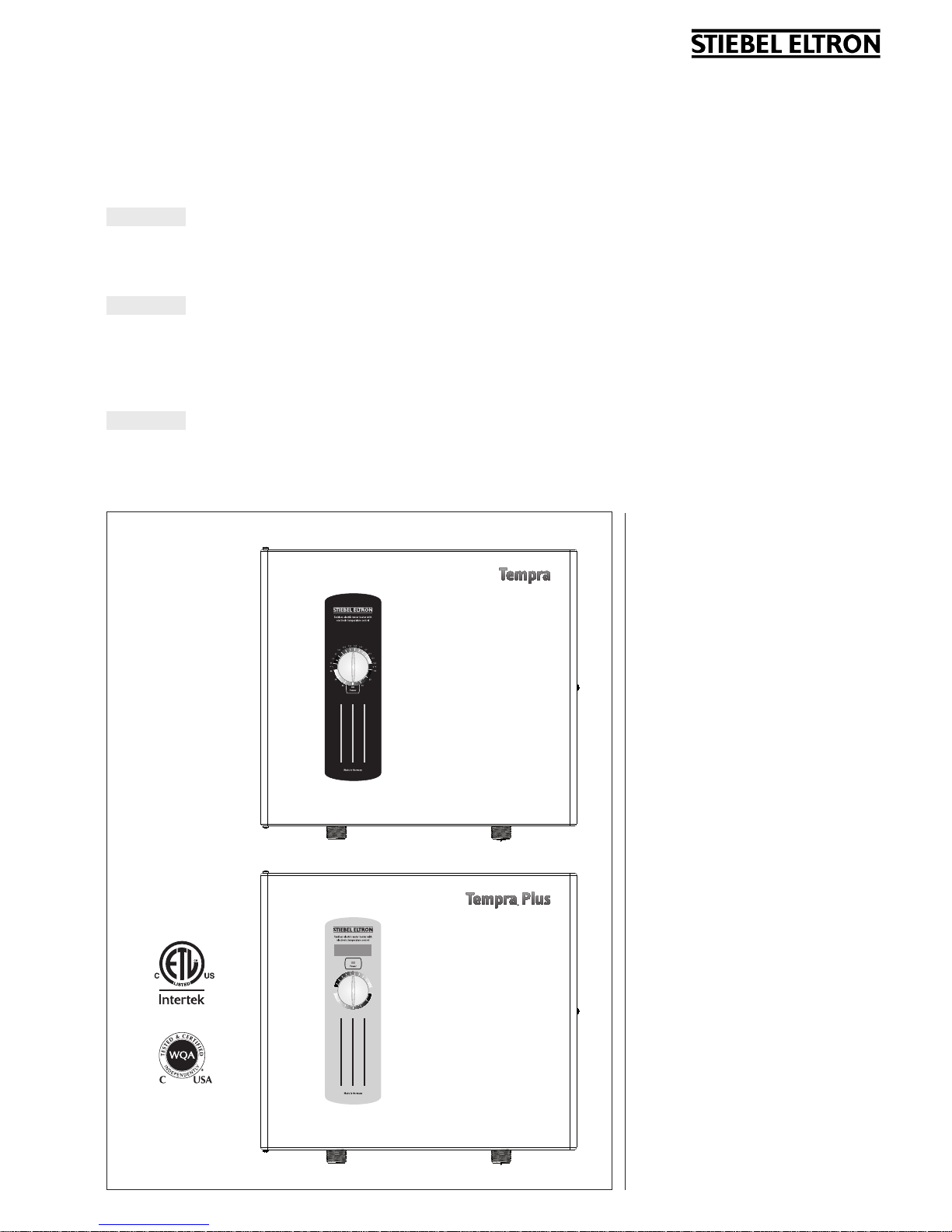
Tempra® 12 B, Tempra® 15 B, Tempra® 20 B, Tempra® 24 B
Tempra® 12 Plus, Tempra® 15 Plus, Tempra® 20 Plus,
Tempra® 24 Plus, Tempra® 29 Plus, Tempra® 36 Plus
English
TANKLESS ELECTRIC WATER HEATERS
INSTALLATION INSTRUCTIONS FOR THE LICENSED PLUMBER AND ELECTRICIAN
Español
CALENTADORES DE AGUA SIN TANQUE
INSTRUCCIONES PARA LA INSTALACIÓN POR UN PLOMERO Y ELECTRICISTA AUTORIZADO
Français
CHAUFFE-EAU INSTANTANéS éLECTRIQUES
INSTRUCTIONS DE MONTAGE POUR PLOMBIERS ET éLECTRICIENS AGRééSN
TEMPRA 12 - 24 B
TEMPRA 12 - 36 Plus
Français Sommaire
S1 Mesures de sécurité ____________________________________21
R1 Incrivez votre produit __________________________________21
1 Tableau indiquant montée en température
au-dessus de la température d’eau ambiante 22
2 Généralités ____________________________________________ 26
3 Montage de l‘appareil ______________________________ 26
4 Raccords d‘eau _______________________________________ 27
5 Raccordement électrique __________________________ 27
6 Premiers réglages ___________________________________ 27
7 Mise en ser vice du chauffe-eau __________________ 27
8 Entretien de routine _________________________________ 27
9 Caractéristiques techniques _______________________ 28
10 Dépannage____________________________________________ 28
11 Pièces de rechange _____________________________________ 29
12 Garantie ___________________________________________________ 31
English Table of contents
S1 Safety precautions _______________________________________ 2
R1 Register your product ___________________________________ 2
1 Table showing temperature increase above
ambient water temperature _________________________3
2 General ___________________________________________________7
3 Mounting the unit ______________________________________7
4 Water connections _____________________________________7
5 Electrical connection __________________________________8
6 Initial settings __________________________________________8
7 Putting the water heater into operation __________8
8 Normal maintenance __________________________________ 8
9 Technical Data __________________________________________9
10 Troubleshooting _______________________________________9
11 Spare parts ___________________________________________ 10
12 Warranty ______________________________________________ 31
Español Índice de materias
S1 Avisos de segurida ______________________________________ 12
R1 Para regis trar su nu evo equip o ______________________ 12
1 Aumento máximo de temperatura del
agua fría ent rante____________________________________ 13
2 Generalidades ________________________________________ 17
3 Montaje de la unidad _______________________________ 17
4 Conexiones de agua _________________________________ 18
5 Conexión eléctrica ___________________________________ 18
6 Ajustes iniciales ______________________________________ 18
7 Puesta en servicio del calentador de agua ____ 18
8 Mantenimiento normal _____________________________ 18
9 Datos técnicos_________________________________________ 19
10 Solución de problemas ____________________________ 19
11 Repuestos _____________________________________________ 20
12 Garantía ______________________________________________ 31
The Tempra® / Tempra®
Plus series is tested and
certified by WQA against
NSF/ANSI 372 for “lead
free“ compliance.
http://waterheatertimer.org/How-to-wire-Tankless-electric-water-heater.html
____________________________________________________________

– 2 –
General information
Read this entire manual. Failure to follow all
the guides, instructions and rules could cause
personal injury or property damage. Improper
installation, adjustment, alteration, service and
use of this unit can result in serious injury.
This unit must be installed by a licensed
electrician and plumber. The installation
must comply with all national, state and local
plumbing and electric codes. Proper installation
is the responsibility of the installer. Failure to
comply with the installation and operating
instructions or improper use voids the warranty.
Save these instructions for future reference.
Installer should leave these instructions with the
consumer.
If you have any questions regarding the
installation, use or operation of this water
heater, or if you need any additional installation
manuals, please call our technical service line at
800-582-8423 (USA and Canada only). If you are
calling from outside the USA or Canada, please
call USA 413-247-3380 and we will refer you to
a qualified Stiebel Eltron service representative
in your area.
!
THIS IS THE SAFETY ALERT SYMBOL. IT
IS USED TO ALERT YOU TO POTENTIAL
PERSONAL INJURY HAZARD. OBEY ALL SAFETY
MESSAGES THAT FOLLOW THIS SYMBOL TO
AVOID POSSIBLE INJURY OR DEATH.
S1 Safety precautions
!
PLEASE READ AND FOLLOW THESE
INSTRUCTIONS. FAILURE TO FOLLOW
THESE INSTRUCTIONS COULD RESULT IN
SERIOIUS BODILY INJURY OR DEATH.
THE UNIT MUST BE INSTALLED BY A
LICENSED ELECTRICIAN AND PLUMBER.
THE INSTALLATION MUST COMPLY WITH ALL
NATIONAL, STATE AND LOCAL PLUMBING AND
ELECTRIC CODES.
SERVICE OF THE UNIT MUST BE PERFORMED
BY QUALIFIED SERVICE TECHNICIANS.
BEFORE PROCEEDING WITH ANY INSTALLATION,
ADJUSTMENT, ALTERATION, OR SERVICE
OF THIS UNIT ALL CIRCUIT BREAKERS AND
DISCONNECT SWITCHES SERVICING THE UNIT
MUST BE TURNED OFF. FAILURE TO DO SO
COULD RESULT IN SERIOUS PERSONAL INJURY
OR DEATH.
NEVER REMOVE THE UNIT'S COVER UNLESS
THE ELECTRICITY SERVICING THE UNIT IS
TURNED OFF. FAILURE TO DO SO COULD RESULT
IN PERSONAL INJURY OR DEATH.
THE UNIT MUST BE PROPERLY GROUNDED.
FAILURE TO ELECTRICALLY GROUND THE
PRODUCT COULD RESULT IN SERIOUS
PERSONAL INJURY OR DEATH.
DANGER: WATER TEMPERATURES OVER
125°F CAN CAUSE SEVERE BURNS INSTANTLY
OR DEATH FROM SCALDING. A HOT WATER
SCALDING POTENTIAL EXISTS IF THE
THERMOSTAT ON THE UNIT IS SET TOO
HIGH. HOUSEHOLDS WITH SMALL CHILDREN,
DISABLED OR ELDERLY PERSONS MAY REQUIRE
THAT THE THERMOSTAT BE SET AT 120°F OR
LOWER TO PREVENT POSSIBLE INJURY FROM
HOT WATER.
R1 Register your product
YOU MUST REGISTER THIS PRODUCT
WITHIN 90 DAYS OF PURCHASE ON
OUR WEB SITE IN ORDER TO ACTIVATE THE
STANDARD WARRANTY OR TO BE ELIGIBLE FOR
THE EXTENDED WARRANTY. GO TO OUR WEB
SITE AT WWW.STIEBEL-ELTRON-USA.COM AND
CLICK ON REGISTER YOUR PRODUCT.
Before beginning the registration process,
we suggest that you gather the necessary
information which will be as follows:
Type, Example: TEMPRA 24 Plus (from the
white label that is on the right side of
the unit)
Number listed after "Nr."
Place of Purchase
Purchase Date
First & Last Name
Email address
Physical Address
Phone Number
IF YOU HAVE ANY QUESTIONS CONCERNING
THE REGISTRATION PROCESS OR WARRANTY
OPTIONS, PLEASE CONTACT STIEBEL ELTRON
USA DIRECTLY AT (800)-582-8423.
DO NOT TURN THE WATER HEATER TO
THE HIGHEST SETTING UNLESS A HIGH TEMP.
IS NEED FOR SANITARY PURPOSES, SUCH AS
FOR A COMMERCIAL KITCHEN.
IT IS SAFEST FOR THE USER TO KEEP THE
TEMPERATURE SETTING LOWER. WE RECOMMEND 110˚F TO 115˚F ( 43-46˚C ) FOR NORMAL HOUSEHOLD USE.
CHOOSING A LOW TEMPERATURE SETTING
ALSO INCREASES THE LIVE EXPECTANCY OF
THE TEMPRA UNIT DRAMATICALLY.
THE THREE YEAR WARRANTY COVERS ALL
PARTS BUT DOES NOT COVER DAMAGE TO
THE UNIT DUE TO HARD WATER (FOR THE
COMPLETE WARRANTY CHECK INSIDE THESE
INSTRUCTIONS). IF YOU KNOW OR SUSPECT
THAT THE WATER IN YOUR AREA IS HARD
(HAS A HIGH MINERAL CONTENT), IT IS NECESSARY TO INSTALL A WATER SOFTENING
DEVICE TO AVOID DAMAGE TO THE TEMRPA
UNIT.
– 3 –
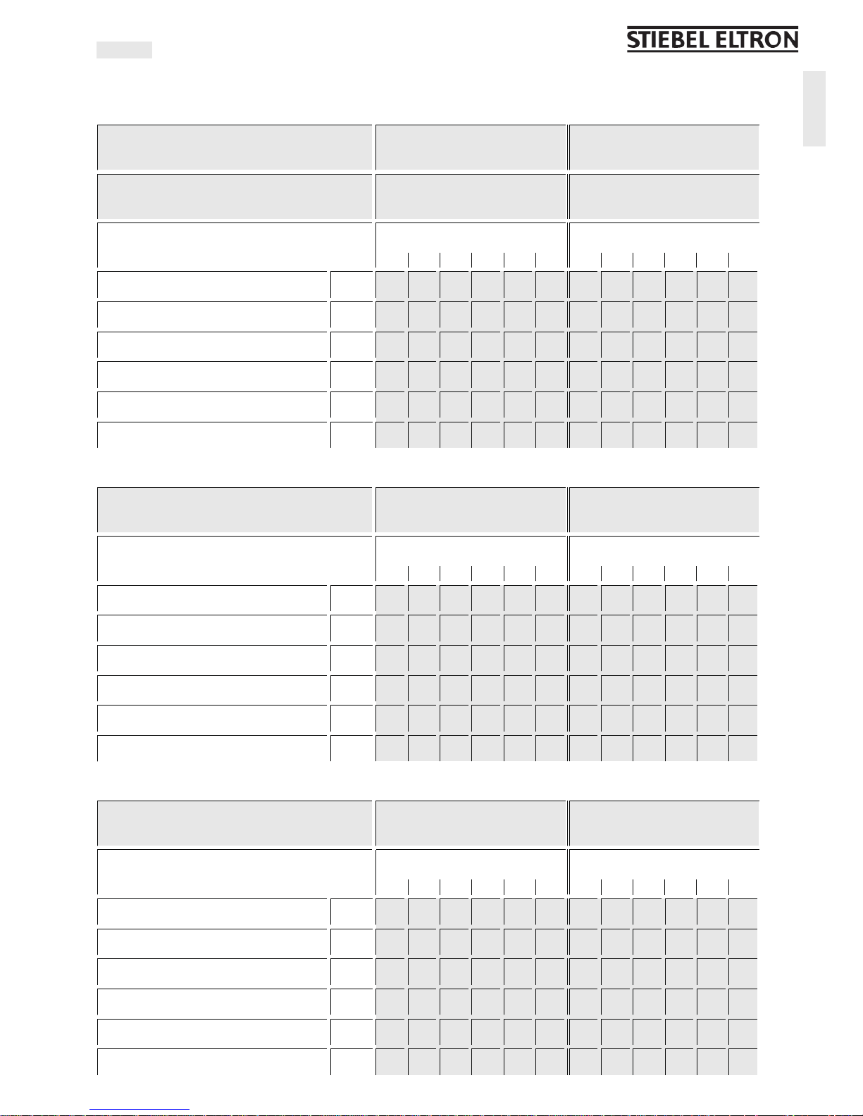
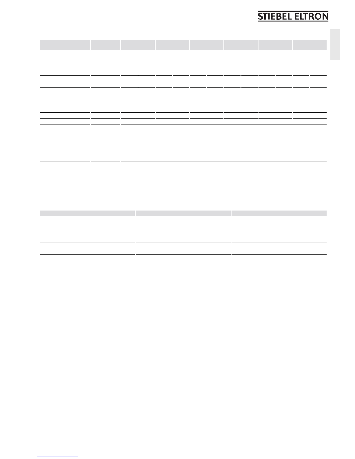
1 Table showing temperature increase above ambient water temperature
Maximum temperature increase above ambient water temperaturetLegend to figures
English
Warm water flow rate
GPM l/min
Warm water outlet temperature
140 °F 60 °C
TEMPRA 12 B / TEMPRA 12 Plus @ 208 V 9 kW 0.61 0.76 0.97 1.36 2.27 6.61 2.30 2.86 3.68 5.16 8.59 25.00
@ 220 - 240 V 12 kW 0.81 1.01 1.30 1.82 3.03 6.61 3.07 3.82 4.91 6.87 11.46 25.00
TEMPRA 15 B / TEMPRA 15 Plus @ 208 V 10,8 kW 0.73 0.91 1.17 1.63 2.72 6.61 2.76 3.44 4.42 6.19 10.31 25.00
@ 220 - 240 V 14.4 kW 0.97 1.21 1.56 2.18 3.63 6.61 3.68 4.58 5.89 8.25 13.75 25.00
TEMPRA 20 B / TEMPRA 20 Plus @ 208 V 14.4 kW 0.97 1.21 1.56 2.18 3.63 6.61 3.68 4.58 5.89 8.25 13.75 25.00
@ 220 - 240 V 19.2 kW 1.30 1.61 2.08 2.91 4.84 6.61 4.91 6.11 7.86 11.00 18.33 25.00
TEMPRA 24 B / TEMPRA 24 Plus @ 208 V 18 kW 1.22 1.51 1.95 2.72 4.54 6.61 4.60 5.73 7.36 10.31 17.18 25.00
@ 220 - 240 V 24 kW 1.62 2.02 2.59 3.63 6.05 6.61 6.14 7.64 9.82 13.75 22.91 25.00
TEMPRA 29 Plus @ 208 V 21.6 kW 1.46 1.82 2.33 3.27 5.45 6.61 5.52 6.87 8.84 12.37 20.62 25.00
@ 220 - 240 V 28.8 kW 1.95 2.42 3.11 4.36 6.61 6.61 7.36 9.16 11.78 16.50 25.00 25.00
TEMPRA 36 Plus @ 208 V 27 kW 1.82 2.27 2.92 4.09 6.61 6.61 6.90 8.59 11.05 15.47 25.00 25.00
@ 220 - 240 V 36 kW 2.43 3.03 3.89 5.45 6.61 6.61 9.21 11.46 14.73 20.62 25.00 25.00
Cold water inlet temperature °F °C
39 59 77 95 113 131 4 15 25 35 45 55
Warm water outlet temperature
113 °F 45 °C
TEMPRA 12 B / TEMPRA 12 Plus @ 208 V 9 kW 0,83 1,14 1,70 3,41 6,61 3,14 4,30 6,44 12,89 25,00
@ 220 - 240 V 12 kW 1,11 1,51 2,27 4,54 6,61 4,19 5,73 8,59 17,18 25,00
TEMPRA 15 B / TEMPRA 15 Plus @ 208 V 10,8 kW 1,00 1,36 2,04 4,09 6,61 3,77 5,16 7,73 15,47 25,00
@ 220 - 240 V 14.4 kW 1,33 1,82 2,72 5,45 6,61 5,03 6,87 10,31 20,62 25,00
TEMPRA 20 B / TEMPRA 20 Plus @ 208 V 14.4 kW 1,33 1,82 2,72 5,45 6,61 5,03 6,87 10,31 20,62 25,00
@ 220 - 240 V 19.2 kW 1,77 2,42 3,63 6,61 6,61 6,71 9,16 13,75 25,00 25,00
TEMPRA 24 B / TEMPRA 24 Plus @ 208 V 18 kW 1,66 2,27 3,41 6,61 6,61 6,29 8,59 12,89 25,00 25,00
@ 220 - 240 V 24 kW 2,21 3,03 4,54 6,61 6,61 8,38 11,46 17,18 25,00 25,00
TEMPRA 29 Plus @ 208 V 21.6 kW 1,99 2,72 4,09 6,61 6,61 7,54 10,31 15,47 25,00 25,00
@ 220 - 240 V 28.8 kW 2,66 3,63 5,45 6,61 6,61 10,06 13,75 20,62 25,00 25,00
TEMPRA 36 Plus @ 208 V 27 kW 2,49 3,41 5,11 6,61 6,61 9,43 12,89 19,33 25,00 25,00
@ 220 - 240 V 36 kW 3,32 4,54 6,61 6,61 6,61 12,57 17,18 25,00 25,00 25,00
Cold water inlet temperature °F °C
39 59 77 95 113 131 4 15 25 35 45 55
Warm water outlet temperature
105 °F 40 °C
TEMPRA 12 B / TEMPRA 12 Plus @ 208 V 9 kW 0,95 1,36 2,27 6,61 3,58 5,16 8,59 25,00
@ 220 - 240 V 12 kW 1,26 1,82 3,03 6,61 4,77 6,87 11,46 25,00
TEMPRA 15 B / TEMPRA 15 Plus @ 208 V 10,8 kW 1,14 1,63 2,72 6,61 4,30 6,19 10,31 25,00
@ 220 - 240 V 14.4 kW 1,51 2,18 3,63 6,61 5,73 8,25 13,75 25,00
TEMPRA 20 B / TEMPRA 20 Plus @ 208 V 14.4 kW 1,51 2,18 3,63 6,61 5,73 8,25 13,75 25,00
@ 220 - 240 V 19.2 kW 2,02 2,91 4,84 6,61 7,64 11,00 18,33 25,00
TEMPRA 24 B / TEMPRA 24 Plus @ 208 V 18 kW 1,89 2,72 4,54 6,61 7,16 10,31 17,18 25,00
@ 220 - 240 V 24 kW 2,52 3,63 6,05 6,61 9,55 13,75 22,91 25,00
TEMPRA 29 Plus @ 208 V 21.6 kW 2,27 3,27 5,45 6,61 8,59 12,37 20,62 25,00
@ 220 - 240 V 28.8 kW 3,03 4,36 6,61 6,61 11,46 16,50 25,00 25,00
TEMPRA 36 Plus @ 208 V 27 kW 2,84 4,09 6,61 6,61 10,74 15,47 25,00 25,00
@ 220 - 240 V 36 kW 3,78 5,45 6,61 6,61 14,32 20,62 25,00 25,00
Cold water inlet temperature °F °C
39 59 77 95 113 131 4 15 25 35 45 55
English
– 4 –
8 5/8 (220)2 9/16 (65)
16
5
/8 (420)4 (102)
14
1
/
2
(369)
11
/
16
(17,5)
4 5/8 (117)
TEMPRA 12 - 24 B
1
3
2
A
B
C26_02_02_0875
TEMPRA 12 - 36 Plus
4
TEMPRA 12 B/TEMPRA 12 Plus
TEMPRA 29, 36 Plus
5
8
12
9
13
TEMPRA 15, 20, 24 B
TEMPRA 15, 20, 24 Plus
7
3
1
2.1
11
C26_02_02_0874C26_02_02_0873 C26_02_02_0873
C26_02_02_0873
10
6

– 5 –
7 1/2 (190) 7 1/2 (190)
3
/
16
(5)
3
/4 (19,5)
12
1
/
2
(318)
3
/
8
(10)
1 (26)
D
1
2
G
14 15
16
17
14 15
16
17
E
C
1
2
C26_02_02_0877
26_02_02_0876
C26_02_02_0872
C26_02_02_0878
2
1
3
F
C26_02_02_0940
2
1
English
– 6 –
H
I
OFF
ON
OFF
ON
2
TEMPRA 12 B
TEMPRA 12 Plus
OFF
ON
OFF
ON
OFF
ON
OFF
ON
OFF
ON
OFF
ON
OFF
ON
OFF
ON
OFF
ON
OFF
ON
1
8794.02
8794.02
8794.02
C26_02_02_0881
C26_02_02_0881
C26_02_02_0881
TEMPRA 15, 20, 24 B
TEMPRA 15, 20, 24 Plus
TEMPRA 29, 36 Plus
TEMPRA 36 Plus TEMPRA 29 Plus
TEMPRA 24 B
TEMPRA 24 Plus
TEMPRA 15/20 B
TEMPRA 15/20 Plus
TEMPRA 12 B
TEMPRA 12 Plus
CKT 1
CKT 2
CKT 3
CKT 1
CKT 2
CKT 3
CKT 1
CKT 2
CKT 1
CKT 1
CKT 2
642
531
642
531
642
531
4251425142
51
642
531
642
531
642
531
6
4
2
5
3
1
425142
51
6
4
2
5
3
1
6
4
2
5
3
1
4
2
5
1
4
2
5
1
6
11/1 2
5
4
9/10
3
2
7/8
1
13
6
11/1 2
5
4
9/10
3
2
7/8
1
13
6
11/1 2
5
4
9/10
3
2
7/8
1
13
6
11/1 2
5
4
9/10
3
2
7/8
1
13
6
11/1 2
5
4
9/10
3
2
7/8
1
13
26_02_02_0889
CKT 1
CKT 2
CKT 3 CKT 1 CKT 2 CKT 1
– 7 –
English
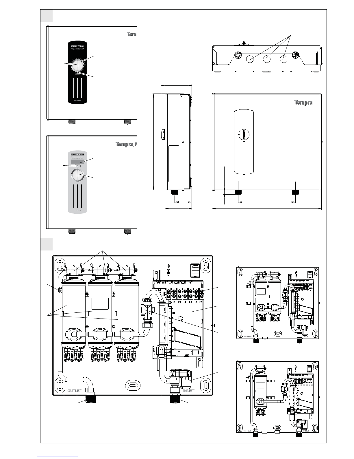
1 Temperature adjustment knob
2 Temperature scale
2.1 Temperature display
3 "Power" light
4 Knock-outs for wires
5 Safety thermal cut out
6 Outlet temperature sensor
7 Wiring block
8 Electronic control unit
9 Heating system
10 Flow sensor
11 Motor-operated valve
12 Cold water connection
13 Hot water connection
14 Hot valve (left)
15 Cold valve (right)
16 Sink
17 Water supply line for faucet/tap
installation
2 General
!
DANGER: WATER TEMPERATURES OVER
125 °F CAN CAUSE SEVERE BURNS
INSTANTLY OR DEATH FROM SCALDING. A
HOT WATER SCALDING POTENTIAL EXISTS IF
THE THERMOSTAT ON THE UNIT IS SET TOO
HIGH. HOUSEHOLDS WITH SMALL CHILDREN,
DISABLED OR ELDERLY PERSONS MAY REQUIRE
THAT THE THERMOSTAT BE SET AT 120 °F OR
LOWER TO PREVENT POSSIBLE INJURY FROM
HOT WATER.
The TEMPRA and TEMPRA Plus units are
designed to supply hot water for a house,
apartment or certain commercial applications.
Unlike a conventional storage type water
heater the TEMPRA tankless water heater does
not store hot water. Instead, water is heated
instantaneously as it flows through the unit.
The TEMPRA offers greater energy efficiency
than storage type water heaters due to the
absence of stand-by losses and reduced hot
water pipe runs.
The input of heat into the water is controlled
electronically. The TEMPRA will deliver any
water temperature between 86 °F (30 °C)
THIS MANUAL MUST BE READ CAREFULLY BEFORE ATTEMPTING TO INSTALL THE TEMPRA WATER HEATER.
IF YOU DO NOT FOLLOW THE SAFETY RULES OR THE INSTRUCTIONS OUTLINED IN THIS MANUAL, THE UNIT
MAY NOT OPERATE PROPERLY AND IT COULD CAUSE PROPERTY DAMAGE, SERIOUS BODILY INJURY AND/
OR DEATH.
STIEBEL ELTRON, INC. WILL NOT BE LIABLE FOR ANY DAMAGES BECAUSE OF FAILURE TO COMPLY WITH THE
INSTALLATION AND OPERATING INSTRUCTIONS OUTLINED IN THIS MANUAL OR BECAUSE OF IMPROPER USE.
IMPROPER USE INCLUDES THE USE OF THIS APPLIANCE TO HEAT ANY LIQUID OTHER THAN WATER. FAILURE
TO COMPLY WITH THE INSTALLATION AND OPERATING INSTRUCTIONS OR IMPROPER USE VOIDS WARRANTY.
NEVER REMOVE THE UNIT’S COVER UNLESS THE ELECTRICITY IS TURNED OFF.
IF YOU HAVE ANY QUESTIONS REGARDING THE INSTALLATION OR OPERATION OF THIS WATER HEATER, OR
IF YOU NEED ANY ADDITIONAL INSTALLATION MANUALS, PLEASE CALL OUR TECHNICAL SERVICE LINE ON
800-582-8423 (USA AND CANADA ONLY). IF YOU ARE CALLING FROM OUTSIDE THE U.S. OR CANADA, PLEASE
CALL USA 413-247-3380 AND WE WILL REFER YOU TO A QUALIFIED STIEBEL ELTRON SERVICE REPRESENTATIVE
IN YOUR AREA.
and 140 °F (60 °C). Please set the desired
temperature using the knob on the front cover.
The TEMPRA PLUS Temperature adjustment
knob can be set to: OFF, 86...140 °F (30...60 °C).
The TEMPRA has a °F and a °C scale. The output
temperature of the TEMPRA Plus is shown
in the digital display in °F or °C units. (°F or
°C units can be selected during installation,
factory setting: °F). The maximum temperature
is electronically limited to 140 °F (60 °C).
Recommended is a setting of
108 °F (42 °C) to 116 °F (47 °C).
The outlet temperature of the TEMPRA Plus
can be limited to 109 °F (43 °C).
Tempra B units:
In case the "Power” LED is flashing while the
unit operates, the water flow rate exceeds the
heating capacity of the unit. Reduce the hot
water flow rate in order to let the unit achieve
the set point temperature.
Tempra Plus units:
Tempra Plus units have Advanced Flow
Control. This technology is designed to reduce
water flow to maintain consistent temperature
if the unit's heating capacity is exceeded. It
does this by using a computer controlled,
motorized valve to temporarily reduce water
flow until the demand is reduced. This is
normal operation and does not necessarily
mean the unit is clogged or obstructed.
In case you have questions regarding the way
you plan to use the TEMPRA unit, please call
our technical service line at 800-582-8423 (USA
and Canada). For service outside the U.S. and
Canada, please call us at USA 413-247-3380.
You can also e-mail us at info@stiebel-eltronusa.com or fax us at USA 413-247-3369.
The TEMPRA can be used for the following
applications.
G
1
Typical residential installation
G
2
Typical commercial installation
3 Mounting the unit
!
NOTICE: UNIT MUST BE INSTALLED
IN A VERTICAL POSITION WITH THE
WATER FITTINGS POINTING DOWNWARD.
WARNING: DO NOT INSTALL UNIT WHERE
IT WOULD ROUTINELY BE SPLASHED WITH
WATER. ELECTRIC SHOCK MAY RESULT.
CAUTION: HOT WATER OUTLET PIPES LEAVING
UNIT CAN BE HOT TO THE TOUCH. INSULATION
MUST BE USED FOR HOT WATER PIPES BELOW
36" DUE TO BURN RISK TO CHILDREN.
!
NOTICE: THIS UNIT SHOULD NOT
BE INSTALLED IN A LOCATION
WHERE IT MAY BE EXPOSED TO FREEZING
TEMPERATURES (LESS THAN 36 °F). IF
THE UNIT MAY BE SUBJECT TO FREEZING
TEMPERATURES ALL WATER MUST BE DRAINED
FROM THE UNIT. FAILURE TO COMPLY WITH
THIS INSTRUCTION VOIDS ALL WARRANTIES.
THE UNIT SHOULD BE LOCATED IN AN AREA
WHERE WATER LEAKAGE FROM THE UNIT OR
CONNECTIONS WILL NOT RESULT IN DAMAGE
TO THE AREA ADJACENT TO THE UNIT. IF
SUCH A LOCATION CANNOT BE AVOIDED IT
IT RECOMMENDED THAT A DRAIN PAN BE
INSTALLED UNDER THE UNIT.
1. Install TEMPRA as close as possible to the
main hot water draw-off points.
2. Install TEMPRA in a frost free area. If frost
might occur, remove unit before freezing
temperatures set in.
3. Leave a minimum of 5" of clearance on all
sides for servicing.
4. Remove the cover screw with chopper disc
and open the cover
C
.
5. Mount unit securely to wall by putting at
least three screws through mounting holes
E
1 -
3.
Screws and plastic wall anchors for
mounting on masonry or wood are
provided.
– 8 –
4 Water connections
!
NOTICE: EXCESSIVE HEAT FROM
SOLDERING ON COPPER PIPES NEAR
THE TEMPRA MAY CAUSE DAMAGE.
THE COLD WATER CONNECTION TO THE UNIT
MUST BE DISCONNECTED PERIODICALLY IN
ORDER TO CLEAN THE FILTER SCREEN. IT
IS REQUIRED TO USE WATER CONNECTIONS
THAT ARE EASILY DETACHABLE SUCH AS
BRAIDED STEEL FLEX CONNECTORS.
!
NOTICE: HARD WATER OR WATER
WITH A HIGH MINERAL COUNT MAY
DAMAGE THE UNIT. DAMAGE TO THE UNIT
CAUSED BY SCALE OR A HIGH MINERAL
COUNT IS NOT COVERED UNDER THE
WARRANTY.
1. All plumbing work must comply with
national and applicable state and local
plumbing codes.
2. A pressure reducing valve must be installed
if the cold water supply pressure exceeds
150 PSI (10 bar).
3. Make certain that the cold water supply line
has been flushed to remove any scale and
dirt.
4.
D Also, the TEMPRA unit has a built in filter
screen
1
that should be cleaned from time
to time. Clean screen and put the screen
and the washer
2
back into their original
position.
5. The cold water connection (inlet) is on the
right side of the unit, and the hot water
connection (outlet) is on the left side of
the unit.
6. The cold water connection to the unit must
be disconnected periodically in order to
access and clean the filter screen. It is
required to use water connections that are
easily detachable such as braided steel flex
connectors.
!
7. Tankless water heaters such as the
TEMPRA are not required to be equipped
with a Pressure and Temperature Relief Valve
(P&T). If the local inspector will not pass the
installation without a P&T, it should be installed on the hot water outlet side of
the unit.
8. The TEMPRA on the hot side is designed for
connection to copper tubing, PEX tubing or
a braided stainless steel hose with a 3/4"
NPT female tapered thread.
The plumbing on the cold water inlet
side needs to be such that it can easily be
removed to allow access to the inlet filter
screen. The easiest way to achieve this is to
us a stainless steel braided hose connector.
If soldering near the unit is necessary,
please direct the flame away from the
housing of the unit in order to avoid
damage.
9. When all plumbing work is completed,
check for leaks and take corrective action
before proceeding.
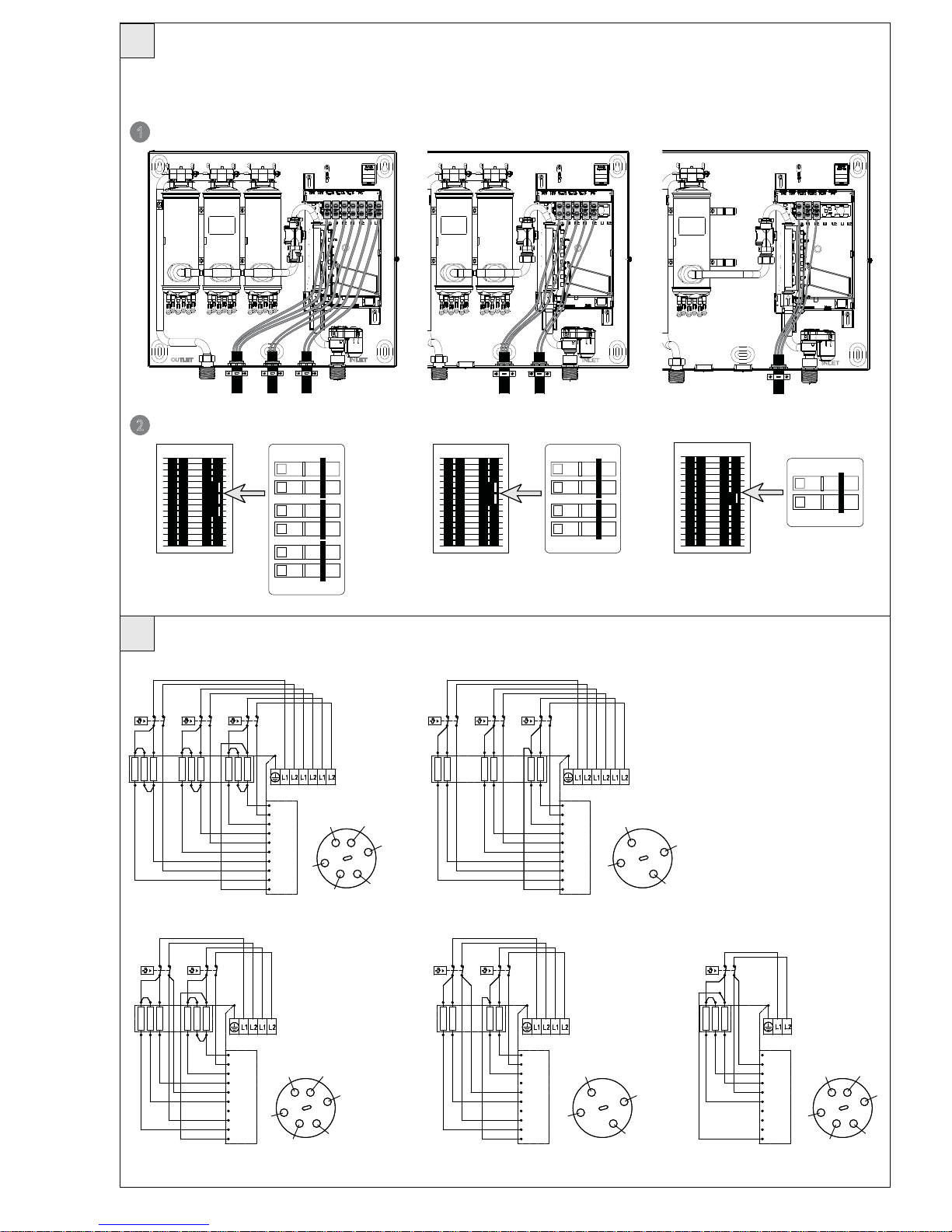
5 Electrical connection
!
WARNING: BEFORE BEGINNING ANY
WORK ON THE ELECTRIC INSTALLATION,
BE SURE THAT MAIN BREAKER PANEL SWITCHES
ARE "OFF" TO AVOID ANY DANGER OF ELECTRIC
SHOCK. ALL MOUNTING AND PLUMBING MUST
BE COMPLETED BEFORE PROCEEDING WITH
ELECTRICAL HOOK-UP. WHERE REQUIRED BY
LOCAL, STATE OR NATIONAL ELECTRICAL CODES
THE CIRCUITS SHOULD BE EQUIPPED WITH A
"GROUND FAULT INTERRUPTER".
THE UNIT MUST BE PROPERLY GROUNDED
IN ACCORDANCE WITH STATE AND LOCAL
CODES, OR IN ABSENCE OF SUCH CODES, IN
ACCORDANCE WITH NATIONAL ELECTRIC CODE
OR THE CANADIAN ELECTRIC CODE. FAILURE TO
ELECTRICALLY GROUND THE PRODUCT COULD
RESULT IN SERIOUS PERSONAL INJURY OR DEATH.
1. All electrical work must comply with national
and applicable state and local electrical codes.
2.
H The TEMPRA should be connected to
properly grounded dedicated branch circuits
of proper voltage rating. Ground must
be brought to the "Ground" at the circuit
breaker panel.
TEMPRA 12 B/Plus: These units can be
connected to a single circuit. Use a supply
cable protected by a double pole breaker (see
2
).
The TEMPRAS 15 to 36 must have multiple
power sources.
TEMPRA 15, 20 or 24 B/Plus: These units
require two independant circuits. Use two
supply cables protected by two separate
double pole breakers (see
2
).
TEMPRA 29 or 36 Plus These units require
three independant circuits. Use three supply
cables protected by three separate double
pole breakers (see
2
).
Please refer to the technical data table for
the correct wire and circuit breaker size. In
all cases, make sure that the unit is properly
grounded.
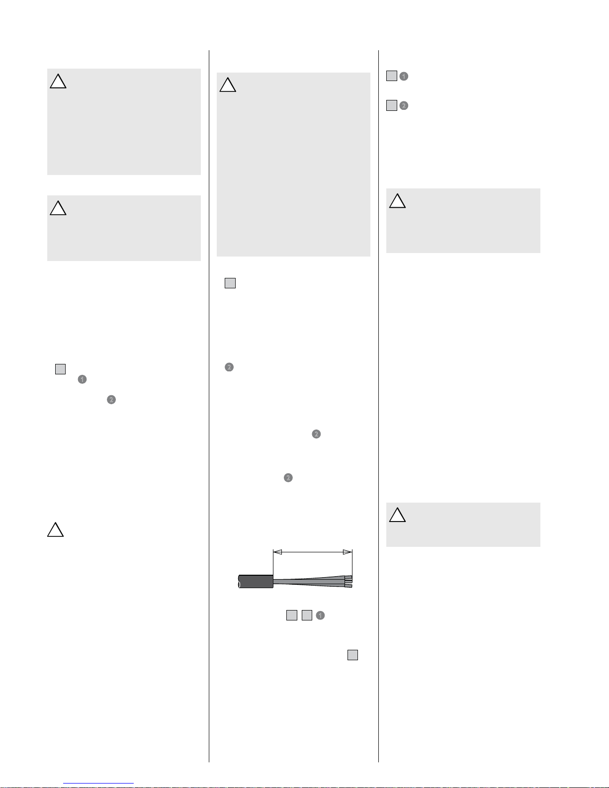
3. Cut the electrical connection cable to length
and strip.
15
(380)
26_02_02_0893
4. The wire must be fed through the knockouts located between the hot and cold
water connections
A , H
1
. The "live"
wires must be connected to the slots on
the terminal block marked L1 and L2. The
ground wire must be connected to slot
marked with the ground symbol (see
I ).
6 Initial settings
F
1
Selection of °F or °C units
– Set jumper on the dial-printed circuit board
to °F or °C.
F
2
Temperature limiter
The TEMPRA PLUS output temperature can be
limited to 109 °F (43 °C) by setting the jumper to
position T
red
(reduced temperature)
7 Putting the water
heater into operation
!
WARNING: OPEN HOT WATER FAUCET
FOR A FEW MINUTES UNTIL WATER
FLOW IS CONTINUOUS AND ALL AIR IS PURGED
FROM WATER PIPES. THE UNIT’S COVER MUST
BE INSTALLED BEFORE THE CIRCUIT BREAKERS
ARE TURNED ON.
1. Close the cover and fix it using the screw
with chopper disc.
2. Turn on circuit breakers to bring electrical
power to the unit.
3. Turn the temperature selector clockwise and
anti-clockwise, to calibrate the set value
transducer.
4. Adjust the water temperature to the desired
level using the knob on the front cover of
the unit.
5. Turn on hot water and wait twenty seconds
until temperature has stabilized.
6. Check the water temperature with your
hand and make sure that it does not feel
too hot. Reduce if necessary.
7. Explain to the user how the unit works and
familiarise him or her with its use.
Advise the user about possible hazards (hot
water temperature up to 140 °F / 60 °C).
Hand over these instructions, to be kept for
future reference.
8 Normal maintenance
!
NOTICE: THE TEMPRAS DO NOT CONTAIN
ANY PARTS SERVICEABLE BY THE LAY
PERSON. IN CASE OF MALFUNCTION PLEASE
CONTACT A LICENSED PLUMBER OR ELECTRICIAN.
STIEBEL ELTRON TEMPRA tankless water heaters
are designed for a very long service life. Actual
life expectancy will vary with water quality and
use. The unit itself does not require any regular
maintenance. However, to ensure consistent
water flow, it is recommended to periodically
remove scale and dirt that may build up at the
aerator of the faucet(s), the filter screen in the
unit, or in the shower head.
– 9 –
English
9 Technical Data
Model
7(035$b% 7(035$b% 7(035$b% 7(035 $b%
7(035$bb3OXV 7(035 $bb3OXV 7(035$bb3OXV 7(035$bb3OXV 7(035$bb3OXV 7(035$bb3OXV
Phase 1 1 1 1 1 1
Voltage V 208 240 208 240 208 240 208 240 208 240 208 240
Wattage kW 9 12 10.8 14.4 14.4 19.2 18 24 21.6 28.8 27 36
Max. amp, load A 44 50 2 x 26 2 x 30 2 x 35 2 x 40 2 x 44 2 x 50 3 x 35 3 x 40 3 x 44 3 x 50
Min. required circuit breaker size
A 60 60 2 x 40 2 x 40 2 x 50 2 x 50 2 x 60 2 x 60 3 x 50 3 x 50 3 x 60 3 x 60
Required wire size AWG COPPER 6 6 2 x 8 2 x 8 2 x 8 2 x 8 2 x 6 2 x 6 3 x 8 3 x 8 3 x 6 3 x 6
Inlet temperature, max. °F (°C) 131 (55)
Water flow to activate unit tGPM (tl/min) 0.37 (1.4) 0.58 (2.2) 0.58 (2.2) 0.58 (2.2) 0.87 (3.3) 0.87 (3.3)
Nominal water volume GAL (l) 0.13 (0.5) 0.26 (1.0) 0.26 (1.0) 0.26 (1.0) 0.39 (1.5) 0.39 (1.5)
Working pressure, max. PSI (bar) 145 (10)
Tested to pressure PSI (bar) 290 (20)
Weight lbs. (kg) 13.2 (6.1) 15.4 (7.3) 15.4 (7.3) 15.4 (7.3) 17.6 (8.6) 17.6 (8.6)
Dimensions
height
depth
width
inch (mm)
14 1/2 (369)
4 5/8 (117)
16 5/8 (420)
Water connections NPT 3/4"
– Tankless water heaters are considered a non-continuous load
– Conductors should be sized to maintain a voltage drop of less than 3 % under load
10 Troubleshooting
Symptom 3RVVLEOHFDXVH 6ROXWLRQ
No hot water
– circuit breakers off
– safety thermal cut-out tripped
– not enough flow rate to activate unit
– turn circuit breakers on
– reset safety thermal cut-out
– clean filter screen at unit
– clean faucet aerator or shower head
Not enough hot water – filter screen clogged – clean filter screen at unit
Water not hot enough
– water flow rate too high
– voltage too low
– reduce water flow rate until power light on front
cover stops blinking
– supply correct voltage to unit
If you are not able to resolve a problem please contact us toll free at 800-582-8423 before removing the unit from the wall.
STIEBEL ELTRON is happy to provide technical assistance. In most instances, we can resolve the problem over the phone.
– 10 –
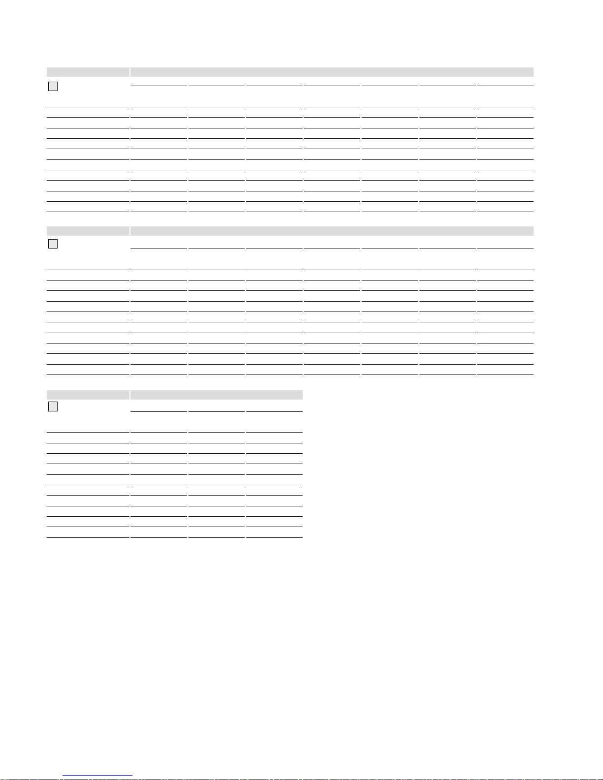
11 Spare parts
Model 6SDUHSDU W1R
J
1 2 3 4 5 6 7
Housing
Temp. control
knob
Wiring block Heating system Safety thermal
cut out
Electronic control
device
Flow sensor
TEMPRA 12 B 286356 254307 279998 286360 286369 286366 286461
TEMPRA 15 B 286356 254307 279997 286361 286369 286844 286461
TEMPRA 20 B 286356 254307 279997 286362 286369 286844 286461
TEMPRA 24 B 286356 254307 279997 286364 286369 286367 286461
TEMPRA 12 Plus 286370 254307 279998 286360 286369 286375 286461
TEMPRA 15 Plus 286370 254307 279997 286361 286369 286845 286461
TEMPRA 20 Plus 286370 254307 279997 286362 286369 286845 286461
TEMPRA 24 Plus 286370 254307 279997 286364 286369 286376 286461
TEMPRA 29 Plus 286370 254307 279996 286373 286369 286378 286461
TEMPRA 36 Plus 286370 254307 279996 286374 286369 286379 286461
Model 6SDUHSDU W1R
J
8 9 10 11 12 13 14
Plumbing
connection 3/4"
Advanced Flow
Control
Electronic temp.
control
Jumpers Temperature
sensor
Filter screen Set point case
TEMPRA 12 B 278698 --- 286359 283455 280677 056755 280730
TEMPRA 15 B 278698 --- 286359 283455 280677 056755 280730
TEMPRA 20 B 278698 --- 286359 283455 280677 056755 280730
TEMPRA 24 B 278698 --- 286359 283455 280677 056755 280730
TEMPRA 12 Plus 278698 220502 286372 283455 280677 056755 280730
TEMPRA 15 Plus 278698 220502 286372 283455 280677 056755 280730
TEMPRA 20 Plus 278698 220502 286372 283455 280677 056755 280730
TEMPRA 24 Plus 278698 220502 286372 283455 280677 056755 280730
TEMPRA 29 Plus 278698 220502 286372 283455 280677 056755 280730
TEMPRA 36 Plus 278698 220502 286372 283455 280677 056755 280730
Model 6SDUHSDU W1R
J
15 16 17
Inlet pipe elbow Valve assembly Axis connection
plug
TEMPRA 12 B 278695 --- 254312
TEMPRA 15 B 278695 --- 254312
TEMPRA 20 B 278695 --- 254312
TEMPRA 24 B 278695 --- 254312
TEMPRA 12 Plus --- 280622 254312
TEMPRA 15 Plus --- 280622 254312
TEMPRA 20 Plus --- 280622 254312
TEMPRA 24 Plus --- 280622 254312
TEMPRA 29 Plus --- 280622 254312
TEMPRA 36 Plus --- 280622 254312
 Loading...