

Page 1
OPERATION AND INSTALLATION
OPERACIÓN E INSTALACIÓN
UTILISATION ET INSTALLATION
TANKLESS ELECTRIC WATER HEATERS | CALENTADORES DE AGUA SIN TANQUE | CHAUFFE-EAU
INSTANTANÉS ÉLECTRIQUES
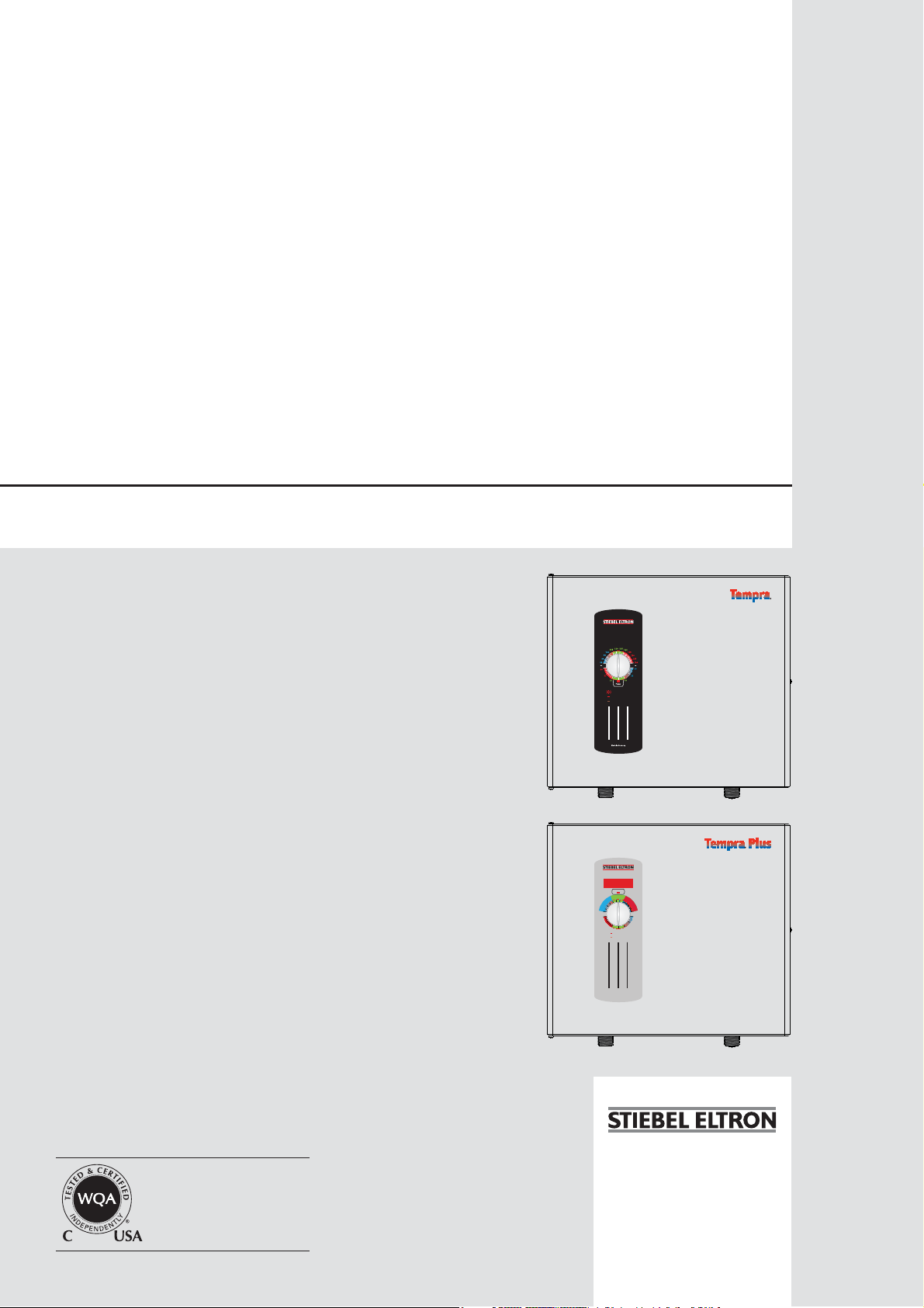
» TEMPRA® 12 B
» TEMPRA® 15 B
Tankless Electric Water Heater
» TEMPRA® 20 B
» TEMPRA® 24 B
» TEMPRA® 29 B
» TEMPRA® 36 B
» TEMPRA® 12 PLUS
»TEMPRA® 15 PLUS
»TEMPRA® 20 PLUS
» TEMPRA® 24 PLUS
» TEMPRA® 29 PLUS
» TEMPRA® 36 PLUS
with electronic temperature control
|
g
n
i
h
s
a
W
d
n
a
H
°F °C
e
d
i
s
e
R
Blinking: maximum power,
less than set point temp.
Steady: unit operating
Off: unit off
i
a
t
n
l
U
s
e
|
C
o
m
S
m
C
A
e
L
D
r
I
c
N
i
G
a
D
l
A
O
N
G
n
E
l
R
y
The TEMPRA series is
tested and certified by WQA
against NSF/ANSI 372 for
“lead free“ compliance.
Tankless Electric Water Heater
with electronic temperature control
Power
t
n
e
d
i
s
e
R
g
n
i
h
s
a
W
d
n
a
H
On: unit operating
Off: unit off
Made in Germany
i
a
l
U
s
e
C
o
m
m
S
C
A
e
L
r
D
c
I
N
i
G
a
D
l
A
O
N
n
G
E
l
y
R
Page 2
ENGLISH TABLE OF CONTENTS
1. General Information _____________________________________________2
S1 Safety Precautions _______________________________________________2
2. Table showing temperature increase above ambient water
temperature_______________________________________________________3
3. General ____________________________________________________________7
4. Mounting the unit ________________________________________________7
5. Water connections _______________________________________________8
6. Electrical connection _____________________________________________8
7. Initial settings ____________________________________________________9
8. Putting the water heater into operation _______________________9
9. Normal maintenance _____________________________________________9
10. Technical Data ____________________________________________________9
11. Troubleshooting ________________________________________________ 10
12. Spare parts _____________________________________________________ 10
13. Warranty ________________________________________________________ 11
1. General Information
Read this entire manual. Failure to follow all the guides,
instructions and rules could cause personal injury or property
damage. Improper installation, adjustment, alteration, service
and use of this unit can result in serious injury.
This unit must be installed by a licensed electrician and
plumber. The installation must comply with all national, state
and local plumbing and electric codes. Proper installation is
the responsibility of the installer. Failure to comply with the
installation and operating instructions or improper use voids the
warranty.
Save these instructions for future reference. Installer should leave
these instructions with the consumer.
If you have any questions regarding the installation, use or
operation of this water heater, or if you need any additional
installation manuals, please call our technical service line at 800582-8423 (USA and Canada only). If you are calling from outside
the USA or Canada, please call USA 413-247-3380 and we will
refer you to a qualified Stiebel Eltron service representative in
your area.
THIS IS THE SA FET Y ALERT SYMBOL. IT IS USED TO ALERT
!
YOU TO POTENTIAL PERSONAL INJURY HAZARD. OBEY
ALL SAFETY MESSAGES THAT FOLLOW THIS SYMBOL TO
AVOID POSSIBLE INJURY OR DEATH.
S1 Safety Precautions
PLEASE READ AND FOLLOW THESE INSTRUCTIONS.
!
FAILURE TO FOLLOW THESE INSTRUCTIONS COULD
RESULT IN SERIOIUS BODILY INJURY OR DEATH.
THE UNIT MUST BE INSTALLED BY A LICENSED ELECTRICIAN
AND PLUMBER. THE INSTALLATION MUST COMPLY
WITH ALL NATIONAL, STATE AND LOCAL PLUMBING AND
ELECTRIC CODES.
SERVICE OF THE UNIT MUST BE PERFORMED BY QUALIFIED
SERVICE TECHNICIANS.
BEFORE PROCEEDING WITH ANY INSTALLATION,
ADJUSTMENT, ALTERATION, OR SERVICE OF THIS UNIT
ALL CIRCUIT BREAKERS AND DISCONNECT SWITCHES
SERVICING THE UNIT MUST BE TURNED OFF. FAILURE
TO DO SO COULD RESULT IN SERIOUS PERSONAL INJURY
OR DEATH.
NEVER REMOVE THE UNIT'S COVER UNLESS THE
ELECTRICITY SERVICING THE UNIT IS TURNED OFF.
FAILURE TO DO SO COULD RESULT IN PERSONAL INJURY
OR DEATH.
THE UNIT MUST BE PROPERLY GROUNDED. FAILURE TO
ELECTRICALLY GROUND THE PRODUCT COULD RESULT IN
SERIOUS PERSONAL INJURY OR DEATH.
– 2 –
DANGER: WATER TEMPERATURES OVER 125°F CAN
CAUSE SEVERE BURNS INSTANTLY OR DEATH FROM
SCALDING. A HOT WATER SCALDING POTENTIAL EXISTS
IF THE THERMOSTAT ON THE UNIT IS SET TOO HIGH.
HOUSEHOLDS WITH SMALL CHILDREN, DISABLED OR
ELDERLY PERSONS MAY REQUIRE THAT THE THERMOSTAT
BE SET AT 120°F OR LOWER TO PREVENT POSSIBLE INJURY
FROM HOT WATER.
Page 3
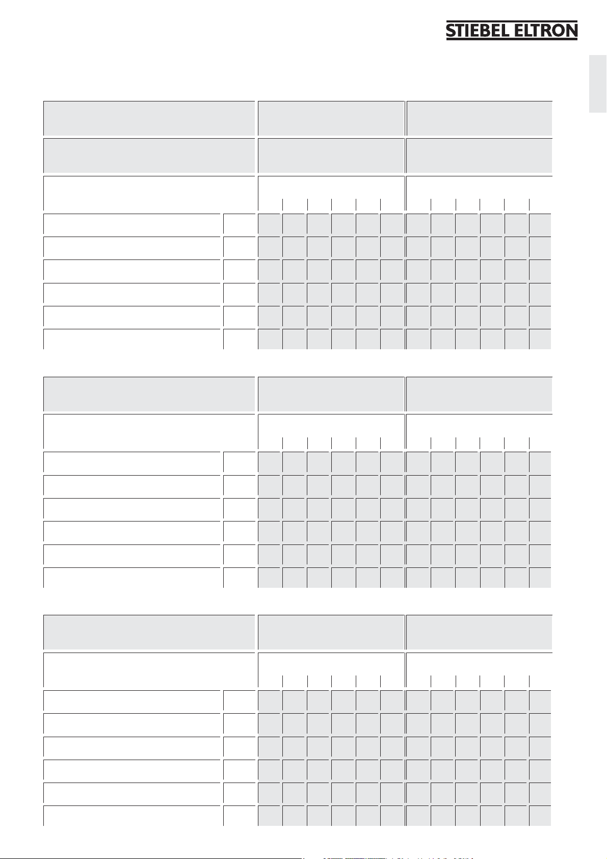
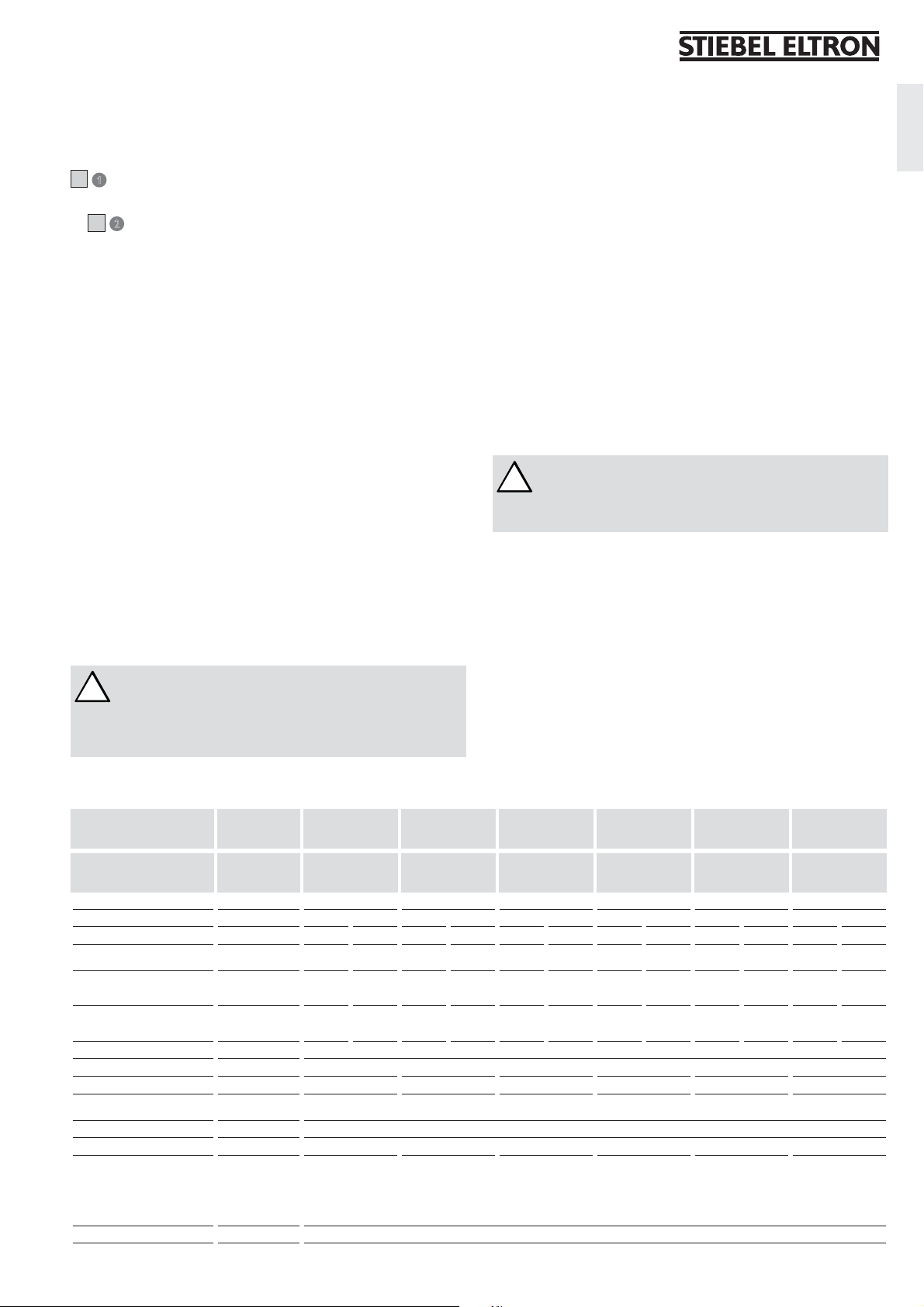
2. Table showing temperature increase above ambient water temperature
Maximum temperature increase above ambient water temperaturetLegend to figures
Warm water flow rate
GPM l/min
Warm water outlet temperature
105 °F 40 °C
Cold water inlet temperature °F °C
39 59 77 95 113 131 4 15 25 35 45 55
TEMPRA 12 B / TEMPRA 12 Plus @ 208 V 9 kW 0,95 1,36 2,27 6,61 3,58 5,16 8,59 25,00
@ 220 - 240 V 12 kW 1,26 1,82 3,03 6,61 4,77 6,87 11,46 25,00
TEMPRA 15 B / TEMPRA 15 Plus @ 208 V 10,8 kW 1,14 1,63 2,72 6,61 4,30 6,19 10,31 25,00
@ 220 - 240 V 14.4 kW 1,51 2,18 3,63 6,61 5,73 8,25 13,75 25,00
TEMPRA 20 B / TEMPRA 20 Plus @ 208 V 14.4 kW 1,51 2,18 3,63 6,61 5,73 8,25 13,75 25,00
@ 220 - 240 V 19.2 kW 2,02 2,91 4,84 6,61 7,64 11,00 18,33 25,00
TEMPRA 24 B / TEMPRA 24 Plus @ 208 V 18 kW 1,89 2,72 4,54 6,61 7,16 10,31 17,18 25,00
@ 220 - 240 V 24 kW 2,52 3,63 6,05 6,61 9,55 13,75 22,91 25,00
TEMPRA 29 B / TEMPRA 29 Plus @ 208 V 21.6 kW 2,27 3,27 5,45 6,61 8,59 12,37 20,62 25,00
@ 220 - 240 V 28.8 kW 3,03 4,36 6,61 6,61 11,46 16,50 25,00 25,00
TEMPRA 36 B / TEMPRA 36 Plus @ 208 V 27 kW 2,84 4,09 6,61 6,61 10,74 15,47 25,00 25,00
@ 220 - 240 V 36 kW 3,78 5,45 6,61 6,61 14,32 20,62 25,00 25,00
English
Warm water outlet temperature
Cold water inlet temperature °F °C
39 59 77 95 113 131 4 15 25 35 45 55
TEMPRA 12 B / TEMPRA 12 Plus @ 208 V 9 kW 0,83 1,14 1,70 3,41 6,61 3,14 4,30 6,44 12,89 25,00
@ 220 - 240 V 12 kW 1,11 1,51 2,27 4,54 6,61 4,19 5,73 8,59 17,18 25,00
TEMPRA 15 B / TEMPRA 15 Plus @ 208 V 10,8 kW 1,00 1,36 2,04 4,09 6,61 3,77 5,16 7,73 15,47 25,00
@ 220 - 240 V 14.4 kW 1,33 1,82 2,72 5,45 6,61 5,03 6,87 10,31 20,62 25,00
TEMPRA 20 B / TEMPRA 20 Plus @ 208 V 14.4 kW 1,33 1,82 2,72 5,45 6,61 5,03 6,87 10,31 20,62 25,00
@ 220 - 240 V 19.2 kW 1,77 2,42 3,63 6,61 6,61 6,71 9,16 13,75 25,00 25,00
TEMPRA 24 B / TEMPRA 24 Plus @ 208 V 18 kW 1,66 2,27 3,41 6,61 6,61 6,29 8,59 12,89 25,00 25,00
@ 220 - 240 V 24 kW 2,21 3,03 4,54 6,61 6,61 8,38 11,46 17,18 25,00 25,00
TEMPRA 29 B / TEMPRA 29 Plus @ 208 V 21.6 kW 1,99 2,72 4,09 6,61 6,61 7,54 10,31 15,47 25,00 25,00
@ 220 - 240 V 28.8 kW 2,66 3,63 5,45 6,61 6,61 10,06 13,75 20,62 25,00 25,00
TEMPRA 36 B / TEMPRA 36 Plus @ 208 V 27 kW 2,49 3,41 5,11 6,61 6,61 9,43 12,89 19,33 25,00 25,00
@ 220 - 240 V 36 kW 3,32 4,54 6,61 6,61 6,61 12,57 17,18 25,00 25,00 25,00
Warm water outlet temperature
Cold water inlet temperature °F °C
39 59 77 95 113 131 4 15 25 35 45 55
TEMPRA 12 B / TEMPRA 12 Plus @ 208 V 9 kW 0.61 0.76 0.97 1.36 2.27 6.61 2.30 2.86 3.68 5.16 8.59 25.00
@ 220 - 240 V 12 kW 0.81 1.01 1.30 1.82 3.03 6.61 3.07 3.82 4.91 6.87 11.46 25.00
TEMPRA 15 B / TEMPRA 15 Plus @ 208 V 10,8 kW 0.73 0.91 1.17 1.63 2.72 6.61 2.76 3.44 4.42 6.19 10.31 25.00
@ 220 - 240 V 14.4 kW 0.97 1.21 1.56 2.18 3.63 6.61 3.68 4.58 5.89 8.25 13.75 25.00
TEMPRA 20 B / TEMPRA 20 Plus @ 208 V 14.4 kW 0.97 1.21 1.56 2.18 3.63 6.61 3.68 4.58 5.89 8.25 13.75 25.00
@ 220 - 240 V 19.2 kW 1.30 1.61 2.08 2.91 4.84 6.61 4.91 6.11 7.86 11.00 18.33 25.00
TEMPRA 24 B / TEMPRA 24 Plus @ 208 V 18 kW 1.22 1.51 1.95 2.72 4.54 6.61 4.60 5.73 7.36 10.31 17.18 25.00
@ 220 - 240 V 24 kW 1.62 2.02 2.59 3.63 6.05 6.61 6.14 7.64 9.82 13.75 22.91 25.00
TEMPRA 29 B / TEMPRA 29 Plus @ 208 V 21.6 kW 1.46 1.82 2.33 3.27 5.45 6.61 5.52 6.87 8.84 12.37 20.62 25.00
@ 220 - 240 V 28.8 kW 1.95 2.42 3.11 4.36 6.61 6.61 7.36 9.16 11.78 16.50 25.00 25.00
TEMPRA 36 B / TEMPRA 36 Plus @ 208 V 27 kW 1.82 2.27 2.92 4.09 6.61 6.61 6.90 8.59 11.05 15.47 25.00 25.00
@ 220 - 240 V 36 kW 2.43 3.03 3.89 5.45 6.61 6.61 9.21 11.46 14.73 20.62 25.00 25.00
113 °F 45 °C
140 °F 60 °C
– 3 –
Page 4
|
C
o
m
m
e
A
A
A
TEMPRA 12 - 36 B
4
Tankless Electric Water Heater
with electronic temperature control
i
a
t
n
l
e
U
d
s
i
e
s
e
R
|
|
C
o
g
n
i
h
s
a
W
d
n
a
H
1
°F °C
2
m
S
m
C
A
e
L
D
r
I
c
N
i
G
a
D
l
A
O
N
G
n
E
l
R
y
3
Blinking: maximum power,
less than set point temp.
Steady: unit operating
Off: unit off
4 5/8 (117)
TEMPRA 12 - 36 Plus
(369)
2
/
1
14
Tankless Electric Water Heater
with electronic temperature control
3
Power
e
d
i
s
e
R
g
n
i
h
s
a
W
d
n
a
H
On: unit operating
Off: unit off
2.1
t
n
i
a
l
U
s
e
C
o
m
m
S
C
A
e
L
r
D
c
I
N
i
G
a
D
l
A
O
N
n
G
E
l
y
R
1
(17,5)
16
/
11
B
6
9
Made in Germany
8 5/8 (220)2 9/16 (65)
5
16
/8 (420)4 (102)
26_02_02_0875
TEMPRA 29, 36 B
5
TEMPRA 29, 36 Plus
TEMPRA 15, 20, 24 B
TEMPRA 15, 20, 24 Plus
26_02_02_0874
7
8
10
TEMPRA 12 B / TEMPRA 12 Plus
11
– 4 –
12
26_02_02_0873
26_02_02_0873 26_02_02_0873
13
Page 5
C
D
English
1
2
26_02_02_0876
26_02_02_0877
E
G
1
F
2
2
3
26_02_02_0872
1514
1
26_02_02_0940
1
2
16
17
1514
16
17
26_02_02_0878
– 5 –
Page 6
H
TEMPRA 29, 36 B
TEMPRA 29, 36 Plus
1
TEMPRA 15, 20, 24 B
TEMPRA 15, 20, 24 Plus
TEMPRA 12 B
TEMPRA 12 Plus
2
TEMPRA 36 B
I
TEMPRA 36 Plus
642
531
CKT 1
642
531
26_02_02_0881
CKT 3 CKT 1 CKT 2 CKT 1
CKT 2
ON
OFF
ON
OFF
ON
OFF
ON
OFF
ON
OFF
ON
OFF
OFF
OFF
OFF
OFF
26_02_02_0568
26_02_02_0881
ON
ON
ON
ON
26_02_02_0568
TEMPRA 29 B
TEMPRA 29 Plus
642
531
6
11/1 2
5
4
9/10
3
2
7/8
1
13
CKT 1
14 15
CKT 2
1
CKT 3
4
42
51
42
51
6
2
5
3
42
51
6
11/1 2
5
4
9/10
3
2
7/8
1
13
CKT 1
14 15
CKT 2
1
CKT 3
4
26_02_02_0881
ON
OFF
ON
OFF
26_02_02_0568
2
5
TEMPRA 24 B
TEMPRA 24 Plus
642
531
642
531
TEMPRA 15/20 B
TEMPRA 15/20 Plus
42
CKT 1
CKT 2
6
11/1 2
5
4
9/10
3
2
7/8
1
14 15 14 15 14 15
13
4
6
2
1
5
3
51
42
51
6
11/1 2
5
4
9/10
3
2
7/8
1
13
CKT 1
CKT 2
4
1
5
TEMPRA 12 B
TEMPRA 12 Plus
642
531
2
– 6 –
6
11/1 2
5
4
9/10
3
2
7/8
1
13
CKT 1
4
6
2
1
3
5
85_02_02_0001
Page 7
THIS MANUAL MUST BE READ CAREFULLY BEFORE ATTEMPTING TO INSTALL THE TEMPRA WATER HEATER.
IF YOU DO NOT FOLLOW THE SAFETY RULES OR THE INSTRUCTIONS OUTLINED IN THIS MANUAL, THE UNIT
MAY NOT OPERATE PROPERLY AND IT COULD CAUSE PROPERTY DAMAGE, SERIOUS BODILY INJURY AND/
OR DEATH.
STIEBEL ELTRON, INC. WILL NOT BE LIABLE FOR ANY DAMAGES BECAUSE OF FAILURE TO COMPLY WITH THE
INSTALLATION AND OPERATING INSTRUCTIONS OUTLINED IN THIS MANUAL OR BECAUSE OF IMPROPER USE.
IMPROPER USE INCLUDES THE USE OF THIS APPLIANCE TO HEAT ANY LIQUID OTHER THAN WATER. FAILURE
TO COMPLY WITH THE INSTALLATION AND OPERATING INSTRUCTIONS OR IMPROPER USE VOIDS WARRANTY.
NEVER REMOVE THE UNIT’S COVER UNLESS THE ELECTRICITY IS TURNED OFF.
IF YOU HAVE ANY QUESTIONS REGARDING THE INSTALLATION OR OPERATION OF THIS WATER HEATER, OR
IF YOU NEED ANY ADDITIONAL INSTALLATION MANUALS, PLEASE CALL OUR TECHNICAL SERVICE LINE ON
800-582-8423 (USA AND CANADA ONLY). IF YOU ARE CALLING FROM OUTSIDE THE U.S. OR CANADA, PLEASE
CALL USA 413-247-3380 AND WE WILL REFER YOU TO A QUALIFIED STIEBEL ELTRON SERVICE REPRESENTATIVE
IN YOUR AREA.
English
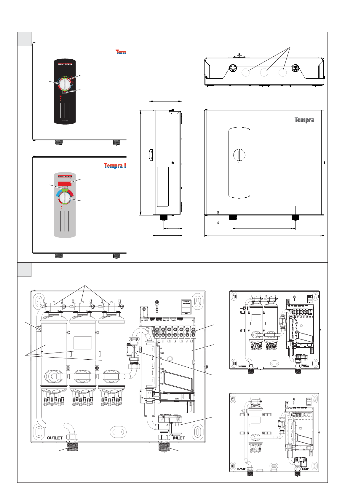
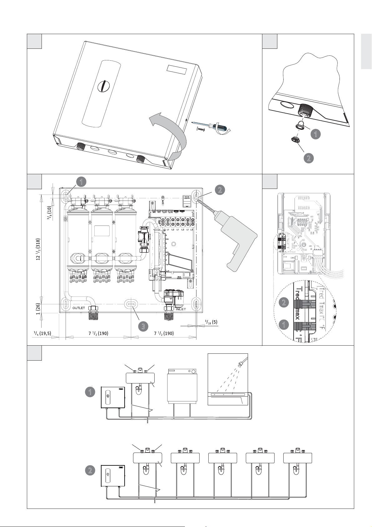
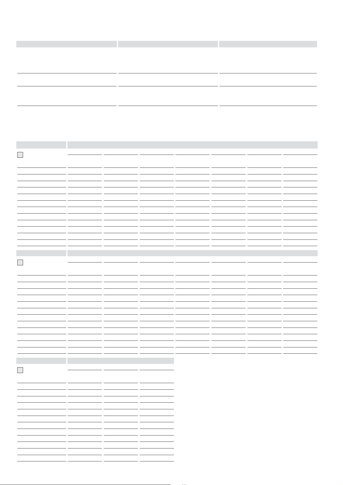
Legend to figures
1 Temperature adjustment knob
2 Temperature scale
2.1 Temperature display
3 "Power" light
4 Knock-outs for wires
5 Safety thermal cut out
6 Outlet temperature sensor
7 Wiring block
8 Electronic control unit
9 Heating system
10 Flow sensor
11 Motor-operated valve
12 Cold water connection
13 Hot water connection
14 Hot valve (left)
15 Cold valve (right)
16 Sink
17 Water supply line for faucet/tap installation
3. General
DANGER: WATER TEMPERATURES OVER 125 °F CAN
!
CAUSE SEVERE BURNS INSTANTLY OR DEATH FROM
SCALDING. A HOT WATER SCALDING POTENTIAL EXISTS
IF THE THERMOSTAT ON THE UNIT IS SET TOO HIGH.
HOUSEHOLDS WITH SMALL CHILDREN, DISABLED OR
ELDERLY PERSONS MAY REQUIRE THAT THE THERMOSTAT
BE SET AT 120 °F OR LOWER TO PREVENT POSSIBLE
INJURY FROM HOT WATER.
The TEMPRA B and TEMPRA Plus units are designed to supply hot water
for a house, apartment or certain commercial applications. Unlike a
conventional storage type water heater the TEMPRA tankless water heater
does not store hot water. Instead, water is heated instantaneously as it
flows through the unit. The TEMPRA offers greater energy efficiency than
storage type water heaters due to the absence of stand-by losses and
reduced hot water pipe runs.
The input of heat into the water is controlled electronically. The TEMPRA
will deliver any water temperature between 86 °F (30 °C) and 140 °F (60 °C).
Please set the desired temperature using the knob on the front cover. The
TEMPRA Plus Temperature adjustment knob can be set to: OFF, 86...140 °F
(30...60 °C).
The TEMPRA B has a °F and a °C scale. The output temperature of the
TEMPRA Plus is shown in the digital display in °F or °C units. (°F or °C units
can be selected during installation, factory setting: °F). The maximum
temperature is electronically limited to 140 °F (60 °C).
For reasons of appliance efficiency and durability (scaling), the
optimum temperature setting lies between 86 °F (30 °C) and
120 °F (50 °C).
The outlet temperature of the TEMPRA Plus can be limited (see "Initial
settings").
TEMPRA B units:
In case the "Power” LED is flashing while the unit operates, the water
flow rate exceeds the heating capacity of the unit. Reduce the hot water
flow rate in order to let the unit achieve the set point temperature.
In case you have questions regarding the way you plan to use the TEMPRA
unit, please call our technical service line at 800-582-8423 (USA and
Canada). For service outside the U.S. and Canada, please call us at USA
413-247-3380. You can also e-mail us at info@stiebel-eltron-usa.com or
fax us at USA 413-247-3369.
The TEMPRA can be used for the following applications.
G
1 Typical residential installation
G
2 Typical commercial installation
4. Mounting the unit
NOTICE: UNIT MUST BE INSTALLED IN A VERTICAL
!
POSITION WITH THE WATER FITTINGS POINTING
DOWNWARD.
WARNING: DO NOT INSTALL UNIT WHERE IT WOULD
ROUTINELY BE SPLASHED WITH WATER. ELECTRIC SHOCK
MAY RESULT.
CAUTION: HOT WATER OUTLET PIPES LEAVING UNIT CAN
BE HOT TO THE TOUCH. INSULATION MUST BE USED FOR
HOT WATER PIPES BELOW 36" DUE TO BURN RISK TO
CHILDREN.
– 7 –
Page 8
NOTICE: THIS UNIT SHOULD NOT BE INSTALLED IN A
!
LOCATION WHERE IT MAY BE EXPOSED TO FREEZING
TEMPERATURES (LESS THAN 36 °F). IF THE UNIT MAY
BE SUBJECT TO FREEZING TEMPERATURES ALL WATER
MUST BE DRAINED FROM THE UNIT. FAILURE TO COMPLY
WITH THIS INSTRUCTION VOIDS ALL WARRANTIES.
THE UNIT SHOULD BE LOCATED IN AN AREA WHERE
WATER LEAKAGE FROM THE UNIT OR CONNECTIONS
WILL NOT RESULT IN DAMAGE TO THE AREA ADJACENT
TO THE UNIT. IF SUCH A LOCATION CANNOT BE AVOIDED
IT IT RECOMMENDED THAT A DRAIN PAN BE INSTALLED
UNDER THE UNIT.
7. The TEMPRA on the hot side is designed for connection to copper
tubing, PEX tubing or a braided stainless steel hose with a
3/4" NPT female tapered thread.
The plumbing on the cold water inlet side needs to be such that
it can easily be removed to allow access to the inlet filter screen.
The easiest way to achieve this is to us a stainless steel
braided hose connector.
If soldering near the unit is necessary, please direct the flame
away from the housing of the unit in order to avoid damage.
8. When all plumbing work is completed, check for leaks and take
corrective action before proceeding.
1. Install TEMPRA as close as possible to the main hot water drawoff points.
2. Install TEMPRA in a frost free area. If frost might occur, remove
unit before freezing temperatures set in.
3. Leave a minimum of 5" of clearance on all sides for servicing.
4. Remove the cover screw with chopper disc and open the cover
C
.
5. Mount unit securely to wall by putting at least three screws
E
through mounting holes
Screws and plastic wall anchors for mounting on masonry or
wood are provided.
1 - 3.
5. Water connections
NOTICE: EXCESSIVE HEAT FROM SOLDERING ON COPPER
!
PIPES NEAR THE TEMPRA MAY CAUSE DAMAGE.
THE COLD WATER CONNECTION TO THE UNIT MUST BE
DISCONNECTED PERIODICALLY IN ORDER TO CLEAN
THE FILTER SCREEN. IT IS REQUIRED TO USE WATER
CONNECTIONS THAT ARE EASILY DETACHABLE SUCH AS
BRAIDED STEEL FLEX CONNECTORS.
NOTICE: HARD WATER OR WATER WITH A HIGH MINERAL
!
COUNT MAY DAMAGE THE UNIT. DAMAGE TO THE UNIT
CAUSED BY SCALE OR A HIGH MINERAL COUNT IS NOT
COVERED UNDER THE WARRANTY.
1. All plumbing work must comply with national and applicable
state and local plumbing codes.
2. A pressure reducing valve must be installed if the cold water
supply pressure exceeds 150 PSI (10 bar).
3. Make certain that the cold water supply line has been flushed
to remove any scale and dirt.
D
Also, the TEMPRA unit has a built in filter screen 1 that
4.
should be cleaned from time to time. Clean screen and put the
2
screen and the washer
5. The cold water connection (inlet) is on the right side of the
unit, and the hot water connection (outlet) is on the left side
of the unit.
6.
NOTICE: TANKLESS WATER HEATERS SUCH AS THE
!
TEMPRA ARE NOT REQUIRED TO BE EQUIPPED WITH
A PRESSURE AND TEMPERATURE RELIEF VALVE
(P&T). IF THE LOCAL INSPECTOR WILL NOT PASS
THE INSTALLATION WITHOUT A P&T, IT SHOULD BE
INSTALLED ON THE HOT WATER OUTLET SIDE OF THE
UNIT.
back into their original position.
6. Electrical connection
WARNING: BEFORE BEGINNING ANY WORK ON THE
!
ELECTRIC INSTALLATION, BE SURE THAT MAIN BREAKER
PANEL SWITCHES ARE "OFF" TO AVOID ANY DANGER OF
ELECTRIC SHOCK. ALL MOUNTING AND PLUMBING MUST
BE COMPLETED BEFORE PROCEEDING WITH ELECTRICAL
HOOK-UP. WHERE REQUIRED BY LOCAL, STATE OR
NATIONAL ELECTRICAL CODES THE CIRCUITS SHOULD
BE EQUIPPED WITH A "GROUND FAULT INTERRUPTER".
THE UNIT MUST BE PROPERLY GROUNDED IN ACCORDANCE
WITH STATE AND LOCAL CODES, OR IN ABSENCE OF SUCH
CODES, IN ACCORDANCE WITH NATIONAL ELECTRIC
CODE OR THE CANADIAN ELECTRIC CODE. FAILURE TO
ELECTRICALLY GROUND THE PRODUCT COULD RESULT IN
SERIOUS PERSONAL INJURY OR DEATH.
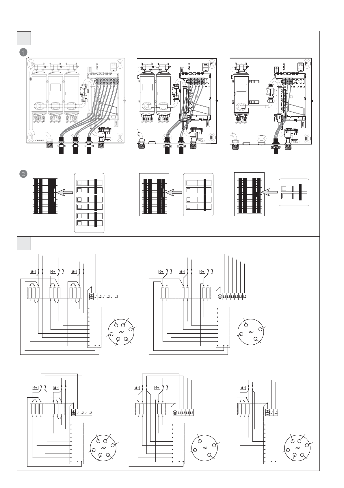
1. All electrical work must comply with national and applicable state
and local electrical codes.
H
The TEMPRA should be connected to properly grounded
2.
dedicated branch circuits of proper voltage rating. Ground must
be brought to the "Ground" at the circuit breaker panel.
TEMPRA 12 B/Plus: These units can be connected to a single circuit.
Use a supply cable protected by a double pole breaker (see
The TEMPRAS 15 to 36 must have multiple power sources.
TEMPRA 15, 20 or 24 B/Plus: These units require two independant
circuits. Use two supply cables protected by two separate double
).
2
I
) .
2
).
15 (380)
A
H
,
1. The "live" wires must
pole breakers (see
TEM PR A 29 o r 3 6 B/ Pl us T hese units require three independant circuits.
Use three supply cables protected by three separate double pole
breakers (see
Please refer to the technical data table for the correct wire and circuit
breaker size. In all cases, make sure that the unit is properly grounded.
3. Cut the electrical connection cable to length and strip.
4. The wire must be fed through the knock-outs located between the
hot and cold water connections
be connected to the slots on the terminal block marked L1 and L2.
The ground wire must be connected to slot marked with the ground
symbol (see
).
2
26_02_02_0893
– 8 –
Page 9
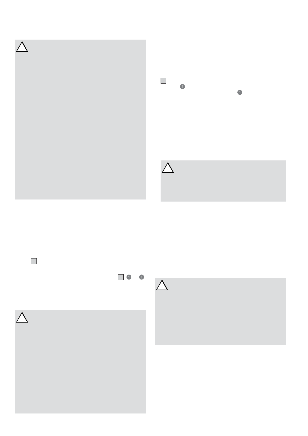
7. Initial settings
Check whether the set value transducer cable is plugged into the
A1 (TEMPRA B) or T
slot T
Soll
F
1 Selection of °F or °C units
D (TEMPRA Plus) on the main PCB.
Soll
- Set jumper on the dial-printed circuit board to °F or °C.
F
2 Activate anti-scalding protection function
-
On the TEMPRA Plus, an anti-scalding protection function can be
activated by two different methods.
1. Limit the outlet temperature to the fixed temperature of 109°F
(43 °C).
- Insert the coding plug into position Tred (reduced temperature).
2. Select a specific outlet temperature
- Switch the appliance 'live'.
/ T
- Open the casing so that coding plug T
becomes accessible.
max
red
- Set the temperature selector to "OFF". The coding plug must be
set to T
- Set coding plug to T
(standard delivery).
max
; the setting mode will be activated and
red
the flashing display shows the current temperature limit.
- Within the next 30 seconds, you can select the required
temperature (display continues to flash). The setting mode will
terminate after 30 seconds; the programming unit will display
"OFF" again.
8. Putting the water heater into
operation
WARNING: OPEN HOT WATER FAUCET FOR A FEW
!
MINUTES UNTIL WATER FLOW IS CONTINUOUS AND ALL
AIR IS PURGED FROM WATER PIPES. THE UNIT’S COVER
MUST BE INSTALLED BEFORE THE CIRCUIT BREAKERS ARE
TURNED ON.
1. Close the cover and fix it using the screw with chopper disc.
2. Turn on circuit breakers to bring electrical power to the unit.
3. Turn the temperature selector clockwise and anti-clockwise, to
calibrate the set value transducer.
4. Adjust the water temperature to the desired level using the knob
on the front cover of the unit.
5. Turn on hot water and wait twenty seconds until temperature
has stabilized.
6. Check the water temperature with your hand and make sure
that it does not feel too hot. Reduce if necessary.
7. Explain to the user how the unit works and familiarise him
or her with its use.
Advise the user about possible hazards (hot water temperature
up to 140 °F / 60 °C). Hand over these instructions, to be kept
for future reference.
9. Normal maintenance
NOTICE: THE TEMPRAS DO NOT CONTAIN ANY PARTS
!
SERVICEABLE BY THE LAY PERSON. IN CASE OF
MALFUNCTION PLEASE CONTACT A LICENSED PLUMBER
OR ELECTRICIAN.
STIEBEL ELTRON TEMPRA tankless water heaters are designed
for a very long service life. Actual life expectancy will vary with
water quality and use. The unit itself does not require any regular
maintenance. However, to ensure consistent water flow, it is
recommended to periodically remove scale and dirt that may build
up at the aerator of the faucet(s), the filter screen in the unit, or
in the shower head.
English
10. Technical Data
Model `BTVŨĜŝ `BTVŨĜÑ `BTVŨŝƃ `BTVŨŝÔ `BTVŨŝĎ `BTVŨŗō
Mat. no. ŝŝŗÔŝƃ ŝŝŗÔŝĜ ŝŝŗÔŝŝ ŝŝŗÔŝÔ ŝŗŝÄÄÑ ŝŗŝÄÄō
Model `BTVŨĜŝŨTùşń `BTVŨĜÑŨTùşń `BTVŨŝƃŨTùşń `BTVŨŝÔŨTùşń `BTVŨŝĎŨTùşń `BTVŨŗōŨTùşń
Mat. no. ŝŝÔĜĎō ŝŝÔĜĎŌ ŝŝÔĜĎÄ ŝŝÔĜĎĎ ŝŝŗÔŝÑ ŝŝŗÔŝō
Phase 1 1 1 1 1 1
Voltage V 208 240 208 240 208 240 208 240 208 240 208 240
Wattage kW 9 12 10.8 14.4 14.4 19.2 18 24 21.6 28.8 27 36
Max. amp, load A 44 50 2 x 26 2 x 30 2 x 35 2 x 40 2 x 44 2 x 50 3 x 35 3 x 40 3 x 44 3 x 50
Min. required circuit
breaker size
Required wire size AWG COPPER 6 6 2 x 8 2 x 8 2 x 8 2 x 8 2 x 6 2 x 6 3 x 8 3 x 8 3 x 6 3 x 6
Inlet temperature, max. °F (°C) 131 (55)
Water flow to activate unit tGPM (tl/min) 0.37 (1.4) 0.50 (1.9) 0.50 (1.9) 0.50 (1.9) 0.77 (2.9) 0.77 (2.9)
Nominal water volume GAL (l) 0.13 (0.5) 0.26 (1.0) 0.26 (1.0) 0.26 (1.0) 0.39 (1.5) 0.39 (1.5)
Working pressure, max. PSI (bar) 145 (10)
Tested to pressure PSI (bar) 290 (20)
Weight lbs. (kg) 13.5 (6.1) 16.1 (7.3) 16.1 (7.3) 16.1 (7.3) 19.0 (8.6) 19.0 (8.6)
Dimensions
height
depth
width
Water connections NPT 3/4"
– Tankless water heaters are considered a non-continuous load – Conductors should be sized to maintain a voltage drop of less than 3 % under load
A 60 60 2 x 40 2 x 40 2 x 50 2 x 50 2 x 60 2 x 60 3 x 50 3 x 50 3 x 60 3 x 60
inch (mm)
14 1/2 (369)
4 5/8 (117)
16 5/8 (420)
– 9 –
Page 10
11. Troubleshooting
Symptom TĒńńêù¼|şń¼ ZĒùşŒ êĒĉ
No hot water
Not enough hot water – filter screen clogged – clean filter screen at unit
– circuit breakers off
– safety thermal cut-out tripped
– not enough flow rate to activate unit
– turn circuit breakers on
– reset safety thermal cut-out
– clean filter screen at unit
– clean faucet aerator or shower head
Water not hot enough
– water flow rate too high
– voltage too low
– reduce water flow rate until power light on front
cover stops blinking
– supply correct voltage to unit
If you are not able to resolve a problem please contact us toll free at 800-582-8423 before removing the unit from the wall.
STIEBEL ELTRON is happy to provide technical assistance. In most instances, we can resolve the problem over the phone.
12. Spare parts
Model Spare part No.
J
TEMPRA 12 B 286356 254307 279998 286360 286369 286366 286461
TEMPRA 15 B 286356 254307 279997 286361 286369 286844 286461
TEMPRA 20 B 286356 254307 279997 286362 286369 286844 286461
TEMPRA 24 B 286356 254307 279997 286364 286369 286367 286461
TEMPRA 29 B 286356 254307 279996 286373 286369 296888 286461
TEMPRA 36 B 286356 254307 279996 286374 286369 296889 286461
TEMPRA 12 Plus 286370 254307 279998 286360 286369 286375 286461
TEMPRA 15 Plus 286370 254307 279997 286361 286369 286845 286461
TEMPRA 20 Plus 286370 254307 279997 286362 286369 286845 286461
TEMPRA 24 Plus 286370 254307 279997 286364 286369 286376 286461
TEMPRA 29 Plus 286370 254307 279996 286373 286369 286378 286461
TEMPRA 36 Plus 286370 254307 279996 286374 286369 286379 286461
Model Spare part No.
J
TEMPRA 12 B 278698 --- 286359 --- 280677 056755 280730
TEMPRA 15 B 278698 --- 286359 --- 280677 056755 280730
TEMPRA 20 B 278698 --- 286359 --- 280677 056755 280730
TEMPRA 24 B 278698 --- 286359 --- 280677 056755 280730
TEMPRA 29 B 278698 --- 286359 --- 280677 056755 280730
TEMPRA 36 B 278698 --- 286359 --- 280677 056755 280730
TEMPRA 12 Plus 278698 220502 286372 283455 280677 056755 280730
TEMPRA 15 Plus 278698 220502 286372 283455 280677 056755 280730
TEMPRA 20 Plus 278698 220502 286372 283455 280677 056755 280730
TEMPRA 24 Plus 278698 220502 286372 283455 280677 056755 280730
TEMPRA 29 Plus 278698 220502 286372 283455 280677 056755 280730
TEMPRA 36 Plus 278698 220502 286372 283455 280677 056755 280730
1 2 3 4 5 6 7
Housing
8 9 10 11 12 13 14
Plumbing
connection 3/4"
Temp. control
knob
Advanced Flow
Control
Wiring block Heating system Safety thermal
cut out
Electronic temp.
control
Jumpers Temperature
sensor
Electronic control
device
Filter screen Set point case
Flow sensor
Model Spare part No.
J
TEMPRA 12 B 278695 --- 254312
TEMPRA 15 B 278695 --- 254312
TEMPRA 20 B 278695 --- 254312
TEMPRA 24 B 278695 --- 254312
TEMPRA 29 B 278695 --- 254312
TEMPRA 36 B 278695 --- 254312
TEMPRA 12 Plus --- 280622 254312
TEMPRA 15 Plus --- 280622 254312
TEMPRA 20 Plus --- 280622 254312
TEMPRA 24 Plus --- 280622 254312
TEMPRA 29 Plus --- 280622 254312
TEMPRA 36 Plus --- 280622 254312
15 16 17
Inlet pipe elbow Valve assembly Axis connection
plug
– 10 –
Page 11

J
12
5
3
6
7
4
9
English
Tempra
Tempra
Plus
16
8
13
8
17
15
14
Tempra
Tempra
Plus
l
Tempra
Tempra
10
11
0
1
2
i
13. Warranty
WARRANTY
RESIDENTIAL & COMMERCIAL WARRANTY: STIEBEL ELTRON WARRANTS TO THE ORIGINAL OWNER THAT THE INSTANTANEOUS
WATER HEATER WILL BE FREE FROM DEFECTS IN WORKMANSHIP AND MATERIALS FOR A PERIOD OF THREE YEARS FROM THE
DATE OF PURCHASE. SHOULD THE PART(S) PROVE TO BE DEFECTIVE UNDER NORMAL USE DURING THIS PERIOD, STIEBEL ELTRON,
INC. WILL BE RESPONSIBLE FOR REPLACEMENT OF THE DEFECTIVE PART(S) ONLY. STIEBEL ELTRON, INC. IS NOT RESPONSIBLE FOR
LABOR CHARGES TO REMOVE AND/OR REPLACE THE DEFECTIVE PART(S), OR ANY INCIDENTIAL OR CONSEQUENTIAL EXPENSES.
SHOULD THE OWNER WISH TO RETURN THE INSTANTANEOUS WATER HEATER FOR REPAIR, THE OWNER MUST FIRST SECURE
WRITTEN AUTHORIZATION FROM STIEBEL ELTRON, INC. THE OWNER SHALL BE REQUIRED TO SHOW PROOF OF PURCHASE DATE,
AND TO PAY ALL TRANSPORTATION COSTS TO RETURN THE DEFECTIVE PART(S) OR INSTANTANEOUS WATER HEATER FOR REPAIR
OR REPLACEMENT. WARRANTY IS VOID IF WATER HEATER HAS BEEN INSTALLED OR USED IMPROPERLY OR IF DESIGN HAS BEEN
ALTERED IN ANY WAY.
STIEBEL ELTRON, INC.
17 West Street
West Hatfield, MA 01088, USA
PHONE: 800-582-8423 or 413-247-3380
FAX: 413-247-3369
E-Mail info@stiebel-eltron-usa.com
www.stiebel-eltron-usa.com
26_02_02_0977
– 11 –
Page 12

ESPAÑOL ÍNDICE DE MATERIAS
1. General Information ___________________________________________ 12
2. Aumento máximo de temperatura del agua fría entrante _ 13
3. Generalidades __________________________________________________ 17
4. Montaje de la unidad __________________________________________ 18
5. Conexiones de agua ____________________________________________ 18
6. Conexión eléctrica______________________________________________ 18
7. Ajustes iniciales ________________________________________________ 19
8. Puesta en servicio del calentador de agua __________________ 19
9. Mantenimiento normal ________________________________________ 19
10. Datos técnicos __________________________________________________ 20
11. Solución de problemas ________________________________________ 20
12. Garantía _________________________________________________________ 20
13. Repuestos _______________________________________________________ 21
S1 Safety Precautions
FAVOR LEER Y CUMPLIR CUIDADOSAMENTE TODAS
!
LAS INDICACIONES DEL PRESENTE MANUAL DE
SERVICIO. DE NO SEGUIR LAS INDICACIONES,
NORMAS Y REGLAS DETALLADAS SE PUEDEN CAUSAR
DAÑOS PERSONALES Y/O LA MUERTE.
LA INSTALACIÓN DE ESTA UNIDAD DEBE SER EFECTUADA
POR UN ELECTRICISTA Y PLOMERO PROFESIONAL. UNA
VEZ TERMINADA LA INSTALACIÓN DEBE CUMPLIR CON
TODAS LAS NORMAS Y CÓDIGOS LOCALES Y NACIONALES.
EL MANTENIMIENTO O REPARACIÓN DE ESTA UNIDAD
DEBE SER EFECTUADO POR UN TÉCNICO DEBIDAMENTE
CALIFICADO PARA EFECTUAR TAL SERVICIO.
HAY QUE DESCONECTAR / APAGAR TODOS LOS
INTERRUPTORES AUTOMÁTICOS, “BREAKERS”,
DISYUNTORES, Y CONEXIONES DANDO CARGA ELÉCTRICA
A LA UNIDAD ANTES DE PROCEDER CON CUALQUIER
INSTALACIÓN, AJUSTE, CAMBIO O PROCEDIMIENTO DE
SERVICIO. EL NO SEGUIR ESTE PROCESO SE CORRE LA
POSIBILIDAD DE LESIONES PERSONALES Y PELIGROS QUE
PUEDEN CAUSAR HASTA LA MUERTE.
NO SE PUEDE ABRIR O DESTAPAR LA UNIDAD A MENOS
QUE LA ELECTRICIDAD ALIMENTANDO LA UNIDAD ESTÁ
APAGADA. EL NO SEGUIR ESTE PROCESO SE CORRE LA
POSIBILIDAD DE LESIONES PERSONALES Y PELIGROS QUE
PUEDEN CAUSAR HASTA LA MUERTE.
1. General Information
Es importante leer y cumplir cuidadosamente todas las indicaciones
del presente manual de servicio. De no seguir las indicaciones,
normas y reglas detalladas se pueden causar daños personal y/o
materiales. Errores, cambios de lo indicado en la instalación,
ajuste, alteraciones, tipo de servicio y uso de esta unidad pueden
provocar serios daños personales.
Se requiere que la instalación de esta unidad sea efectuada por
un electricista y plomero profesionales. Una vez terminada la
instalación debe cumplir con todas las normas y códigos locales
y nacionales. La adecuada instalación es responsabilidad del
usuario. El no cumplir con las instrucciones de instalación o el
uso inapropiado anula la garantía.
Este manual de instrucciones debe estar guardado para referencia.
El contratista instalador debe dejar este manual con el dueño/
usuario del equipo.
Si hay alguna(s) pregunta(s) sobre la instalación, uso o
funcionamiento de este calentador de agua, o si se requieren
copias adicionales de este manual, favor llamar a nuestro teléfono
de ser vicio (800) 582-8423 (solo en los EE.UU.AA y Canadá). Si Ud.
está ubicado afuera de los EE.UU.AA. y Canadá favor llamarnos al
teléfono ++ (413) 247-3380 y nosotros les dirigimos al centro de
servicio Stiebel Eltron autorizado más cercano.
ES INDISPENSABLE CONECTAR EL APARATO A LA TOMA
DE TIERR A DE LA INSTAL ACIÓN ELÉC TRIC A. EL NO SEGUIR
ESTE PROCESO SE CORRE LA POSIBILIDAD DE LESIONES
PERSONALES Y PELIGROS QUE PUEDEN CAUSAR HASTA
LA MUERTE.
AGUA CALIENTE CON TEMPERATURA MAYOR DE 125°
F / 52° C PUEDE CAUSAR QUEMADURAS GRAVES DE
ESCALDADURA INSTANTÁNEAMENTE Y/O LA MUERTE.
EL RIESGO PARA QUEMADURAS DE ESCALDADURA
EXISTE SI EL CONTROL DEL TERMOSTATO DE LA UNIDAD
ESTA PUESTO EN UNA POSICIÓN DEMASIADO ALTA.
HOGARES CON INFANTES, NIÑOS PEQUEÑOS, PERSONAS
MINUSVÁLIDAS O ANCIANOS DEBEN OPTAR POR COLOCAR
LA TEMPERATURA DE AGUA CALIENTE SALIENTE A MENOS
DE 120° F (49° C) PARA EVITAR POSIBLES LESIONES POR
QUEMADURA.
ESTE ES EL SIMBOLO / ADVERTENCIA DE SEGURIDAD!!!
!
SE UTILIZA PARA ALERTARLES DE RIESGOS Y PELIGROS
POTENCIALES REFERENTES A SU SEGURIDAD PERSONAL,
HAY QUE SEGUIR TODOS LOS MENSAJES DE ADVERTENCIA
PARA EVITAR POSIBLES LESIONES PERSONALES Y
PELIGROS QUE PUEDEN CAUSAR HASTA LA MUERTE.
– 12 –
Page 13

2. Aumento máximo de temperatura del agua fría entrante
Aumento máximo de temperatura del agua fría entrante
Flujo de agua caliente
GPM l/min
Temperatura del agua caliente
105 °F 40 °C
agua fría temperatura de entrada °F °C
39 59 77 95 113 131 4 15 25 35 45 55
TEMPRA 12 B / TEMPRA 12 Plus @ 208 V 9 kW 0,95 1,36 2,27 6,61 3,58 5,16 8,59 25,00
@ 220 - 240 V 12 kW 1,26 1,82 3,03 6,61 4,77 6,87 11,46 25,00
TEMPRA 15 B / TEMPRA 15 Plus @ 208 V 10,8 kW 1,14 1,63 2,72 6,61 4,30 6,19 10,31 25,00
@ 220 - 240 V 14.4 kW 1,51 2,18 3,63 6,61 5,73 8,25 13,75 25,00
TEMPRA 20 B / TEMPRA 20 Plus @ 208 V 14.4 kW 1,51 2,18 3,63 6,61 5,73 8,25 13,75 25,00
@ 220 - 240 V 19.2 kW 2,02 2,91 4,84 6,61 7,64 11,00 18,33 25,00
TEMPRA 24 B / TEMPRA 24 Plus @ 208 V 18 kW 1,89 2,72 4,54 6,61 7,16 10,31 17,18 25,00
@ 220 - 240 V 24 kW 2,52 3,63 6,05 6,61 9,55 13,75 22,91 25,00
TEMPRA 29 B / TEMPRA 29 Plus @ 208 V 21.6 kW 2,27 3,27 5,45 6,61 8,59 12,37 20,62 25,00
@ 220 - 240 V 28.8 kW 3,03 4,36 6,61 6,61 11,46 16,50 25,00 25,00
TEMPRA 36 B / TEMPRA 36 Plus @ 208 V 27 kW 2,84 4,09 6,61 6,61 10,74 15,47 25,00 25,00
@ 220 - 240 V 36 kW 3,78 5,45 6,61 6,61 14,32 20,62 25,00 25,00
Temperatura del agua caliente
agua fría temperatura de entrada °F °C
39 59 77 95 113 131 4 15 25 35 45 55
TEMPRA 12 B / TEMPRA 12 Plus @ 208 V 9 kW 0,83 1,14 1,70 3,41 6,61 3,14 4,30 6,44 12,89 25,00
@ 220 - 240 V 12 kW 1,11 1,51 2,27 4,54 6,61 4,19 5,73 8,59 17,18 25,00
TEMPRA 15 B / TEMPRA 15 Plus @ 208 V 10,8 kW 1,00 1,36 2,04 4,09 6,61 3,77 5,16 7,73 15,47 25,00
@ 220 - 240 V 14.4 kW 1,33 1,82 2,72 5,45 6,61 5,03 6,87 10,31 20,62 25,00
TEMPRA 20 B / TEMPRA 20 Plus @ 208 V 14.4 kW 1,33 1,82 2,72 5,45 6,61 5,03 6,87 10,31 20,62 25,00
@ 220 - 240 V 19.2 kW 1,77 2,42 3,63 6,61 6,61 6,71 9,16 13,75 25,00 25,00
TEMPRA 24 B / TEMPRA 24 Plus @ 208 V 18 kW 1,66 2,27 3,41 6,61 6,61 6,29 8,59 12,89 25,00 25,00
@ 220 - 240 V 24 kW 2,21 3,03 4,54 6,61 6,61 8,38 11,46 17,18 25,00 25,00
TEMPRA 29 B / TEMPRA 29 Plus @ 208 V 21.6 kW 1,99 2,72 4,09 6,61 6,61 7,54 10,31 15,47 25,00 25,00
@ 220 - 240 V 28.8 kW 2,66 3,63 5,45 6,61 6,61 10,06 13,75 20,62 25,00 25,00
TEMPRA 36 B / TEMPRA 36 Plus @ 208 V 27 kW 2,49 3,41 5,11 6,61 6,61 9,43 12,89 19,33 25,00 25,00
@ 220 - 240 V 36 kW 3,32 4,54 6,61 6,61 6,61 12,57 17,18 25,00 25,00 25,00
113 °F 45 °C
Español
Temperatura del agua caliente
agua fría temperatura de entrada °F °C
39 59 77 95 113 131 4 15 25 35 45 55
TEMPRA 12 B / TEMPRA 12 Plus @ 208 V 9 kW 0.61 0.76 0.97 1.36 2.27 6.61 2.30 2.86 3.68 5.16 8.59 25.00
@ 220 - 240 V 12 kW 0.81 1.01 1.30 1.82 3.03 6.61 3.07 3.82 4.91 6.87 11.46 25.00
TEMPRA 15 B / TEMPRA 15 Plus @ 208 V 10,8 kW 0.73 0.91 1.17 1.63 2.72 6.61 2.76 3.44 4.42 6.19 10.31 25.00
@ 220 - 240 V 14.4 kW 0.97 1.21 1.56 2.18 3.63 6.61 3.68 4.58 5.89 8.25 13.75 25.00
TEMPRA 20 B / TEMPRA 20 Plus @ 208 V 14.4 kW 0.97 1.21 1.56 2.18 3.63 6.61 3.68 4.58 5.89 8.25 13.75 25.00
@ 220 - 240 V 19.2 kW 1.30 1.61 2.08 2.91 4.84 6.61 4.91 6.11 7.86 11.00 18.33 25.00
TEMPRA 24 B / TEMPRA 24 Plus @ 208 V 18 kW 1.22 1.51 1.95 2.72 4.54 6.61 4.60 5.73 7.36 10.31 17.18 25.00
@ 220 - 240 V 24 kW 1.62 2.02 2.59 3.63 6.05 6.61 6.14 7.64 9.82 13.75 22.91 25.00
TEMPRA 29 B / TEMPRA 29 Plus @ 208 V 21.6 kW 1.46 1.82 2.33 3.27 5.45 6.61 5.52 6.87 8.84 12.37 20.62 25.00
@ 220 - 240 V 28.8 kW 1.95 2.42 3.11 4.36 6.61 6.61 7.36 9.16 11.78 16.50 25.00 25.00
TEMPRA 36 B / TEMPRA 36 Plus @ 208 V 27 kW 1.82 2.27 2.92 4.09 6.61 6.61 6.90 8.59 11.05 15.47 25.00 25.00
@ 220 - 240 V 36 kW 2.43 3.03 3.89 5.45 6.61 6.61 9.21 11.46 14.73 20.62 25.00 25.00
140 °F 60 °C
– 13 –
Page 14

A
A
A
TEMPRA 12 - 36 B
4
Tankless Electric Water Heater
with electronic temperature control
i
a
t
n
l
e
U
d
s
i
e
s
e
R
|
|
C
o
g
n
i
h
s
a
W
d
n
a
H
1
°F °C
2
m
S
m
C
A
e
L
D
r
I
c
N
i
G
a
D
l
A
O
N
G
n
E
l
R
y
3
Blinking: maximum power,
less than set point temp.
Steady: unit operating
Off: unit off
4 5/8 (117)
TEMPRA 12 - 36 Plus
(369)
2
/
1
14
Tankless Electric Water Heater
with electronic temperature control
3
Power
e
d
i
s
e
R
g
n
i
h
s
a
W
d
n
a
H
On: unit operating
Off: unit off
2.1
t
n
i
a
l
U
s
e
C
o
m
m
S
C
A
e
L
r
D
c
I
N
i
G
a
D
l
A
O
N
n
G
E
l
y
R
1
(17,5)
16
/
11
B
6
9
Made in Germany
8 5/8 (220)2 9/16 (65)
5
16
/8 (420)4 (102)
26_02_02_0875
TEMPRA 29, 36 B
5
TEMPRA 29, 36 Plus
TEMPRA 15, 20, 24 B
TEMPRA 15, 20, 24 Plus
26_02_02_0874
7
8
10
TEMPRA 12 B / TEMPRA 12 Plus
11
– 14 –
12
26_02_02_0873
26_02_02_0873 26_02_02_0873
13
Page 15

C
D
Español
1
2
26_02_02_0876
26_02_02_0877
E
G
1
F
2
2
3
26_02_02_0872
1514
1
26_02_02_0940
1
2
16
17
1514
16
17
26_02_02_0878
– 15 –
Page 16

H
TEMPRA 29, 36 B
TEMPRA 29, 36 Plus
1
TEMPRA 15, 20, 24 B
TEMPRA 15, 20, 24 Plus
TEMPRA 12 B
TEMPRA 12 Plus
2
TEMPRA 36 B
I
TEMPRA 36 Plus
642
531
CKT 1
642
531
26_02_02_0881
CKT 3 CKT 1 CKT 2 CKT 1
CKT 2
ON
OFF
ON
OFF
ON
OFF
ON
OFF
ON
OFF
ON
OFF
OFF
OFF
OFF
OFF
26_02_02_0568
26_02_02_0881
ON
ON
ON
ON
26_02_02_0568
TEMPRA 29 B
TEMPRA 29 Plus
642
531
6
11/1 2
5
4
9/10
3
2
7/8
1
13
CKT 1
14 15
CKT 2
1
CKT 3
4
42
51
42
51
6
2
5
3
42
51
6
11/1 2
5
4
9/10
3
2
7/8
1
13
CKT 1
14 15
CKT 2
1
CKT 3
4
26_02_02_0881
ON
OFF
ON
OFF
26_02_02_0568
2
5
TEMPRA 24 B
TEMPRA 24 Plus
642
531
642
531
TEMPRA 15/20 B
TEMPRA 15/20 Plus
42
CKT 1
CKT 2
6
11/1 2
5
4
9/10
3
2
7/8
1
14 15 14 15 14 15
13
4
6
2
1
5
3
51
42
51
6
11/1 2
5
4
9/10
3
2
7/8
1
13
CKT 1
CKT 2
4
1
5
TEMPRA 12 B
TEMPRA 12 Plus
642
531
2
– 16 –
6
11/1 2
5
4
9/10
3
2
7/8
1
13
CKT 1
4
6
2
1
3
5
85_02_02_0001
Page 17

LEA ATENTAMENTE ESTE MANUAL ANTES DE INSTALAR EL CALENTADOR DE AGUA TEMPRA. SI NO SIGUE LAS
NORMAS DE SEGURIDAD O LAS INSTRUCCIONES DEL PRESENTE MANUAL ES POSIBLE QUE LA UNIDAD NO
FUNCIONE ADECUADAMENTE Y PODRÍAN PRODUCIRSE DAÑOS MATERIALES, LESIONES CORPORALES GRAVES
E INCLUSO LA MUERTE.
STIEBEL ELTRON, INC. NO SE HACE RESPONSABLE DE NINGÚN DAÑO CAUSADO POR EL INCUMPLIMIENTO DE LAS
INSTRUCCIONES DE INSTALACIÓN Y OPERACIÓN INDICADAS EN EL PRESENTE MANUAL O DERIVADO DEL USO
INDEBIDO DE LA INSTALACIÓN. EL USO INDEBIDO ABARCA EL USO DE LA PRESENTE INSTALACIÓN PARA CALENTAR
CUALQUIER OTRO LÍQUIDO DISTINTO AL AGUA. SI NO OBSERVA LAS INSTRUCCIONES DE INSTALACIÓN Y OPERACIÓN
O SE HACE USO INDEBIDO DE LA INSTALACIÓN LA GARANTÍA QUEDARÁ ANULADA. NUNCA DEBE EXTRAER LA
TAPA DE LA UNIDAD A MENOS QUE SE HAYA CORTADO ANTES LA ALIMENTACIÓN ELÉCTRICA.
ANTE CUALQUIER DUDA RELACIONADA CON LA INSTALACIÓN U OPERACIÓN DEL PRESENTE CALENTADOR DE AGUA
O SI NECESITA CUALQUIER MANUAL DE INSTALACIÓN ADICIONAL, CONSULTE AL SERVICIO TÉCNICO EN EL NÚMERO
800-582-8423 (SÓLO EE.UU. Y CANADÁ) SI LLAMA DESDE FUERA DE LOS EE.UU. O CANADÁ LLAME AL NÚMERO
DE LOS EE.UU. 413-247-3380 Y LE REMITIREMOS A UN REPRESENTANTE CUALIFICADO DE SERVICIO TÉCNICO
STIEBEL ELTRON DE SU LOCALIDAD.
Español
Leyenda de cifras
1 Botón de ajuste de temperatura
2 Escala de temperatura
2.1 Pantalla de temperatura
3 Luz de alimentación
4 Orificios ciegos para cables
5 Disparo de la protección térmica de seguridad
6 Sensor de temperatura de salida
7 Bloque de cableado
8 Unidad de control electrónica
9 Sistema de calefacción
10 Sensor de flujo
11 Valvula motorizada
12 Conexión de agua fría
13 Conexión de agua caliente
14 Válvula del circuito de agua caliente (izquierda)
15 Válvula del circuito de agua fría (derecha)
16 Sumidero
17 Tubería de suministro de agua para instalación con grifo
3. Generalidades
PELIGRO: AGUA CALIENTE CON TEMPERATURA MAYOR
!
DE 125 °F / 52 °C PUEDE C AUSAR QUEM ADURAS GRAVES
DE ESCALDADURA INSTANTÁNEAMENTE Y/O LA MUERTE.
EL RIESGO PARA QUEMADURAS DE ESCALDADURA
EXISTE SI EL CONTROL DEL TERMOSTATO DE LA UNIDAD
ESTA PUESTO EN UNA POSICIÓN DEMASIADO ALTA.
HOGARES CON INFANTES, NIÑOS PEQUEÑOS, PERSONAS
MINUSVÁLIDAS O ANCIANOS DEBEN OPTAR POR COLOCAR
LA TEMPERATURA DE AGUA CALIENTE SALIENTE A MENOS
DE 120 °F (49 °C) PARA EVITAR POSIBLES LESIONES POR
QUEMADURA.
Las unidades TEMPRA B y TEMPRA Plus han sido diseñadas
para suministrar agua caliente para viviendas unifamiliares,
apartamentos o determinadas aplicaciones comerciales.
La entrada de calor en el agua se controla electrónicamente. El
TEMPRAS es capaz de proporcionar cualquier temperatura del
agua entre 86 °F (30 °C) y 140 °F (60 °C). Ajuste la temperatura
deseada utilizando el botón del panel delantero. El botón de ajuste
de temperatura TEMPRA Plus puede ajustarse en: OFF, 86...140 °F
(30...60 °C).
El TEMPRA B posee una escala en °F y °C. La temperatura de salida
del TEMPRA Plus se muestra en la pantalla digital en °F o °C. (las
unidades °F o °C pueden seleccionarse durante la instalación y de
fábrica viene ajustada la unidad °F). La temperatura máxima está
limitada electrónicamente a 140 °F (60 °C).
Por razones de eficiencia y vida útil (calcificación) del aparato, el
rango de ajuste óptimo de la temperatura está entre 30°C (86°F)
y 50°C (120°F).
La temperatura de salida del TEMPRA Plus puede limitarse (véase
"Ajustes iniciales").
TEMPRA B dispositivo:
Si el LED "Power" [alimentación] parpadea durante el
funcionamiento de la unidad, el caudal de agua supera la
capacidad de calefacción de la unidad. Reduzca el caudal de agua
caliente para que la unidad alcance la temperatura de consigna.
Si tiene cualquier duda sobre la utilización del TEMPRAS llame
a nuestro servicio técnico 800-582-8423 (EE.UU. y Canadá). Para
recibir servicio técnico fuera de los EE. UU. y Canadá, llámenos en
USA 413-247-3380. También puede enviarnos un e-mail a la dirección
info@stiebel-eltron-usa.com o un fax a los EE. UU. 413-247-3369.
El TEMPRA puede utilizarse para las siguientes aplicaciones.
G
1 Instalación residencial típica
G
2 Instalación comercial típica
A diferencia del acumulador convencional, el calentador de agua
sin depósito TEMPRAS no almacena agua caliente. En lugar de
ello, el agua se calienta de forma instantánea a medida que pasa
a través de la unidad. El TEMPRAS ofrece mayor rendimiento
energético que los calentadores de agua de almacenamiento,
debido a la ausencia de pérdidas en stand-by y a unas longitudes
menores de tubería de agua caliente.
– 17 –
Page 18
4. Montaje de la unidad
NOTA: LA UNIDAD DEBE ESTAR INSTALADA EN POSICIÓN
!
VERTICAL CON LAS CONEXIONES DE AGUA MIRANDO
HACIA ABAJO. NO INSTALE LA UNIDAD EN LUGARES EN
LOS QUE PUEDA SUFRIR SALPICADURAS DE AGUA. PUEDE
SUFRIR UNA ELECTROCUCIÓN.
PELIGRO: NO SE PUEDE INSTALAR LA UNIDAD EN UN SITIO
DONDE HAY SALPICADURA DE AGUA. ES PARA EVITAR EL
RIESGO DE POSIBLE DESCARGA ELECTRICA.
PRECAUCION IMPORTANTE: LA TUBERIA SALIENTE DE
LA UNIDAD PUEDE ESTAR CALIENTE AL TOCARLA. LOS
TUBOS CON UNA ALTURA DE 36 PULGADAS (90 CM) O
MENOS TIENEN QUE SER RECUBIERTOS CON INSULACION
TERMICA PARA EVITAR QUEMADURAS A LOS NIÑOS.
AVISO IMPORTANTE: NO SE PUEDE INSTALAR LA UNIDAD
EN UN SITIO DONDE ESTE SUJETO A TEMPERATURAS
MENORES DE CERO °C (32 °F). SI LA UNIDAD ESTA SUJETA
A TEMPERATURAS QUE PERMITIRIAN LA CONGELACION
DEL AGUA HAY QUE DRENAR LA UNIDAD ANTES QUE
OCURRA TAL COSA. SI ESTO NO SE HACE EL CALENTADOR
PIERDE LA GARANTIA.
HAY QUE INSTALAR LA UNIDAD DONDE SE EVITE QUE
UNA POSIBLE FUGA DE AGUA DESDE LA UNIDAD O SUS
CONEXCIONES PUEDAN RESULTAR EN DAÑOS A LAS
AREAS CONTIGUAS. SI NO ES POSIBLE TAL COLOCACION
RECOMENDAMOS COLOCAR / INSTALAR DRENAJE POR
DEBAJO DE LA UNIDAD.
1. Todos los trabajos de fontanería deben cumplir la normativa
nacional, regional y local en materia de fontanería.
2. Si la presión de suministro de agua fría supera los 150 PSI
(10 bar) deberá instalarse una válvula reductora de presión.
3. Asegúrese de que la tubería de suministro de agua caliente
se ha enjuagado para eliminar cualquier tipo de residuos y
suciedad.
Asimismo, el TEMPRAS dispone de una pantalla de filtrado
4.
D
1
integrada
y vuelva a colocar la pantalla y la arandela
La conexion de agua fria a la unidad esta sujeta a ser
desconectada periodicamente par poder limpar el pequeño
filtro / malla que se encuentra adentro de la misma. Sugerimos
utilizar conexiones, uniones de tope y mangueras flexibles,
resistentes al agua caliente, que permitan hacer tal servicio
de mantenimiento preventivo.
5. La conexión de agua fría (entrada) se encuentra a la derecha de
la unidad y la conexión de agua caliente (salida) a la izquierda
de la unidad.
6.
!
que debe limpiarse periódicamente. Lave la pantalla
1
en su posición original.
NOTA: LOS CALENTADORES DE AGUA SIN DEPÓSITO,
COMO EL TEMPRA, NO NECESITAN ESTAR EQUIPADOS
CON UNA VÁLVULA DE ALIVIO DE PRESIÓN Y
TEMPERATURA (P&T). SI EL INSPECTOR LOCAL NO
PASA LA INSTALACIÓN SIN UNA VÁLVULA P&T, ÉSTA
DEBE INSTALARSE EN EL LADO DE SALIDA DE AGUA
CALIENTE DE LA UNIDAD.
1. Instale el TEMPRA lo más cerca posible de los puntos de
suministro de agua caliente.
2. Instale el TEMPRA en una zona resguardada de la escarcha.
Si se formara escarcha, extraiga la unidad antes de que se
impongan las temperaturas de congelación.
3. Deje una distancia de separación mínima de 5" por todos los
lados para poder realizar el mantenimiento sin problemas.
4. Extraiga el tornillo de la tapa con disco interruptor y abra la
5. Instale la unidad fijamente a la pared colocando al menos
C
tapa
tres tornillos en los orificios de montaje
Los tornillos y los dispositivos de anclaje plásticos de pared
para montar sobre mampostería o madera vienen incluidos.
.
E
1 - 1.
5. Conexiones de agua
NOTA: UN CALOR DE SOLDADURA EXCESIVO SOBRE
!
LAS TUBERÍAS DE COBRE JUNTO AL ZZTEMPRA PODRÍA
CAUSAR DAÑOS.
LA CONEXCION DE AGUA FRIA A LA UNIDAD ESTA SUJETA
A SER DESCONECTADA PERIODICAMENTE PAR PODER
LIMPIAR EL PEQUEÑO FILTRO / MALLA QUE SE ENCUENTRA
ADENTRO DE LA MISMA. SUGERIMOS UTILIZAR
CONEXIONE S, UNIONES DE TOPE Y MANGU ERAS FLEXIBLE S,
RESISTENTES AL AGUA CALIENTE, QUE PERMITAN
HACER TAL SERVICIO DE MANTENIMIENTO PREVENTIVO.
ATENCION: HAY QUE TOMAR EN CUENTA QUE LA
INSTALACION DE LA UNIDAD EN LUGARES DONDE
HAY “AGUA DURA” O AGUA CON UN ALTO CONTENIDO
DE MINERALES SE TOMA UN RIESGO DE DAÑAR
LOS COMPONENTES INTERNOS DE LA UNIDAD POR
INCRUSTACIONES. EN TALES SITUACIONES LA GARANTIA
NO SE CONSIDERA VALIDA.
7. El TEMPRA está diseñado para establecer una conexión
en tuberías de cobre o un tubo flexible trenzado de acero
inoxidable de PEX con rosca hembra autorroscante de 3/4"
NPT. Si es necesario realizar cualquier trabajo de soldadura
cerca de la unidad dirija la llama apartándola de la carcasa de
la unidad para evitar que se produzcan daños.
8. Una vez realizados todos los trabajos de fontanería, revise la
instalación para comprobar si existen fugas y tome medidas
correctivas antes de comenzar a utilizar la unidad.
6. Conexión eléctrica
ADVERTENCIA: ANTES DE REALIZAR CUALQUIER TRABAJO
!
EN LA INSTALACIÓN ELÉCTRICA ASEGÚRESE DE QUE
LOS INTERRUPTORES DEL PANEL DEL INTERRUPTOR
AUTOMÁTICO PRINCIPAL ESTÁN APAGADOS PARA
EVITAR CUALQUIER PELIGRO DE ELECTROCUCIÓN.
TODOS LOS TRABAJOS DE MONTAJE Y FONTANERÍA
DEBEN REALIZARSE ANTES DE REALIZAR LA CONEXIÓN
ELÉCTRICA. SIEMPRE QUE SEA NECESARIO DEBIDO A LA
NORMATIVA ELÉCTRICA REGIONAL O NACIONAL, LOS
CIRCUITOS DEBEN EQUIPARSE CON UN INTERRUPTOR
DE FALLAS A TIERRA.
1. Todos los trabajos en la instalación eléctrica deben cumplir la
normativa nacional, regional y local en materia de electrotecnia.
– 18 –
Page 19

2. H El TEMPRA debe conectarse a circuitos en ramificación
separados y adecuadamente conectados a tierra que cuenten con
las especificaciones técnicas adecuadas. La conexión a tierra debe
ajustarse en "Ground" del panel del interruptor automático.
TEMPRA 12 B/Plus: Estas unidades pueden conectarse a
un único circuito. Utilice un cable de suministro protegido
por un interruptor de doble polo (consulte
Los TEMPRAS 15 a 36 deben contar on varias fuentes de
alimentación.
TEMPRA 15, 20 o 24 B/Plus: Estas unidades requieren dos circuitos
independientes. Utilice dos cables de suministro protegidos
por dos interruptores de doble polo separados (consulte
TEMPRA 29 o 36 B/Plus Estas unidades requieren tres circuitos
independientes. Utilice
por tres interruptores de doble polo separados (consulte
Consulte la tabla de datos técnicos para obtener el tamaño
correcto del cableado y del interruptor automático. En cualquier
caso, asegúrese de que la unidad está correctamente conectada
a tierra.
tres cables de suministro protegidos
).
2
).
2
).
2
- Colocar el botón de regulación de temperatura en la posición
"OFF". El conector codificado debe estar fijado en T
de fábrica).
- Fijar el conector codificado en T
activa y la indicación intermitente muestra el límite de
temperatura actual.
- En los próximos 30 segundos se puede ajustar la
temperatura deseada (la indicación sigue parpadeando).
Después de 30 segundos, se abandona el modo de ajuste y el
mando vuelve a indicar "OFF".
; el modo de ajuste se
red
(estado
max
8. Puesta en servicio del calentador de
agua
ADVERTENCIA: ABRA EL GRIFO DE AGUA CALIENTE
!
DURANTE UNOS MINUTOS HASTA QUE EL CAUDAL
SALGA DE FORMA CONTINUADA Y TODO EL AIRE SE HAYA
PURGADO DE LAS TUBERÍAS DE AGUA. LA TAPA DE LA
UNIDAD DEBE INSTALARSE ANTES DE ENCENDER LOS
INTERRUPTORES AUTOMÁTICOS.
1. Cierre la tapa y fíjela utilizando el tornillo con disco interruptor.
Español
3. Corte el cable de conexión eléctrica para adecuar su longitud
y pélelo.
4. El cable debe pasarse a través de los orificios ciegos ubicados
entre las conexiones de agua caliente y de agua fría
1
del bloque de terminales y marcarse como L1 y L2. El cable de
conexión a tierra debe conectarse a la ranura marcada con el
símbolo de tierra (consulte
!
15 (380)
A
H
,
. Los cables energizados deben conectarse a las ranuras
I
).
ADVERTENCIA: AL IGUAL QUE SUCEDE CON CUALQUIER
OTRO ELECTRODOMÉSTICO, SI LA CONEXIÓN A TIERRA NO
SE REALIZA PUEDEN PRODUCIRSE LESIONES GRAVES O
INCLUSO LA MUERTE.
7. Ajustes iniciales
Compruebe si el cable del transmisor del valor de referencia está
conectado en el orificio correspondiente T
bien, T
F
- Ajuste el interruptor instantáneo en la placa de circuito
F
Con TEMPRA Plus puede activarse una función de protección frente
a escaldaduras en dos variantes.
1. Limitar la temperatura de salida a un valor fijo de 109 °F (43 °C).
- Conecte el conector codificado en la posición Tred
D (TEMPRA Plus) del sistema electrónico principal.
Soll
1 Selección de unidades °F o °C
impreso en °F o °C.
2 Activar función de protección frente a escaldaduras
(temperatura reducida).
A1 (TEMPRA B) o
Soll
2. Encienda los interruptores automáticos para proporcionar
alimentación a la unidad.
3. Gire el selector de temperatura a derechas y a izquierdas para
calibrar el transductor de valor de ajuste.
4. Ajuste la temperatura del agua hasta el nivel deseado utilizando
26_02_02_0893
el botón del panel delantero de la unidad.
5. Encienda el agua caliente y espere durante veinte segundos
hasta que la temperatura se haya estabilizado.
6. Compruebe la temperatura del agua con la mano y asegúrese
de que no está demasiado caliente. Reduzca la temperatura si
fuera necesario.
7. Explique al usuario el funcionamiento de la unidad para
que se familiarice con su uso.
Avise al usuario sobre los posibles peligros existentes
(temperatura del agua caliente hasta 140 °F / 60 °C). Entregue
estas instrucciones con el fin de que sean archivadas para
futuras consultas.
9. Mantenimiento normal
Los calentadores de agua sin depósito STIEBEL ELTRON TEMPRA
han sido diseñados para alcanzar una larga vida útil. La esperanza
de vida útil varía en función de la calidad del agua y del uso.
La propia unidad no requiere ningún tipo de mantenimiento
periódico. Sin embargo, para asegurar un caudal consistente se
recomienda eliminar las acumulaciones de cal y suciedad que
pueden formarse en el aireador del grifo o grifos o en el cabezal
de ducha.
EL TEMPRAS NO CONTIENE NINGÚN COMPONENTE QUE
!
REQUIERA MANTENIMIENTO POR PARTE DEL USUARIO. SI
SE PRODUCE CUALQUIER AVERÍA AVISE A UN FONTANERO
O ELECTRICISTA AUTORIZADO.
2. Ajustar la temperatura de salida individual
- Aplicar tensión al aparato.
- Abrir la carcasa para poder acceder al conector codificado
/ T
red
.
T
max
– 19 –
Page 20

10. Datos técnicos
Modelo TEMPRAŨĜŝ `BTVŨĜÑ `BTVŨŝƃ `BTVŨŝÔ `BTVŨŝĎ `BTVŨŗō
No. ŝŝŗÔŝƃ ŝŝŗÔŝĜ ŝŝŗÔŝŝ ŝŝŗÔŝÔ ŝŗŝÄÄÑ ŝŗŝÄÄō
Modelo
No. ŝŝÔĜĎō ŝŝÔĜĎŌ ŝŝÔĜĎÄ ŝŝÔĜĎĎ ŝŝŗÔŝÑ ŝŝŗÔŝō
Fase 1 1 1 1 1 1
Voltaje V 208 240 208 240 208 240 208 240 208 240 208 240
Potencia kW 9 12 10.8 14.4 14.4 19.2 18 24 21.6 28.8 27 36
Amperaje máx. A 44 50 2 x 26 2 x 30 2 x 35 2 x 40 2 x 44 2 x 50 3 x 35 3 x 40 3 x 44 3 x 50
Tam. mín. requerido para
interruptor automát.
Tamaño de cable requerido AWG COBRE 6 6 2 x 8 2 x 8 2 x 8 2 x 8 2 x 6 2 x 6 3 x 8 3 x 8 3 x 6 3 x 6
Temperatura de entrada
máx.
Caudal de agua mín. para
act. unidad
Caudal de agua nominal GAL (l) 0.13 (0.5) 0.26 (1.0) 0.26 (1.0) 0.26 (1.0) 0.39 (1.5) 0.39 (1.5)
Presión de trabajo, máx. PSI (bar) 150 (10)
Sometido a prueba de alta
presión
Peso lbs. (kg) 13.5 (6.1) 16.1 (7.3) 16.1 (7.3) 16.1 (7.3) 19.0 (8.6) 19.0 (8.6)
Dimensiones
altura
fondo
ancho
Conexiones de agua NPT 3/4"
A 60 60 2 x 40 2 x 40 2 x 50 2 x 50 2 x 60 2 x 60 3 x 50 3 x 50 3 x 60 3 x 60
°F (°C) 131 (55)
≥ GPM (≥ l/min)
PSI (bar) 300 (20)
pulgada (mm)
`BTVŨĜŝŨTùşń `BTVŨĜÑŨTùşń `BTVŨŝƃŨTùşń `BTVŨŝÔŨTùşń `BTVŨŝĎŨTùşń `BTVŨŗōŨTùşń
0.37 (1.4) 0.50 (1.9) 0.50 (1.9) 0.50 (1.9) 0.77 (2.9) 0.77 (2.9)
14 1/2 (369)
4 5/8 (117)
16 5/8 (420)
– Los calentadores de agua sin depósito se consideran una carga no continua
– Los conductores deberían estar dimensionados para mantener una caída de presión de menos del 3% sometidos a carga
11. Solución de problemas
Síntoma |şń|ĤĒńêù¼ ZĒùşêēĉ
No hay agua caliente
No hay suficiente agua caliente – pantalla del filtro obstruida – limpie la pantalla del filtro en la unidad
– interruptores automáticos apagados
– protección térmica disparada
– caudal insuficiente para activar la unidad
– encienda los interruptores automáticos
– restaure la protección térmica
– limpie la pantalla del filtro en la unidad
– limpie el aireador o cabezal de la ducha
El agua no está suficientemente caliente
– caudal de agua demasiado elevada
– voltaje demasiado bajo
– reduzca el caudal de agua hasta que la luz del
panel delantero deje de parpadear
– suministre la tensión adecuada a la unidad
If you are not able to resolve a problem please contact us toll free at 800-582-8423 before removing the unit from the wall.
STIEBEL ELTRON is happy to provide technical assistance. In most instances, we can resolve the problem over the phone.
12. Garantía
GARANTIA
GARANTIA RESIDENCIAL Y COMERCIAL.
STIEBEL ELTRON GARANTIZA AL DUEÑO ORIGINAL QUE EL CALENTADOR DE AGUA; ESTARA LIBRE DE DEFECTOS DE MANO DE OBRA
Y MATERIALES POR UN PERIODO DE 3 AÑOS DESDE EL DIA DE COMPRA. SI ALGUNA PARTE DE ESTE PRUEBA ESTAR DEFECTUOSA
BAJO USO NORMAL DURANTE ESTE PERIODO, STIEBEL ELTRON SE HACE RESPONSABLE POR EL REEMPLAZO DE SOLAMENTE LAS
PARTES DEFECTUOSAS. STIEBEL ELTRON NO SE HACE RESPONSABLE POR COSTOS DE LABOR DEBIDO A LA REMOCION O REPARACIÓN DE PARTES DEFECTUOSAS Y POR INCIDENTES O GASTOS CONSECUENTES.
SI EL DUEÑO DESEA DEVOLVER EL CALENTADOR DE AGUA PARA REPARACION SERA RESPONSABILIDAD DEL MISMO, EL ASEGURARSE
PRIMERO DE OBTENER UNA AUTORIZACION ESCRITA DE STIEBEL ELTRON. AL DUEÑO SE LE EXIGIRA PRUEBA DE FECHA DE COMPRA Y PAGAR TODOS LOS GASTOS NECESARIOS PARA LA TRANSPORTACION DE PIEZAS DEFECTUOSAS PARA SER REEMPLAZADAS.
LA GARANTIA SE ANULARIA SI EL CALENTADOR HA SIDO INSTALADO O UTILIZADO INADECUADAMENTE, O SI EL DISEÑO HA SIDO
ALTERADO DE ALGUNA MANERA.
STIEBEL ELTRON, INC.
17 West Street
West Hatfield, MA 01088, USA
PHONE: 800-582-8423 or 413-247-3380
FAX: 413-247-3369
E-Mail info@stiebel-eltron-usa.com
www.stiebel-eltron-usa.com
– 20 –
Page 21

ra
13. Repuestos
Modelo V¼Ĥş¼ńŒĒńCĒĪ
J
TEMPRA 12 B 286369 286461 286366 286356 286359 --- 286360
TEMPRA 15 B 286369 286461 286844 286356 286359 --- 286361
TEMPRA 20 B 286369 286461 286844 286356 286359 --- 286362
TEMPRA 24 B 286369 286461 286367 286356 286359 --- 286364
TEMPRA 29 B 286369 286461 296888 286356 286359 --- 286373
TEMPRA 36 B 286369 286461 296889 286356 286359 --- 286374
TEMPRA 12 Plus 286369 286461 286375 286370 286372 220502 286360
TEMPRA 15 Plus 286369 286461 286845 286370 286372 220502 286361
TEMPRA 20 Plus 286369 286461 286845 286370 286372 220502 286362
TEMPRA 24 Plus 286369 286461 286376 286370 286372 220502 286364
TEMPRA 29 Plus 286369 286461 286378 286370 286372 220502 286373
TEMPRA 36 Plus 286369 286461 286379 286370 286372 220502 286374
1 2 3 4 5 6 7
Disparo de la
protección térmica
de seguridad
Sensor de flujo Unidad de control
electrónica
Carcasa
Ectronic ajustador
del valor de
referencia
Valvula
motorizada
Sistema de
calefacción
J
1
3
Español
2
7
6
Tempra
Tempra
Plus
Tempra
Tempra
Plus
l
5
Tempra
Temp
4
i
26_02_02_0977
– 21 –
Page 22

FRANÇAIS SOMMAIRE
1. Informations générales ________________________________________ 22
S1 Mesures de sécurité ____________________________________________ 22
2. Tableau indiquant montée en température au-dessus de la
température d’eau ambiante __________________________________ 23
3. Généralités ______________________________________________________ 27
4. Montage de l‘appareil _________________________________________ 28
5. Raccords d'eau__________________________________________________ 28
6. Raccordement électrique ______________________________________ 28
7. Premiers réglages ______________________________________________ 29
8. Mise en service du chauffe-eau ______________________________ 29
9. Entretien de routine ____________________________________________ 29
10. Caractéristiques techniques __________________________________ 30
11. Dépannage ______________________________________________________ 30
12. Garantie _________________________________________________________ 30
13. Pièces de rechange _____________________________________________ 31
S1 Mesures de sécurité
VEUILLEZ LIRE ET RESPECTER CES INSTRUCTIONS.
!
LE NON-RESPECT DE CES INSTRUCTIONS POURRAIT
ENTRAÎNER DES BLESSURES GRAVES, VOIRE MORTELLES.
CET APPAREIL DOIT ÊTRE INSTALLÉ PAR UN ÉLECTRICIEN
ET UN PLOMBIER AGRÉÉS. L’INSTALLATION DOIT SE FAIRE
CONFORMÉMENT AUX CODES DE L’ÉLECTRICITÉ ET DE
LA PLOMBERIE EN VIGUEUR AU NIVEAU NATIONAL,
PROVINCIAL ET LOCAL.
CONFIEZ L’ENTRETIEN DE CET APPAREIL À UN CENTRE
D’ENTRETIEN AGRÉÉ.
AVANT DE PROCÉDER À TOUTE OPÉRATION
D’INSTALLATION, DE RÉGLAGE, DE MODIFICATION
OU D’ENTRETIEN DE CET APPAREIL, COUPEZ TOUS
LES DISJONCTEURS ET LES INTERRUPTEURS DE
SECTIONNEMENT. LE NON-RESPECT DE CETTE DIRECTIVE
POURRAIT ENTRAÎNER DES BLESSURES GRAVES, VOIRE
MORTELLES.
NE RETIREZ JAMAIS LE COUVERCLE DE L’APPAREIL À
MOINS D’AVOIR COUPÉ L’ALIMENTATION ÉLECTRIQUE
DE L’APPAREIL. LE NON-RESPECT DE CETTE DIRECTIVE
POURRAIT ENTRAÎNER DES BLESSURES GRAVES, VOIRE
MORTELLES.
1. Informations générales
Veuillez lire ce manuel dans son intégralité. Le non-respect
des directives contenues dans les guides, les instructions et
les règlements pourrait entraîner des dégâts matériels ou des
blessures. Des installations, réglages, modifications, entretiens et
utilisations non conformes de cet appareil pourraient provoquer
des blessures graves.
Cet appareil doit être installé par un électricien et un plombier
agréés. L’installation doit se faire conformément aux codes de
l’électricité et de la plomberie en vigueur au niveau national,
provincial et local. Il incombe à l‘installateur de veiller à ce que
l‘installation soit faite correctement. Le non-respect des directives
d’installation et du mode d’emploi, ou une utilisation incorrecte
aura pour effet d’annuler la garantie.
Conserver ces instructions pour consultation ultérieure.
L’installateur doit laisser ces instructions au consommateur.
CET APPAREIL DOIT ÊTRE MIS À LA TERRE CORRECTEMENT.
LE NON-RESPECT DES PROCÉDURES CORRECTES DE MISE
À LA TERRE POURRAIT ENTRAÎNER DES BLESSURES
GRAVES, VOIRE MORTELLES.
DANGER: LES TEMPÉRATURES DE L’EAU SUPÉRIEURES
À 52 °C (125 °F) PEUVENT PROVOQUER DES BRÛLURES
GRAVES INSTANTANÉES, VOIRE MORTELLES EN CAS
D’ÉCHAUDAGE. LE RISQUE D’ÉCHAUDAGE PAR L’EAU
TRÈS CHAUDE EXISTE SI LE THERMOSTAT DE L’APPAREIL
EST RÉGLÉ À UNE TEMPÉRATURE TROP ÉLEVÉE. DANS
LE CAS DE RÉSIDENCES AVEC DE JEUNES ENFANTS, DES
PERSONNES HANDICAPÉES OU ÂGÉES, IL EST FORTEMENT
CONSEILLÉ DE RÉGLER LE THERMOSTAT À 49 °C (120 °F)
OU MOINS POUR ÉVITER LA POSSIBILITÉ DE BLESSURES
PROVOQUÉES PAR L‘EAU TRÈS CHAUDE.
Pour toute question relative à l’installation, l’utilisation ou le
fonctionnement de ce chauffe-eau, ou si vous avez besoin de
manuels d’installation supplémentaire, veuillez vous adresser à
notre service technique en composant le (800) 582-8423 (Canada
et États-Unis uniquement). Si vous appelez depuis un pays autre
que le Canada ou les États-Unis, veuillez composer le USA 413-2473380 et nous vous mettrons en contact avec un centre d’entretien
Stiebel Eltron agréé situé dans votre région.
SYMBOLE D‘ALERTE À LA SÉCURITÉ. IL SERT À VOUS
!
AVERTIR QU’IL EXISTE UN DANGER DE BLESSURE
POTENTIEL. RESPECTEZ TOUS LES MESSAGES RELATIFS
À LA SÉCURITÉ MENTIONNÉS APRÈS CE SYMBOLE POUR
ÉVITER LA POSSIBILITÉ DE BLESSURE, VOIRE DE DÉCÈS.
– 22 –
Page 23

2. Tableau indiquant montée en température au-dessus de la température d’eau
ambiante
Maximum temperature increase above ambient water temperature
Débit d‘eau chaude
GPM l/min
Température de sortie d‘eau chaude
105 °F 40 °C
Température d‘entrée d‘eau froide °F °C
39 59 77 95 113 131 4 15 25 35 45 55
TEMPRA 12 B / TEMPRA 12 Plus @ 208 V 9 kW 0,95 1,36 2,27 6,61 3,58 5,16 8,59 25,00
@ 220 - 240 V 12 kW 1,26 1,82 3,03 6,61 4,77 6,87 11,46 25,00
TEMPRA 15 B / TEMPRA 15 Plus @ 208 V 10,8 kW 1,14 1,63 2,72 6,61 4,30 6,19 10,31 25,00
@ 220 - 240 V 14.4 kW 1,51 2,18 3,63 6,61 5,73 8,25 13,75 25,00
TEMPRA 20 B / TEMPRA 20 Plus @ 208 V 14.4 kW 1,51 2,18 3,63 6,61 5,73 8,25 13,75 25,00
@ 220 - 240 V 19.2 kW 2,02 2,91 4,84 6,61 7,64 11,00 18,33 25,00
TEMPRA 24 B / TEMPRA 24 Plus @ 208 V 18 kW 1,89 2,72 4,54 6,61 7,16 10,31 17,18 25,00
@ 220 - 240 V 24 kW 2,52 3,63 6,05 6,61 9,55 13,75 22,91 25,00
TEMPRA 29 B / TEMPRA 29 Plus @ 208 V 21.6 kW 2,27 3,27 5,45 6,61 8,59 12,37 20,62 25,00
@ 220 - 240 V 28.8 kW 3,03 4,36 6,61 6,61 11,46 16,50 25,00 25,00
TEMPRA 36 B / TEMPRA 36 Plus @ 208 V 27 kW 2,84 4,09 6,61 6,61 10,74 15,47 25,00 25,00
@ 220 - 240 V 36 kW 3,78 5,45 6,61 6,61 14,32 20,62 25,00 25,00
Français
Température de sortie d‘eau chaude
Température d‘entrée d‘eau froide °F °C
39 59 77 95 113 131 4 15 25 35 45 55
TEMPRA 12 B / TEMPRA 12 Plus @ 208 V 9 kW 0,83 1,14 1,70 3,41 6,61 3,14 4,30 6,44 12,89 25,00
@ 220 - 240 V 12 kW 1,11 1,51 2,27 4,54 6,61 4,19 5,73 8,59 17,18 25,00
TEMPRA 15 B / TEMPRA 15 Plus @ 208 V 10,8 kW 1,00 1,36 2,04 4,09 6,61 3,77 5,16 7,73 15,47 25,00
@ 220 - 240 V 14.4 kW 1,33 1,82 2,72 5,45 6,61 5,03 6,87 10,31 20,62 25,00
TEMPRA 20 B / TEMPRA 20 Plus @ 208 V 14.4 kW 1,33 1,82 2,72 5,45 6,61 5,03 6,87 10,31 20,62 25,00
@ 220 - 240 V 19.2 kW 1,77 2,42 3,63 6,61 6,61 6,71 9,16 13,75 25,00 25,00
TEMPRA 24 B / TEMPRA 24 Plus @ 208 V 18 kW 1,66 2,27 3,41 6,61 6,61 6,29 8,59 12,89 25,00 25,00
@ 220 - 240 V 24 kW 2,21 3,03 4,54 6,61 6,61 8,38 11,46 17,18 25,00 25,00
TEMPRA 29 B / TEMPRA 29 Plus @ 208 V 21.6 kW 1,99 2,72 4,09 6,61 6,61 7,54 10,31 15,47 25,00 25,00
@ 220 - 240 V 28.8 kW 2,66 3,63 5,45 6,61 6,61 10,06 13,75 20,62 25,00 25,00
TEMPRA 36 B / TEMPRA 36 Plus @ 208 V 27 kW 2,49 3,41 5,11 6,61 6,61 9,43 12,89 19,33 25,00 25,00
@ 220 - 240 V 36 kW 3,32 4,54 6,61 6,61 6,61 12,57 17,18 25,00 25,00 25,00
Température de sortie d‘eau chaude
Température d‘entrée d‘eau froide °F °C
39 59 77 95 113 131 4 15 25 35 45 55
TEMPRA 12 B / TEMPRA 12 Plus @ 208 V 9 kW 0.61 0.76 0.97 1.36 2.27 6.61 2.30 2.86 3.68 5.16 8.59 25.00
@ 220 - 240 V 12 kW 0.81 1.01 1.30 1.82 3.03 6.61 3.07 3.82 4.91 6.87 11.46 25.00
TEMPRA 15 B / TEMPRA 15 Plus @ 208 V 10,8 kW 0.73 0.91 1.17 1.63 2.72 6.61 2.76 3.44 4.42 6.19 10.31 25.00
@ 220 - 240 V 14.4 kW 0.97 1.21 1.56 2.18 3.63 6.61 3.68 4.58 5.89 8.25 13.75 25.00
TEMPRA 20 B / TEMPRA 20 Plus @ 208 V 14.4 kW 0.97 1.21 1.56 2.18 3.63 6.61 3.68 4.58 5.89 8.25 13.75 25.00
@ 220 - 240 V 19.2 kW 1.30 1.61 2.08 2.91 4.84 6.61 4.91 6.11 7.86 11.00 18.33 25.00
TEMPRA 24 B / TEMPRA 24 Plus @ 208 V 18 kW 1.22 1.51 1.95 2.72 4.54 6.61 4.60 5.73 7.36 10.31 17.18 25.00
@ 220 - 240 V 24 kW 1.62 2.02 2.59 3.63 6.05 6.61 6.14 7.64 9.82 13.75 22.91 25.00
TEMPRA 29 B / TEMPRA 29 Plus @ 208 V 21.6 kW 1.46 1.82 2.33 3.27 5.45 6.61 5.52 6.87 8.84 12.37 20.62 25.00
@ 220 - 240 V 28.8 kW 1.95 2.42 3.11 4.36 6.61 6.61 7.36 9.16 11.78 16.50 25.00 25.00
TEMPRA 36 B / TEMPRA 36 Plus @ 208 V 27 kW 1.82 2.27 2.92 4.09 6.61 6.61 6.90 8.59 11.05 15.47 25.00 25.00
@ 220 - 240 V 36 kW 2.43 3.03 3.89 5.45 6.61 6.61 9.21 11.46 14.73 20.62 25.00 25.00
113 °F 45 °C
140 °F 60 °C
– 23 –
Page 24

A
A
A
TEMPRA 12 - 36 B
4
Tankless Electric Water Heater
with electronic temperature control
i
a
t
n
l
e
U
d
s
i
e
s
e
R
|
|
C
o
g
n
i
h
s
a
W
d
n
a
H
1
°F °C
2
m
S
m
C
A
e
L
D
r
I
c
N
i
G
a
D
l
A
O
N
G
n
E
l
R
y
3
Blinking: maximum power,
less than set point temp.
Steady: unit operating
Off: unit off
4 5/8 (117)
TEMPRA 12 - 36 Plus
(369)
2
/
1
14
Tankless Electric Water Heater
with electronic temperature control
3
Power
e
d
i
s
e
R
g
n
i
h
s
a
W
d
n
a
H
On: unit operating
Off: unit off
2.1
t
n
i
a
l
U
s
e
C
o
m
m
S
C
A
e
L
r
D
c
I
N
i
G
a
D
l
A
O
N
n
G
E
l
y
R
1
(17,5)
16
/
11
B
6
9
Made in Germany
8 5/8 (220)2 9/16 (65)
5
16
/8 (420)4 (102)
26_02_02_0875
TEMPRA 29, 36 B
5
TEMPRA 29, 36 Plus
TEMPRA 15, 20, 24 B
TEMPRA 15, 20, 24 Plus
26_02_02_0874
7
8
10
TEMPRA 12 B / TEMPRA 12 Plus
11
– 24 –
12
26_02_02_0873
26_02_02_0873 26_02_02_0873
13
Page 25

C
D
1
Français
2
26_02_02_0876
E
1
F
26_02_02_0877
2
2
G
3
26_02_02_0872
1514
1
2
16
17
1514
16
17
1
26_02_02_0940
26_02_02_0878
– 25 –
Page 26

H
TEMPRA 29, 36 B
TEMPRA 29, 36 Plus
1
TEMPRA 15, 20, 24 B
TEMPRA 15, 20, 24 Plus
TEMPRA 12 B
TEMPRA 12 Plus
2
TEMPRA 36 B
I
TEMPRA 36 Plus
642
531
CKT 1
642
531
26_02_02_0881
CKT 3 CKT 1 CKT 2 CKT 1
CKT 2
ON
OFF
ON
OFF
ON
OFF
ON
OFF
ON
OFF
ON
OFF
OFF
OFF
OFF
OFF
26_02_02_0568
26_02_02_0881
ON
ON
ON
ON
26_02_02_0568
TEMPRA 29 B
TEMPRA 29 Plus
642
531
6
11/1 2
5
4
9/10
3
2
7/8
1
13
CKT 1
14 15
CKT 2
1
CKT 3
4
42
51
42
51
6
2
5
3
42
51
6
11/1 2
5
4
9/10
3
2
7/8
1
13
CKT 1
14 15
CKT 2
1
CKT 3
4
26_02_02_0881
ON
OFF
ON
OFF
26_02_02_0568
2
5
TEMPRA 24 B
TEMPRA 24 Plus
642
531
642
531
TEMPRA 15/20 B
TEMPRA 15/20 Plus
42
CKT 1
CKT 2
6
11/1 2
5
4
9/10
3
2
7/8
1
14 15 14 15 14 15
13
4
6
2
1
5
3
51
42
51
6
11/1 2
5
4
9/10
3
2
7/8
1
13
CKT 1
CKT 2
4
1
5
TEMPRA 12 B
TEMPRA 12 Plus
642
531
2
– 26 –
6
11/1 2
5
4
9/10
3
2
7/8
1
13
CKT 1
4
6
2
1
3
5
85_02_02_0001
Page 27

CE MANUEL DOIT ÊTRE LU ATTENTIVEMENT AVANT DE PROCÉDER AU MONTAGE DU CHAUFFE-EAU TEMPRA. SI VOUS
NE RESPECTEZ PAS LES CONSIGNES DE SÉCURITÉ OU LES INSTRUCTIONS EXPOSÉES DANS CE MANUEL, L'APPAREIL
RISQUE DE NE PAS FONCTIONNER CORRECTEMENT ET DE CAUSER DES DOMMAGES MATÉRIELS, DES LÉSIONS
CORPORELLES GRAVES ET/OU MORTELLES.
STIEBEL ELTRON, INC. DÉCLINE TOUTE RESPONSABILITÉ POUR DES DOMMAGES CONSÉCUTIFS À UN NON-RESPECT
DES INSTRUCTIONS DE MONTAGE ET D'UTILISATION EXPOSÉES DANS CE MANUEL OU RÉSULTANT D'UNE UTILISATION
NON CONFORME. PAR UTILISATION NON CONFORME; IL FAUT ENTENDRE AUSSI L'UTILISATION DE CET APPAREIL POUR
CHAUFFER DES LIQUIDES AUTRES QUE DE L'EAU. LE NON-RESPECT DES INSTRUCTIONS DE MONTAGE ET D'UTILISATION
OU UNE UTILISATION NON CONFORME ANNULE LA GARANTIE. NE JAMAIS ÔTER LE CAPOT DE L'APPAREIL LORSQUE
CELUI-CI EST SOUS TENSION ÉLECTRIQUE.
SI VOUS AVEZ DES QUESTIONS RELATIVES AU MONTAGE OU AU FONCTIONNEMENT DE CE CHAUFFE-EAU OU SI VOUS
SOUHAITEZ RECEVOIR UN MANUEL D’INSTALLATION SUPPLÉMENTAIRE, VEUILLEZ CONTACTER NOTRE SERVICE
TECHNIQUE AU 800-582-8423 (ÉTATS-UNIS ET CANADA SEULEMENT). SI VOUS N'APPELEZ PAS DES ÉTATS-UNIS OU DU
CANADA, VEUILLEZ COMPOSER LE NUMÉRO 413-247-3380 PRÉCÉDÉ DU PRÉFIXE POUR LES ÉTATS-UNIS. NOUS VOUS
COMMUNIQUERONS LES COORDONNÉES D'UN TECHNICIEN D’ENTRETIEN STIEBEL ELTRON QUALIFIÉ DANS VOTRE RÉGION.
Français
Légende des figures
1 Bouton de réglage de la température
2 Echelle de température
2.1 Afficheur de température
3 Témoin Power (alimentation)
4 Prédécoupes défonçables pour câbles
5 Interrupteur thermique de sécurité
6 Sortie du capteur thermométrique
7 Bloc de connexion
8 Unité de commande électronique
9 Système de chauffage
10 Capteur de débit
11 Vanne motorisée
12 Raccord d'eau froide
13 Raccord d'eau chaude
14 Robinet d'eau chaude (gauche)
15 Robinet d'eau froide (droite)
16 Evier
17 Tuyauterie d'arrivée d'eau pour branchement au robinet
3. Généralités
DANGER: LES TEMPÉRATURES DE L’EAU SUPÉRIEURES
!
À 52 °C (125 °F) PEUVENT PROVOQUER DES BRÛLURES
GRAVES INSTANTANÉES, VOIRE MORTELLES EN CAS
D’ÉCHAUDAGE. LE RISQUE D’ÉCHAUDAGE PAR L’EAU
TRÈS CHAUDE EXISTE SI LE THERMOSTAT DE L’APPAREIL
EST RÉGLÉ À UNE TEMPÉRATURE TROP ÉLEVÉE. DANS
LE CAS DE RÉSIDENCES AVEC DE JEUNES ENFANTS, DES
PERSONNES HANDICAPÉES OU ÂGÉES, IL EST FORTEMENT
CONSEILLÉ DE RÉGLER LE THERMOSTAT À 49 °C (120 °F)
OU MOINS POUR ÉVITER LA POSSIBILITÉ DE BLESSURES
PROVOQUÉES PAR L‘EAU TRÈS CHAUDE.
qui se trouve sur la face avant. Le bouton de réglage de la température du
TEMPRA Plus peut être réglé sur : ARRET, de 86 à 140 °F (de 30 à 60 °C).
Le TEMPRA possède une échelle de température en degrés °F et °C. La
température de prélèvement d'eau du TEMPRA Plus est indiquée en degrés
°F ou °C sur l'afficheur numérique. (Vous pouvez sélectionner l'unité de
température °F ou °C en cours d'installation, réglages d'usine: °F). La
température maximale est limitée électroniquement à 140 °F (60 °C).
Pour des raisons d‘efficience et de durée de vie (entartrage),
la plage de réglage optimale de la température se situe entre
30°C (86°F) et 50°C (120°F).
La température de prélèvement du TEMPRA Plus peut être limitée.
TEMPRA B Dispositivo:
Si la LED « Power » (marche) clignote lorsque l'appareil fonctionne, le
débit d'eau dépasse la capacité de chauffage de l'appareil. Réduisez le
débit d'eau chaude afin que l'appareil atteigne la température de consigne.
Si vous avez des questions relatives à l'utilisation des TEMPRA, appelez
notre service technique au 800-582-8423 (USA et Canada). Pour le service
SAV en dehors des Etats-Unis ou du Canada, veuillez appeler le 413-2473380 pour les USA. Vous pouvez aussi nous envoyer un e-mail à l'adresse
suivante: info@stiebel-eltron-usa.com ou une télécopie au 413-247-3369
pour les USA.
Le TEMPRA est conçu pour les applications suivantes.
G
1 Installation sanitaire typique des habitations
G
2 Installation sanitaire typique des locaux commerciaux
Les appareils TEMPRA B et TEMPRA Plus ont été conçus pour la production
d'eau chaude dans une maison, un appartement ou pour répondre à
certaines applications commerciales. Contrairement à un chauffe-eau
conventionnel à accumulateur incorporé, le chauffe-eau TEMPRAS sans
ré ser voir ne sto cke pa s d'eau chaud e mai s la chau ffe i nst ant anéme nt au fur
et à mesure qu'elle s'écoule de l'appareil. Le chauffe-eau TEMPRAS offre
un meilleur rendement énergétique qu’un chauffe-eau à accumulateur en
raison de l'absence des pertes à vide et de la réduction des tuyauteries
d'eau chaude.
Le chauffage de l'eau est commandé électroniquement. Les TEMPRA
fournissent de l'eau à des températures comprises entre 86 °F (30 °C) et
140 °F (60 °C). Réglez la température désirée avec le bouton de réglage
– 27 –
Page 28

4. Montage de l‘appareil
AVERTISSEMENT: L‘APPAREIL DOIT ÊTRE INSTALLÉ EN
!
POSITION VERTICALE, RACCORDS D‘EAU DIRIGÉS VERS LE
BAS. NE PAS INSTALLER L‘APPAREIL DANS UN ENDROIT
OÙ IL RISQUE D‘ÊTRE RÉGULIÈREMENT ECLABOUSSÉ
D‘EAU. UNE ÉLECTROCUTION POURRAIT SE PRODUIRE.
ATTENTION : LES CANALISATIONS D’ÉCOULEMLENT D’EAU
CHAUDE QUITTANT L’APPAREIL PEUVENT ÊTRE CHAUDES
AU TOUCHER. IL FAUT ISOLER LES CANALISATIONS
D’ÉCOULEMLENT D’EAU CHAUDES SITUÉES À MOINS DE 91
CM (36 PO) À CAUSE DU RISQUE DE BRÛLURES ENCOURU
PAR LES ENFANTS.
AVIS : CET APPAREIL NE DOIT PAS ÊTRE INSTALLÉ À
UN ENDROIT SUSCEPTIBLE D’ÊTRE EXPOSÉ AU GEL
(TEMPÉRATURES INFÉRIEURES À 2 °C [36 °F]). SI
L’APPAREIL RISQUE D’ÊTRE EXPOSÉ AU GEL, IL FAUT
PURGER TOUTE L’EAU DE L’APPAREIL. LE NON-RESPECT
DE CETTE DIRECTIVE ANNULE TOUTES LES GARANTIES.
L’APPAREIL DOIT ÊTRE SITUÉ DANS UN ENDROIT OÙ
LES FUITES D‘EAU PROVENANT DE L‘APPAREIL OU DES
FRANCHEMENTS NE RISQUENT PAS D‘ENTRAÎNER DES
DOMMAGES À SON ENVIRONNEMENT IMMÉDIAT. SI
L‘INSTALLATION NE PEUT AVOIR LIEU AILLEURS, IL EST
CONSEILLÉ D‘INSTALLER UN BAC DE RÉCUPÉRATION SOUS
L‘A PPA RE IL .
1. Installez le TEMPRA le plus près possible des points principaux
de prélèvement d'eau chaude.
2. Installez le TEMPRA dans un local à l'abri du gel. En cas de
risque de gel, déposez l'appareil avant l'arrivée du gel.
3. Laissez un espace minimum de 10 cm environ de chaque côté
pour l'entretien.
4. Enlevez la vis du capot avec le disque interrupteur et ouvrez
C
le capot
5. Fixez l’appareil au mur solidement en plaçant au moins trois
vis dans les trous de fixation
Les vis et les pièces d’ancrage au mur en plastique pour montage dans un ouvrage en maçonnerie ou en bois sont fournies.
.
E
1 - 3 .
5. Raccords d'eau
NOTICE : UNE CHALEUR EXCESSIVE DUE AU SOUDAGE
!
DES TUYAUTERIES EN CUIVRE À PROXIMITÉ DU
TEMPRA PEUT ENDOMMAGER L‘APPAREIL.
LE BRANCHEMENT D’EAU FROIDE VERS L’APPAREIL DOIT
ÊTRE DÉCONNECTÉ RÉGULIÈREMENT POUR NETTOYER
L’ÉCRAN DU FILTRE. IL EST NÉCESSAIRE D’UTILISER DES
RACCORDEMENTS D’EAU QUI PUISSENT SE DÉCONNECTER
FACILEMENT COMME DES RACCORDS FLEXIBLES EN ACIER
TRESSÉ.
3. Vérifiez que la tuyauterie d'arrivée d'eau froide a bien été rincée
pour enlever les dépôts ou les saletés.
D
Les TEMPRA comportent aussi un filtre crépine 3 à nettoyer
4.
de temps en temps. Nettoyez le filtre crépine puis remettre le
3
filtre et la rondelle
5. Le raccord d'eau froide (arrivée) se trouve sur la droite de
l'appareil et le raccord d'eau chaude (prélèvement) du côté
gauche.
6.
NOTICE : IL N‘EST PAS NÉCESSAIRE D‘ÉQUIPER UN
!
CHAUFFE-EAU SANS RÉSERVOIR COMME TEMPRA
D‘UNE SOUPAPE DE SÉCURITÉ DE PRESSION ET DE
TEMPÉRATURE (P&T). SI LE CONTRÔLEUR LOCAL
N‘AGRÉE PAS L‘INSTALLATION SANS SOUPAPE P&T, IL
EST POSSIBLE D‘EN INSTALLER UNE DU CÔTÉ PRÉLÈVEMENT DE L‘EAU CHAUDE SUR L‘APPAREIL.
7. Le TEMPRA est conçu pour un raccordement sur tuyauterie en
cuivre, en PEX ou sur flexible en acier inoxydable tressé
avec filetage conique femelle 3/4“ NPT. S'il faut souder
près de l'appareil, tenir la flamme éloignée de l'enveloppe
de l'appareil pour éviter toute détérioration.
LE BRANCHEMENT D’EAU FROIDE VERS L’APPAREIL DOIT ÊTRE
DÉCONNECTÉ RÉGULIÈREMENT POUR NETTOYER L’ÉCRAN DU
FILTRE. IL EST NÉCESSAIRE D’UTILISER DES RACCORDEMENTS
D’EAU QUI PUISSENT SE DÉCONNECTER FACILEMENT COMME
DES RACCORDS FLEXIBLES EN ACIER TRESSÉ.
8. Lorsque tous les travaux de plomberie sont achevés, contrôlez
l'absence de fuite et exécutez les mesures correctives avant de
poursuivre.
en place.
6. Raccordement électrique
AVERTISSEMENT : AVANT TOUTE INTERVENTION
!
SUR L‘INSTALLATION ÉLECTRIQUE, VÉRIFIEZ QUE LES
INTERRUPTEURS DU PANNEAU DE DISJONCTEURS
PRINCIPAUX SONT SUR « ARRÊT » AFIN DE PRÉVENIR
TOUT RISQUE D‘ÉLECTROCUTION. TOUS LES TRAVAUX
DE MONTAGE ET DE PLOMBERIE DOIVENT ÊTRE
ACHEVÉS AVANT DE PROCÉDER AU BRANCHEMENT
ÉLECTRIQUE. LES CIRCUITS DOIVENT ÊTRE ÉQUIPÉS D‘UN
INTERRUPTEUR DIFFÉRENTIEL SI LES RÉGLEMENTATIONS
NATIONALES, RÉGIONALES OU LOCALES EN MATIÈRE
D‘INSTALLATION ÉLECTRIQUE L‘EXIGENT.
AVERTISSEMENT : C OMME AVEC TOUT APPAREIL
ÉLECTRIQUE, DES DÉFAUTS DE MISE À LA TERRE
ÉLECTRIQUES PEUVENT ENTRAÎNER DES LÉSIONS
GRAVES OU MORTELLES.
1. Tous les travaux électriques doivent être réalisés conformément
aux règlementations nationales, régionales et locales
applicables.
AVIS : L’EAU DURE OU L’EAU AVEC UNE TENEUR ÉLEVÉE
EN MINÉRAUX PEUT ENDOMMAGER L’APPAREIL. LES
DÉGÂTS CAUSÉS PAR LE TARTRE OU UNE TENEUR
ÉLEVÉE EN MINÉRAUX NE SONT PAS COUVERTS PAS LA
GARANTIE.
1. Tous les travaux de plomberie doivent être réalisés conformément aux règlementations nationales, régionales et locales
applicables.
2. Un réducteur de pression doit être installé si la pression de
l'alimentation en eau froide est supérieure à 150 PSI (10 bars).
– 28 –
Page 29

2. H Le TEMPRA doit être raccordé à un circuit de dérivation relié
à la terre et présentant la tension assignée requise. La terre doit
être connectée à la borne « Ground » du tableau de disjoncteur.
TEMPRA/TEMPRA 12 Plus
Ces appareils peuvent être connectés à un circuit simple. Utilisez un
câble d'alimentation protégé par un disjoncteur bipolaire (voir
Le TEMPRAS 15 à 36 doit posséder plusieurs sources d'alimentation.
TEMPRA/TEMPRA 15, 20 ou 24 Plus Ces appareils exigent deux
circuits indépendants. Utilisez deux câbles d'alimentation
protégés par deux disjoncteurs bipolaires distincts (voir
TEMPRA 29 ou 36 B/Plus
Ces appareils exigent trois circuits indépendants. Utilisez
trois câbles d'alimentation protégés par trois disjoncteurs
bipolaires distincts (voir
Pour les sections de câbles et la taille de disjoncteur requise, consultez
les caractéristiques techniques. Dans tous les cas, assurez-vous de la
mise à la terre adéquate de l'appareil.
3. Coupez à la longueur désirée le câble de raccordement électrique et
dénudez l'extrémité.
4. Le câble doit être inséré par les passages prévus situés entre les raccords d'eau froide et d'eau chaude
doivent être connectés aux bornes L1 et L2 du bloc de jonction. Le
conducteur de mise à la terre doit être connecté à la borne pourvue
du symbole de terre (voir
).
2
I
).
15 (380)
A
, H 1. Les fils sous tension
2
).
2
).
- Vous pouvez régler la température souhaitée dans les 30
secondes qui suivent (l’afficheur continue de clignoter). Le
système quittera le mode de réglage au bout de 30 secondes
et l’unité de commande indiquera de nouveau OFF.
8. Mise en service du chauffe-eau
AVERTISSEMENT : OUVREZ LE ROBINET D‘EAU CHAUDE
!
PENDANT QUELQUES MINUTES JUSQU‘À CE QUE LE DÉBIT
SOIT CONSTANT ET QUE L‘AIR DANS LES TUYAUTERIES
SOIT PURGÉ. LE CAPOT DE L‘APPAREIL DOIT ÊTRE
REMONTÉ AVANT D‘ENCLENCHER LES DISJONCTEURS.
1. Fermez le capot et fixez-le avec le disque interrupteur avec la vis.
2. Enclenchez les disjoncteurs pour mettre l'appareil sous tension.
3. Tournez le sélecteur de température dans le sens horaire et dans le
sens anti-horaire pour calibrer le transmetteur de valeur de consigne.
4. Réglez la température de l'eau comme vous le souhaitez à l'aide du
bouton placé à l'avant de l'appareil.
5. Ouvrez l'eau chaude et attendez vingt secondes que la température
se stabilise.
6. Contrôlez la température de l'eau avec la main pour vous assurer que
ce ne soit pas trop chaud. Baissez la température si besoin est.
7. Expliquez le fonctionnement de l'appareil à l'utilisateur et faîtes
26_02_02_0893
en sorte qu'il se familiarise avec son utilisation.
Informez l'utilisateur des risques éventuels (température de l'eau
chaude jusqu'à 140 °F / 60 °C). Remettez les présentes instructions qui
doivent être conservées pour toute référence ultérieure.
9. Entretien de routine
Français
7. Premiers réglages
Vérifiez si le câble du générateur de valeurs de consigne est bien
connecté sur T
A1 (TEMPRA B) ou T
Soll
système électronique principal.
F
1 Sélection de °F ou °C sur l‘appareil
- Placez un cavalier sur le circuit imprimé pour les températures
en °F ou °C.
F
2 Activation de la fonction anti-brûlure
TEMPRA Plus possède une fonction anti-brûlure pouvant être
activée de deux manières.
1. Limitez à une valeur fixe la température de l’eau qui s’écoule
(109 °F (43 °C).
- Insérez le codeur en position de température réduite Tred
(reduced temperature).
2. Réglez selon vos souhaits la température de l’eau qui s’écoule
- Mettez l’appareil sous tension.
- Ouvrez le boîtier pour accéder aux codeurs T
- Placez le bouton de réglage de la température sur OFF. Le
codeur doit être inséré sur T
- Insérez le codeur sur T
max
; le mode de réglage est activé,
red
l’afficheur qui clignote indique la valeur de la limitation de
température actuellement appliquée.
D (TEMPRA Plus) sur le
Soll
/ T
max
red
(configuration usine).
.
LES TEMPRA NE COMPORTENT PAS DE PIÈCES
!
NÉCESSITANT L‘INTERVENTION D‘UNE PERSONNE NON
SPÉCIALISTE. EN CAS DE DYSFONCTIONNEMENT, PRENEZ
CONTACT AVEC UN ARTISAN PLOMBIER OU ÉLECTRICIEN
AGRÉÉ.
Les chauffe-eau STIEBEL ELTRON TEMPRA sans réservoir sont conçus pour
une très longue durée de vie. La durée de vie effective varie en fonction
de la qualité de l'eau et de l'utilisation. L'appareil lui-même ne nécessite
aucun entretien régulier. Toutefois, pour assurer un débit d'eau constant,
il est recommandé d'enlever régulièrement les saletés et les dépôts qui
pourraient se former dans le brise-jet du ou des robinets ou dans la tête
de douche.
– 29 –
Page 30

10. Caractéristiques techniques
Modèle `BTVŨĜŝ `BTVŨĜÑ `BTVŨŝƃ `BTVŨŝÔ `BTVŨŝĎ `BTVŨŗō
C³ă|Œ½ļê¼ù ŝŝŗÔ
ŝƃ ŝŝŗÔŝĜ ŝŝŗÔŝŝ ŝŝŗÔŝÔ ŝŗŝÄÄÑ ŝŗŝÄÄō
Modèle
C³ă|Œ½ļê¼ù ŝŝÔĜĎō ŝŝÔĜĎŌ ŝŝÔĜĎÄ ŝŝÔĜĎĎ ŝŝŗÔŝÑ ŝŝŗÔŝō
Phase 1 1 1 1 1 1
Tension V 208 240 208 240 208 240 208 240 208 240 208 240
Puissance kW 9 12 10.8 14.4 14.4 19.2 18 24 21.6 28.8 27 36
Charge maximale A 44 50 2 x 26 2 x 30 2 x 35 2 x 40 2 x 44 2 x 50 3 x 35 3 x 40 3 x 44 3 x 50
Taille min. requise du
disjoncteur
Sect. de condcteur
recommndée
Température d’arrivée max. °F (°C) 131 (55)
Débit d’eau pr activer
appareil
Volume d’eau nominal GAL (l) 0.13 (0.5) 0.26 (1.0) 0.26 (1.0) 0.26 (1.0) 0.39 (1.5) 0.39 (1.5)
Pression de service, max. PSI (bar) 145 (10)
Testé à une pression de PSI (bar) 290 (20)
Poids lbs. (kg) 13.5 (6.1) 16.1 (7.3) 16.1 (7.3) 16.1 (7.3) 19.0 (8.6) 19.0 (8.6)
Dimensions
hauteur
profondeur
largeur
Raccords d’eau NPT 3/4“
A 60 60 2 x 40 2 x 40 2 x 50 2 x 50 2 x 60 2 x 60 3 x 50 3 x 50 3 x 60 3 x 60
AWG CUIVRE 6 6 2 x 8 2 x 8 2 x 8 2 x 8 2 x 6 2 x 6 3 x 8 3 x 8 3 x 6 3 x 6
≥ GPM (≥ l/min) 0.37 (1.4) 0.50 (1.9) 0.50 (1.9) 0.50 (1.9) 0.77 (2.9) 0.77 (2.9)
inch (mm)
`BTVŨĜŝŨTùşń `BTVŨĜÑŨTùşń `BTVŨŝƃŨTùşń `BTV ŨŝÔŨTùşń `BTVŨŝĎŨTùşń `BTVŨŗōŨTù şń
14 1/2 (369)
4 5/8 (117)
16 5/8 (420)
– Les chauffe-eau instantanés sont considérés comme une charge non continue
– Les conducteurs devraient être dimensionnés de manière à supporter une chute de tension de moins de 3% en charge
11. Dépannage
Síntoma |şń¼ĤĒńńêù¼ ZĒùşŒ êĒĉ
L’eau n’est pas chaude
Il n’y a pas assez d’eau chaude – le filtre crépine est obstrué – nettoyez le filtre crépine de l’appareil.
L’eau n’est pas suffisamment chaude
– les disjoncteurs sont coupés
– l’interrupteur thermique de sécurité déclenché
– débit insuffisant pour activer l’appareil
– le débit d’eau est trop élevé
– la tension est trop faible
– enclenchez les disjoncteurs
– réinitialisez l’interrupteur thermique de sécurité
– nettoyez le filtre crépine de l’appareil
– nettoyez le brise-jet du robinet ou la pomme de
douche
– réduisez le débit d’eau jusqu’à ce que le témoin
arrête de clignoter sur le capot frontal
– alimentez l’appareil avec la tension adéquate
Si vous êtes incapable de résoudre un problème, contactez-nous au numéro gratuit 800-582-8423 avant de déposer l’appareil du mur.
STIEBEL ELTRON est heureux de vous proposer une assistance technique. Dans la plupart des cas, nous pouvons résoudre le problème par téléphone.
12. Garantie
GARANTIE
Garantie applicable aux utilisateurs privés et commerciaux: STIEBEL ELTRON garantit au propriétaire initial que le chauffe-eau
instantané électrique TEMPRA est exempt de défauts de fabrication et de matériaux pendant une période de trois ans à compter
de la date d’achat. En cas de défaut avéré d’une ou plusieurs pièces lors d’une utilisation normale durant cette période, Stiebel
Eltron, Inc. n’est responsable que du remplacement de la ou des pièces défectueuses. STIEBEL ELTRON, INC. n’est pas responsable
des frais de main-d’œuvre découlant de la dépose et/ou du remplacement de la ou des pièces défectueuses ni des éventuels
frais accessoires ou indirects.
Si le propriétaire souhaite renvoyer le chauffe-eau instantané électrique pour réparation, il doit d’abord obtenir l’autorisation écrite
de Stiebel Eltron, Inc. Le propriétaire sera tenu de produire la preuve de la date d’achat et de supporter tous les frais de transport
inhérents au renvoi de la ou des pièces défectueuses ou du chauffe-eau instantané électrique pour réparation ou remplacement.
La garantie ne couvre pas les installations ou utilisations incorrectes du chauffe-eau ni les modifications de conception éventuelles.
STIEBEL ELTRON, INC.
17 West Street
West Hatfield, MA 01088, USA
PHONE: 800-582-8423 or 413-247-3380
FAX: 413-247-3369
E-Mail info@stiebel-eltron-usa.com
www.stiebel-eltron-usa.com
– 30 –
Page 31

13. Pièces de rechange
ra
Modèle C³Têüń®¼ļ¼ä|ĉÖ¼
J
TEMPRA 12 B 286369 286461 286366 286356 286359 --- 286360
TEMPRA 15 B 286369 286461 286844 286356 286359 --- 286361
TEMPRA 20 B 286369 286461 286844 286356 286359 --- 286362
TEMPRA 24 B 286369 286461 286367 286356 286359 --- 286364
TEMPRA 29 B 286369 286461 296888 286356 286359 --- 286373
TEMPRA 36 B 286369 286461 296889 286356 286359 --- 286374
TEMPRA 12 Plus 286369 286461 286375 286370 286372 220502 286360
TEMPRA 15 Plus 286369 286461 286845 286370 286372 220502 286361
TEMPRA 20 Plus 286369 286461 286845 286370 286372 220502 286362
TEMPRA 24 Plus 286369 286461 286376 286370 286372 220502 286364
TEMPRA 29 Plus 286369 286461 286378 286370 286372 220502 286373
TEMPRA 36 Plus 286369 286461 286379 286370 286372 220502 286374
1 2 3 4 5 6 7
Interrupteur
thermique de
sécurité
Capteur de débit Unité de
commande
électronique
Boîtier
Electronic organe
actionneur valeur
de consigne
Vanne motorisée Système de
chauffage
J
1
3
Français
2
7
6
Tempra
Tempra
Plus
Tempra
Tempra
Plus
l
5
Tempra
Temp
4
i
26_02_02_0977
– 31 –
Page 32

STIEBEL ELTRON, Inc.
17 West Street | 01088 West Hatfield MA
Tel. 0413 247-3380 | Fax 0413 247-3369
info@stiebel-eltron-usa.com
www.stiebel-eltron-usa.com
4<AMHCMN=hjgcgj>
Subject to errors and technical changes! | Salvo error o modificación técnica! |
Subject to errors and technical changes! Stand 8643
Sous réserve d‘erreurs et de modifications techniques!
A 279626-37315-8837
 Loading...