

Page 1
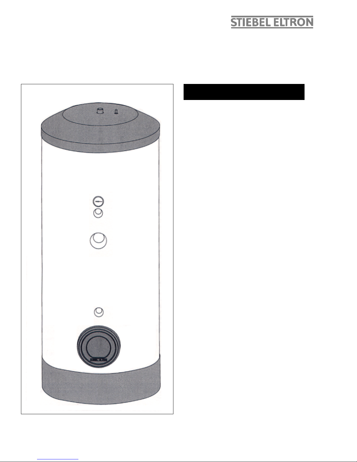
SBB 300 plus, SBB 400 plus, SBB 600 plus
Operation & Installation
Instruction Manual
1 Operation and Service
1.1 Start-Up
2 Maintenance and Cleaning
2.1 Pressure Relief Valve
2.2 Decalcification
2.3 Sacrificial Anode – Inspection /
Replacement
3 Failures – Cause – Correction
4 Technical Specifications
4.1 Technical Data
4.2 Dimensions
Installation Instructions
5 General
5.1 Description
5.2 Delivery Configuaration
5.3 Regulations and standards
5.4 Set-up and operation
6 Set-up and installation
6.1 Set-up
6.2 Connection
6.3 Heater Installation
6.4 Hot water Installation
6.5 Hot Water Temperature Probe
6.6 Solar Temperature Probe
6.7 Connection to the Solar Unit
6.8 Sacrificial Anode
Index
Page 2

Important Tip
Stiebel Eltron hot water heaters should only be installed or serviced by licensed installers.
These are not do-it-yourself appliances.
Please hand this Operation and Installation Manual and hand over to the home or building owner when the
installation is complete.
Operating Instructions for the User and the Technician
1. Operation and Service
1.1 Start-up
The boiler (1) and solar storage tank (11), constitute a functional unit (refer Diagram 4 and 5).
Hot water is generated throughout the year by the solar collectors.
The entire heater and hot water system must be filled with water and have adaquate air ventilation. Please, refer to the
solar collector’s and the boiler’s installation instructions.
2. Maintenance and Cleaning
Routine care and maintenance extends the life expectancy and operating safety of the hot water storage unit.
The outer casing should be cleaned with a slightly damp cloth and commercially available neutral cleaning agent, this
should be done on a regular basis
2.1 Temperature / Pressure Relief Valve
The proper function of the T & P relief valve is required to prevent damage to the hot water storage unit. The T & P valve
needs to be open during cold-water addition. The water has to flow from the relief line at full stream.
The discharging water can be hot!
2.2 Decalcification
With hard tap water, a deposit of scale will form on the inside of the storage unit. Based on professional experience, it is
necessary to decalcify with commercially available solvents at timely intervals. Follow the manufacturers instructions for
solvent use. The hot water storage unit needs to be emptied. The inspection cover must be removed and sediments on
the tank bottom must be flushed.
2.3 Replacement of the Sacrificial Anode
Depending on the composition of the tap water, an inspection of the sacrificial anode (Pos. 1, Diagram 1) timely intervals
is recommended. With heavy wear, an original equipment replacement anode must be installed to protect the inner
container from corrosion. An inspection should be performed at least once a year.
3. Failures – Causes – Correction
Failures
Causes
Correction
Inadequate water pressure
Shut-off valve is not completely open. Cold
or hot water line is obstructed.
Open Shut-off valve. Clean or exchange
pipes.
Hot water flow inadequate
Boiler temperature is set too low.
Recommended 176 to 185º F.
Heat exchanger is calcified.
Set boiler to recommended temperature.
Clean heat exchanger.
Hot water storage tank not
being heated
Program selection at the heater control is
not properly selected.
Select and set program per instructions.
Outlet quantity inadequate
Aerator at the extraction point blocked.
Unscrew aerator and clean.
Hot water supply too fast
exhausted
Flow rate too high. Recommended 2.6-3.9
gal./min.
Restrict Spigot valve rate.
Page 3
1
4. Technical Specifications
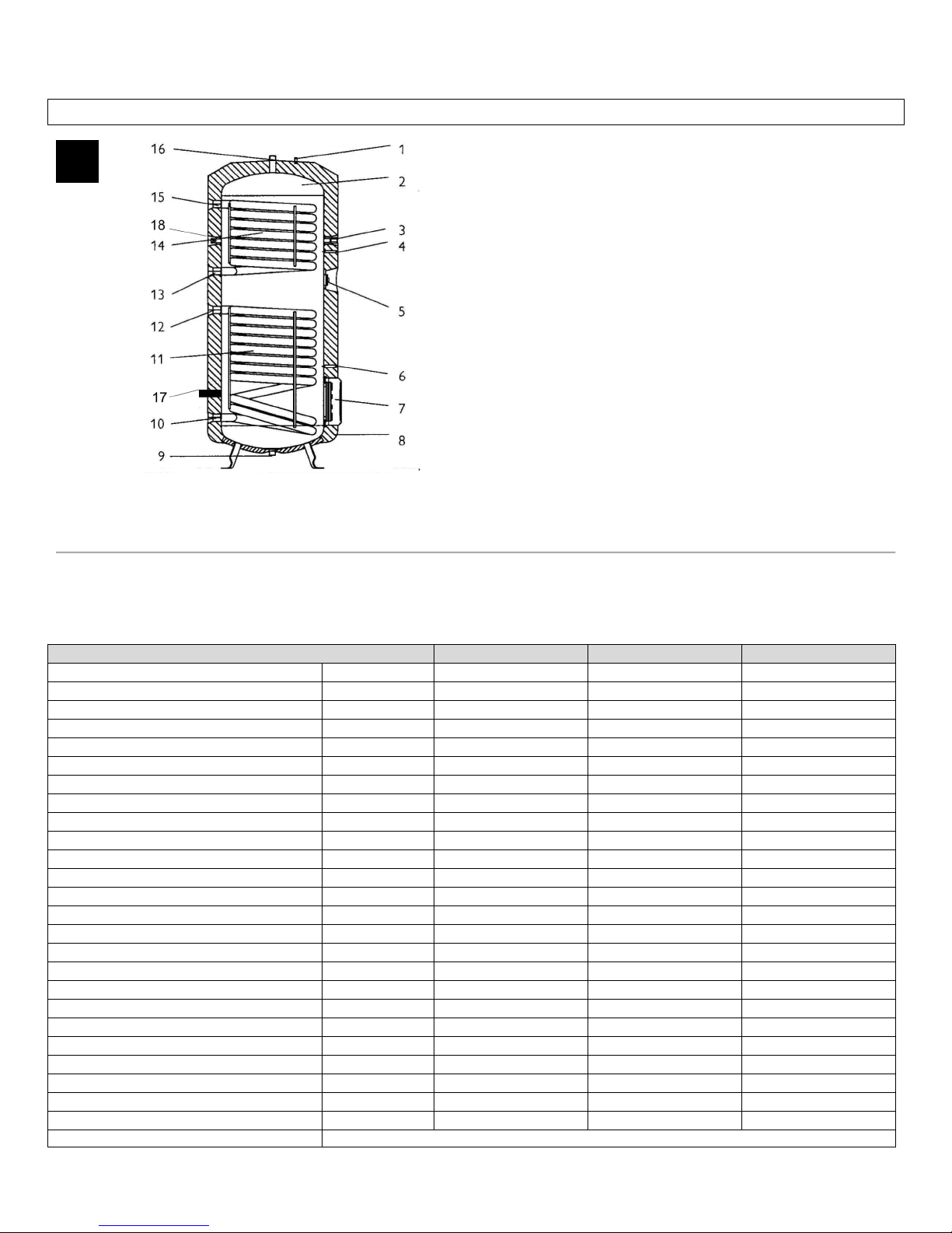
Components of the SBB…plus
1 Sacrificial anode indicator
2 Glass lined steel tank
3 Immersion sleeve for boiler temperature probez
4 Thermometer well
5 Spare port
6 Immersion sleeve for solar temperature probe
7 Inspection port
8 Expanded polystyrene-thermal insulation
9 Cold water inlet (SBB 300 & SBB 400)
10 Solar inlet
11 Solar heat exchanger
12 Solar return
13 Heat exchanger from boiler feed
14 Upper heat exchanger
15 Heater exchanger to boiler return
16 Warm water outlet / T & P relief valve location
17 Cold water inlet (SBB 600)
18 Circulation port
Diag. 1.
4.1 Technical Data
Type
SBB 300 plus
SBB 400 plus
SBB 600 plus
Contents
Storage capacity
Gal / ltr
80.6 / 305
108.6 / 411
162.9 / 617
Volume of heat exchanger, top
Gal / ltr
1.9 / 7.3
2.2 / 8.2
2.5 / 9.6
Volume of heat exchanger, bottom
Gal / ltr
2.7 / 10.1
2.9 / 11.3
3.5 / 13.2
Pressure
Working pressure
PSI / bar
150 / 10
150 / 10
150 / 10
Tested to pressure
PSI / bar
217 / (15)
217 / (15)
217 / (15)
Max. pressure of boiler loop
PSI / bar
150 / 10
150 / 10
150 /10
Temperature
Max. temperature solar loop
°F / °C
203 / 95
203 / 95
203 / 95
Max temperature boiler loop
°F / °C
203 / 95
203 / 95
203 / 95
Heat exchanger
Surface area heat exchanger top
sq. in. /m2
1705 / 1.1
2015 / 1.3
2325 / 1.5
Surface area heat exchanger bottom
sq. in. /m2
2325 / 1.5
2635 / 1.7
3100 / 2.0
Weights
Tank weight empty
lb. / kg
339 / 154
412 / 187
544 / 247
Tank weight full
lb. / kg
1,051 / 477
1,362 / 618
1,955 / 887
Other
Standby losses in 24 hours
KWh / BTU
1.9 / 6500
2.2 / 7500
2.9 / 10,000
Cold/hot water connection
for 1” copper pipe w/adapters, provided w/ unit
Page 4
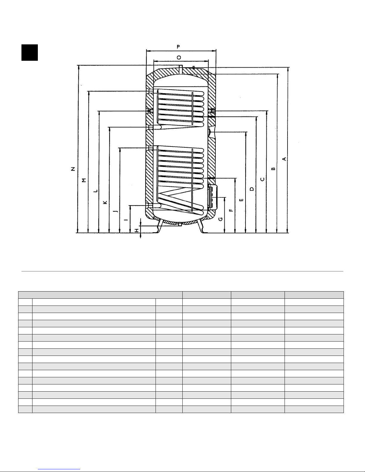
Dimensions
Diag. 2.
4.2 Dimensions
Type
SBB 300 plus
SBB 400 plus
SBB 600 plus
A
Height of unit w/insulation
in./mm
66.1/1679
72.7/1848
68.3/1735
B
Height of unit without insulation
in./mm
63.3/1609
70.1/1781
65.7/1670
C
Height of well for temp. sensor
in./mm
46.4/1179
48.7/1238
46.9/1192
D
Height thermometer
in./mm
41.1/1045
43.0/1093
41.5/1055
E
Height spare port
in./mm
40.3/1025
42.4/1078
40.9/1040
F
Height of well for temp. sensor
in./mm
21.9/557
22.0/560
23.4/595
G
Height inspection flange
in./mm
14.4/365
14.4/367
15.9/405
H
Height cold water feed
in./mm
2.9/73
2.6/65
2.0/50
I
Height solar cold feed
in./mm
11.0/280
11.1/282
10.9/277
J
Height solar hot return
in./mm
34.0/865
34.1/867
33.9/862
K
Height heater hot boiler return
in./mm
38.4/975
44.5/1130
42.9/1089
L
Height circulation port
in./mm
52.7/1339
63.0/1600
57.2/1453
M
Height cold boiler feed
in./mm
52.7/1339
63.0/1600
57.2/1453
N
Overall height
in./mm
67.08/1704
73.74/1873
69.29/1760
O
Width without thermal insulation
in./mm
21.65550
23.62/600
29.52/750
P
Width with thermal insulation
In./mm
27.55/700
29.52/750
36.22/920
2
Page 5
Installation instructions for the Installer
5. General
Diagram 1 is referenced for explanation of the following text.
5.1 Brief Description of the Appliance
5.1.1 Application
The Stiebel Eltron Vertical Solar Storage tank SBB … Plus, in combination with Stiebel Eltron’s Solar Collector is an
economical hot water generator.
5.1.2 Connections
All connections (cold and hot) are readily accessible and allow for easy installation.
5.2 Delivery Configuration
The hot water storage tank SBB … Plus is wrapped in plastic and is delivered on a one-way pallet. The storage tank has
foam insulation, a ABS outer casing and ABS cover.
Equipment
• Storage unit with two welded steel plain-ended pipe heat exchangers
• Hot water corrosion protection with special enamel coating
• Maximum operation pressure
Hot water 150 PSI
Heated water 150 PSI
• Three immersion sleeves for housing of temperature probe and thermometer
• Magnesium Safety Anode
• Circulation Socket
• Attached Flange inspection cover (SBB models)
• PU Foam insulation 2.95 in. (70 mm.) thick
• ABS outer casing with zipper in protective pouch
• ABS Cover and Flange cover
Only for 600:
• Removable polyurethane-side panels with fastening strap and locking parts
5.3 Tasks to be performed by Installer
An approved technician should perform the setup, installation and initial start-up following these instructions.
5.4 Regulations and Standards
Refer to: Local Construction regulations, fire-code and trade control regulations.
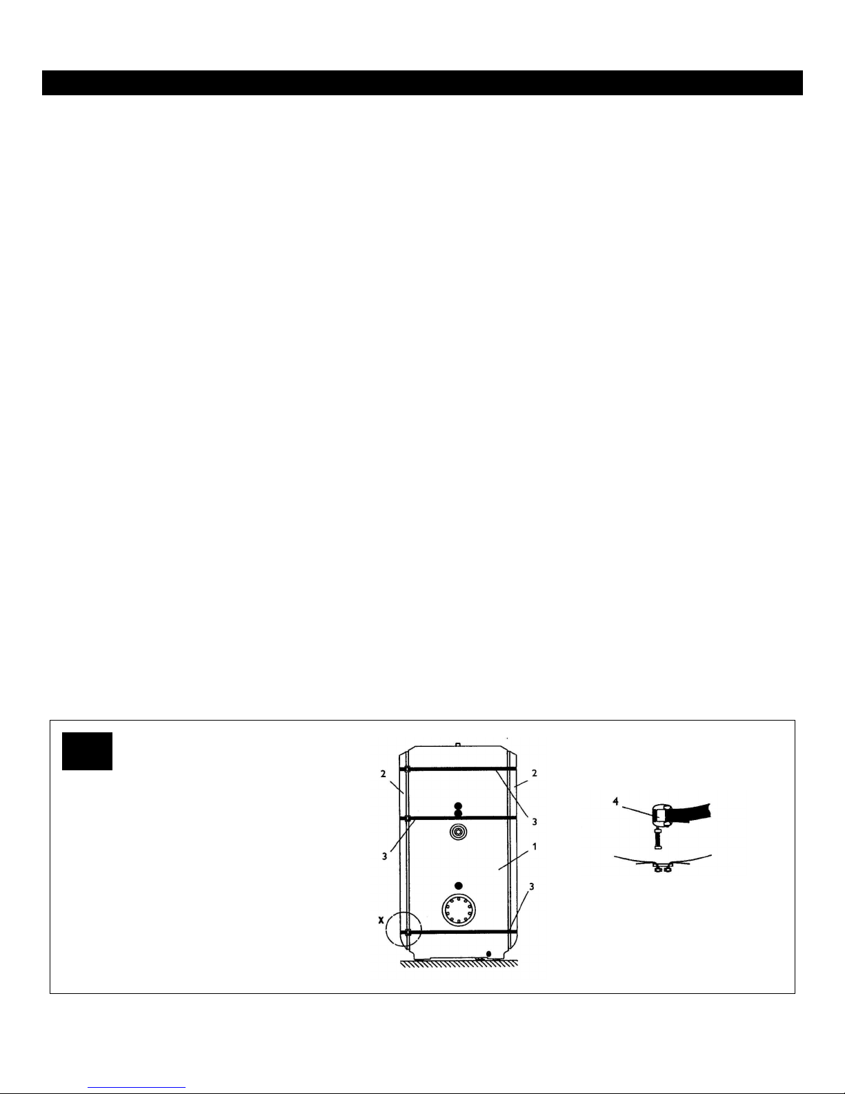
Solar Tank SBB 600 plus
with insulation
1 Solar tank
2 PU side panel
3 Fastening strap
4 Locking part
3
Page 6

6. Set-up and Installation
6.1 Set-up
Inspect the packaging for damage and remove packaging at the installation site. Verify presence of six brass thread to
sweat fittings.
The installation site must be structurally capable of supporting the weight of the tank when filled. The location has to be
above freezing. The water drainage pipe must be freeze proof.
6.2 Connection
Refer to Diagram1 and Diagram 2.
6.3 Heater Installation
The installation of the hydronic loop is shown in Diagram 4. The circuit must include a Temperature / Pressure Relief
Valve, and air-vent, a check valve, and an expansion tank.
6.4 Hot Water Installation
6.4.1 Prior to installation check that the local conditions are compatible with the appliance design, especially that the
maximum working excess pressure of 150 PSI (10 bar.) is not exceeded.
6.4.2 A steel or a copper pipe with insulation can be used for the hot water connectors. Copper pipe with insulation is
especially suitable due to its low heat loss.
Required combination
Cold water pipeline Hot water pipeline
Copper pipe copper pipe
Steel pipe steel or copper pipe
Plastic steel or copper pipe
6.4.3 All safety components must be installed into the cold water supply (7,8,9 & 14 Diagram 4). The order of the
individual fittings must be in accordance to local regulations.
6.4.4 The pressure regulator has to be set to 150 PSI (10 bar). It can only be installed into the cold water supply. The
supply has to be thoroughly inspected prior to installation. Installation of dirt filters or any other narrowing of the supply
line to the pressure relief valve is forbidden.
The pressure relief valve (13) has to be easily accessible. Expansion water generated during the heating has to flow
visibly to a drain.
The drainage pipe must be large enough to accommodate water drainage with a fully opened T & P valve. The drainage
pipe must be protected from freezing and must not lead outdoors.
The pressure regulator (14) has to be set so no water drips from the T & P valve.
Heavy dripping of the T & P valve can be caused by dirt in the valve seat or water pressure. Water pressure needs to re
regulated below 150 PSI.
6.4.5 Prior to filling all screws must be tight.
6.4.6 Drainage of the hot water tank is via the drain valve (7).
6.4.7 A re-circulator can be attached to a separate socket across the thermometer. Drill the outer casing with a hole saw
∅ 50 where marked and remove insulation from the socket in that area.
For energy conservation, use of a circulator is not recommended.
Page 7
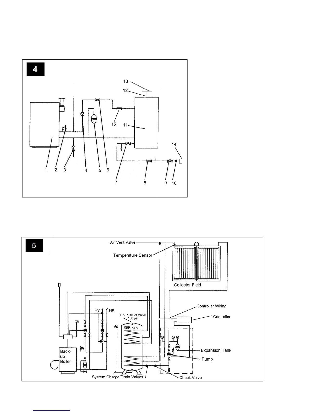
Installation Diagram Solar storage tank SBB plus to Hydronic back-up
Diag. 4
System Diagram
1 Boiler
2 T & P valve
3 Boiler filler and drainage faucet
4 Heating loop circulator
5 Pressure expansion tank
6 Check valve
7 Drainage faucet for the tank
8 Check valve
9 Shut-off valve
10 Cold water pipe
11 SBB plus storage tank
12 Hot water pipe
13 T & P valve
14 Pressure regulator
15 Air-vent
Page 8
6.5 Hot water temperature probe
6.5.1 The hot water temperature probe is to be installed into the upper immersions sleeve (Pos. 3 Diagram1).
6.6 Solar Storage Tank – Temperature Probe
The solar storage tank temperature probe to lower immersion sleeve of the hot water storage tank (Pos. 6 Diagram 1).
The temperature probe must be completely inserted into the probe sleeve.
6.7 Connection to the Solar Unit
The installation of the solar loop is shown in Diagram 5. The solar loop must include temp/pressure relief, an air-vent, a
check valve and an expansion tank. Refer to the separate operation and installation instructions for the solar collector
SOL 25 plus.
Test operation after installation. Start up must follow the approval of the installer (refer operation and use).
6.8 Sacrificial anode (spare part)
If a sacrificial anode is installed into the SBB … plus storage tank, the following must be observed:
Installation – sacrificial anode
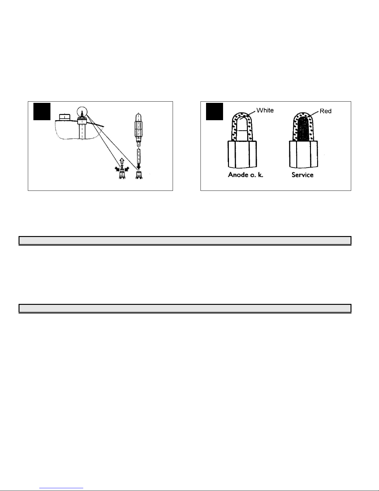
• Pull out the red shut-off plug while simultaneously depressing the pressure ring, Diagram 6.
• Push in the open pipe end of the indicator element until dead-stop.
• Attach the sticker “Note Signal Anode” to a highly visible spot on the insulation.
When the storage tank is not operated with a signal display, the red plug must remain in the anode!
Function – Sacrificial indicator
• After consumption of the anode, humidity escapes through the hollow anode core to the signal cartridge and causes a
color change there (refer Diagram 7)
• When the cartridge turns red contact the installer so he can check the anode and if needed replace it.
Routine maintenance improves operating safety and life expectancy of the solar hot water
storage tank SBB … plus.
6
7
Page 9

STORAGE TANK FOR SOLAR APPLICATIONS WARRANTY
Stiebel Eltron warrants to the original owner that the SBB….plus; Storage tank for solar hot
water systems will be free from defects in workmanship and materials for a period of five
(5) years from the date of purchase.
Should the part(s) prove to be defective under normal use during this period, Stiebel
Eltron, Inc. will be responsible for replacement of the defective part(s) only. Stiebel Eltron,
Inc. will not be liable for any costs of transportation, removal, reinstallation, or any other
labor or freight charges that may arise in connection with a warranty claim or any incidental
or consequential expenses.
This warranty does not apply:
1. to conditions resulting from a failed component or part that is not part of the solar
storage tank
2. to freeze damage
3. to conditions resulting from misuse, abuse, neglect, accident, or alteration
4. to conditions resulting from the introduction of harmful chemicals, caustic fluids, or
liquids deleterious to copper tubing, including improperly applied or maintained heat
transfer fluids
5. to excessive pressure
6. to conditions resulting from floods, earthquakes, winds, fire, lightning, or
circumstances beyond the manufacturer's control
7. to installation methods which do not conform to relevant national, state or local
codes and ordinances, good industry practices or applicable manuals, diagrams,
technical bulletins or written installation instructions; and, to applications other than
medium temperature.
To obtain service under this warranty, the owner must first secure written authorization
from Stiebel Eltron, Inc. The owner shall be required to show proof of purchase date, and
to pay all transportation costs to return the defective part(s) for repair or replacement.
STIEBEL ELTRON, INC.
17 West Street
West Hatfield, MA 01088
Phone: 800-582-8423 413-247-3380
Fax: 413-247-3369
E-Mail: [email protected]
www.stiebel-eltron-usa.com
 Loading...