

Page 1
OPERATION AND INSTALLATION
FUNCIONAMIENTO E INSTALACIÓN
MODE D’EMPLOI ET INSTALLATION
.ĉ®êļ¼ŒùźÐļ¼®ŷ|Œ¼ļä¼|Œ¼ļŷêŒä¼ù¼Œļê|÷şĤä¼|ŒêĉÖ¼ù¼ă¼ĉŒ
|ù¼ĉŒ|®Ēļ®¼|Öş||Ïş¼ÖĒêĉ®êļ¼ŒĒĒĉ|ù¼ĉŒ|®Ēļ¼ù½ŒļêĒ®¼ļ¼Ïş¼ļſĒ
ä|şÏϼé¼|şä|şÏÏ|Ö¼êĉ®êļ¼Œ|Ŷ¼½ù½ă¼ĉŒ®¼ä|şÏÏ|Ö¼½ù¼Œļêış¼|şŹêùê|êļ¼
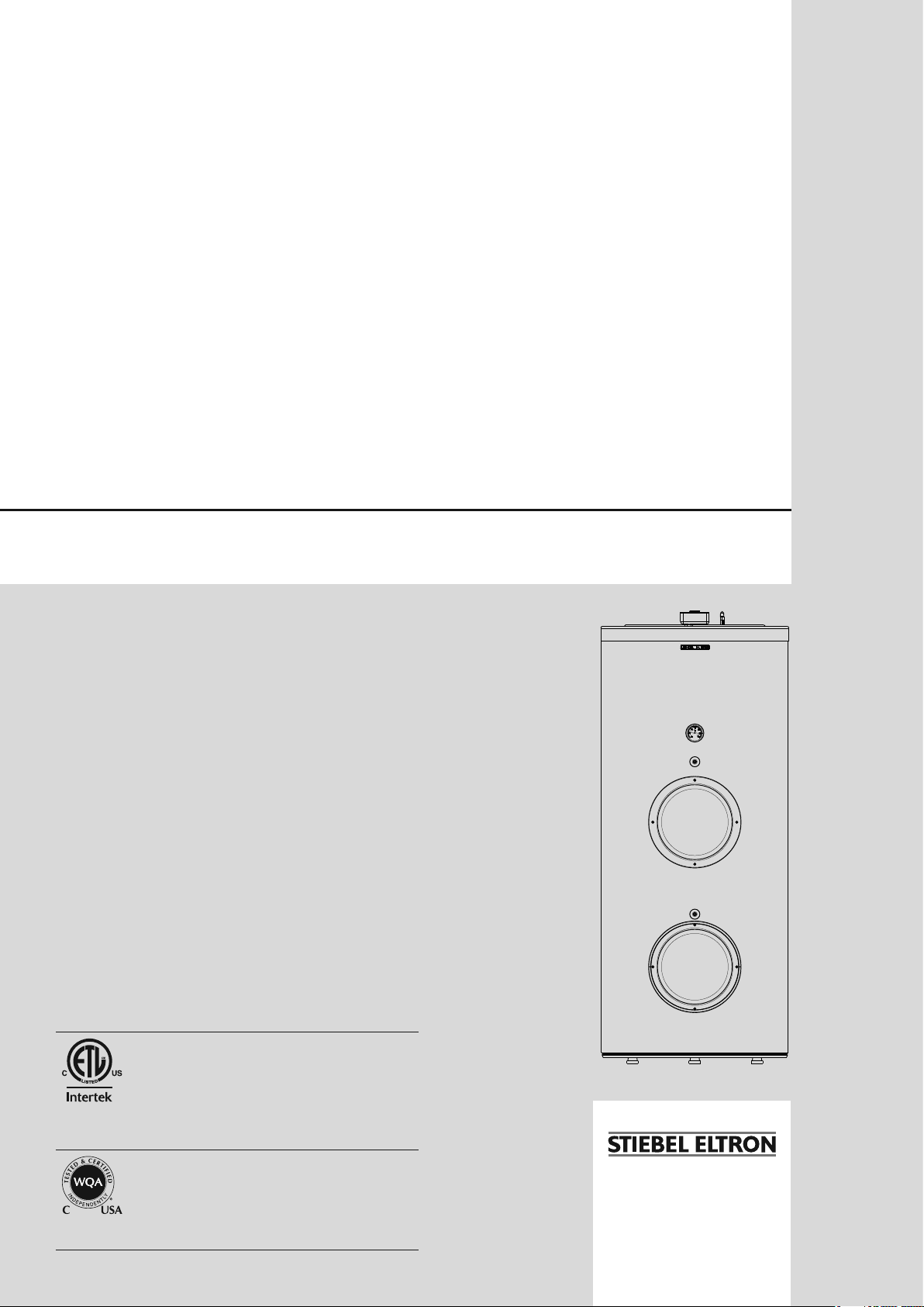
» SB 300 E
» SB 400 E
Conforms to ANSI/UL Std. 174
Certified to CAN/CSA Std. C22.2 No. 110-94
Conforme a ANSI/UL Std. 174
Certificación con CAN/CSA Std. C22.2 No. 110-94
Conforme à la norme ANSI/UL Std. 174
Certifié à la norme CAN/CSA Std. C22.2 No. 110-94
Tested and certified by WQA to NSF/ANSI372
for lead free compliance.
Probado y certificado por WQA NSF/ANSI 372 para
el cumplimiento de las regulaciones sin plomo.
Testé et certifié par WQA à la NSF/ANSI 372 pour
une utilisation sans plomb.
Page 2

CONTENTS
SPECIAL INFORMATION
OPERATION
1. General information ____________________________________3
2. Safety _____________________________________________________3
2.1 Intended use _________________________________________________3
2.2 Incorrect use _________________________________________________ 3
2.3 General safety instructions _______________________________3
2.4 Heat exchanger loop _______________________________________ 3
2.5 Test symbols _________________________________________________3
3. Register your product __________________________________4
4. Appliance description __________________________________4
4.1 Heating the DHW tank _____________________________________4
5. Using the electric heating element ____________________4
6. Maintenance and care __________________________________4
6.1 Temperature / pressure relief valve _____________________5
6.2 Decalcification _______________________________________________ 5
6.3 Replacement of the sacrificial anode ___________________ 5
7. Plumbing troubleshooting _____________________________5
7.1 Notifying a qualified contractor _________________________5
7.2 Safety label __________________________________________________6
8. Safety _____________________________________________________6
8.1 General safety instructions _______________________________6
8.2 Instructions, standards and regulations _______________6
9. Preparations _____________________________________________6
9.1 Transport _____________________________________________________6
9.2 Storage ________________________________________________________ 7
9.3 Delivery configuration _____________________________________7
9.4 Installation site ______________________________________________7
9.5 Siting the appliance ________________________________________7
10. Installation _______________________________________________8
10.1 Water connection ___________________________________________8
10.2 Heating connection _________________________________________9
10.3 Power supply ________________________________________________ 9
11. Commissioning ________________________________________ 10
11.1 Commissioning ____________________________________________ 10
11.2 Recommissioning _________________________________________ 10
12. Shutting down _________________________________________ 10
13. Electrical Troubleshooting ___________________________ 10
13.1 Resetting the high limit safety cut-out _______________ 11
14. Maintenance and cleaning ___________________________ 11
14.1 Removing the heating element cover _________________ 11
14.2 Draining the tank _________________________________________ 11
14.3 Descaling the electric element _________________________ 11
14.4 Valves _______________________________________________________ 11
14.5 Replacing the electric element cover _________________ 11
15. Specifications __________________________________________ 12
15.1 Dimensions _________________________________________________ 12
15.2 Features ____________________________________________________ 13
15.3 Data table ___________________________________________________14
15.4 Spare parts_________________________________________________ 15
15.5 Spare parts list ____________________________________________ 15
15.6 Wiring diagram _________________________________________________ 16
16. Environment and Recycling _______________________________ 16
17. Warranty ____________________________________________________ 17
SPECIAL INFORMATION
- Observe all applicable national and regional regulations and instructions during installation.
- The appliance is not approved for outdoor
installation.
- If the appliance is permanently connected to the
power supply, ensure that the appliance can be
separated from the power supply by an isolator
that disconnects all poles with at least 1/8˝/4 mm
contact gap. Contactors, disconnect switches or
circuit breakers can be used for this.
- Observe the safety regulation to prevent contact
with dangerous ‘live’ currents.
- The appliance is pressurized. During the heat-up
process, expansion water will drip from the safety
valve.
- Regularly activate the safety valve to prevent
it from becoming blocked, e.g. by limescale
deposits.
- Install a type-tested safety valve in the cold water
supply line.
- The maximum pressure in the cold water supply
line must be at least 20% below the response
pressure the safety valve. If the maximum pressure in the cold water supply line is higher, install
a pressure reducing valve.
- Size the drain so that water can drain off unimpeded when the safety valve is fully opened.
- Fit the discharge pipe of the safety valve with a
constant downward slope and in a room without
risk of frost.
- The safety valve discharge aperture must remain
open to atmosphere.
- Never set the heat exchanger loop pressure
greater than the potable (domestic) water supply
pressure. If potable water pressure is too low, a
booster pump may be needed to assure that it exceeds the required heat exchanger loop pressure.
2 |SB 300-400 E www.stiebel-eltron-usa.com
Page 3
OPERATION
General information
OPERATION
1. General information
The chapters “Special information” and "Operation" are intended
for appliance users and qualified contractors.
The chapter "Installation" is intended for qualified contractors.
Note
Read these instructions carefully before using the appliance and retain them for future reference.
Pass on the instructions to a new user if required.
2. Safety
2.1 Intended use
The appliance is intended for DHW heating within the application
limits. See 15.3, “Data table”, pg. 14.
The appliance is intended for domestic use, i.e. it can be used
safely by untrained persons. The appliance can also be used in a
non-domestic environment, e.g. in a small business, as long as it
is used in the same way.
Any other use beyond that described shall be deemed inappropriate. Observation of these instructions and of instructions for any
accessories used is also part of the correct use of this appliance.
WARNING Scalding
The water in the DHW tank can be heated to temperatures in excess of 149 °F (65 °C). T here is a risk of scalding
at outlet temperatures in excess of 110 °F (43 °C).
f Ensure you do not come into contact with the water
when discharged.
WARNING Burns
Touching hot components can lead to burns.
When working on hot components, always wear protective working clothing and safety gloves.
The pipework connected to the DHW outlet of the appliance can reach temperatures in excess of 149 °F (65 °C).
CAUTION
!
Install temperature and pressure protective equipment
required by local codes and no less than a combination temperature and pressure relief valve certified by a
nationally recognized testing laboratory that maintains
periodic inspection of production of listed equipment or
materials, as meeting the requirements for Relief Valves
and Automatic Gas Shutoff Devices for Hot Water Supply
Systems, ANSI Z21.22. T his value must be marked with a
maximum set pressure not to exceed the marked maximum working pressure of the water heater. Install the
valve into an opening provided and marked for this purpose in the water heater, and orient it or provide tubing
so that any discharge from the valve exits only within 6
inches above, or at any distance below, the structural
floor, and does not contact any live electrical part.
ENGLISH
2.2 Incorrect use
The following are not permitted:
- Heating liquids other than potable water
- Operating the appliance with an empty DHW tank
- Operating the appliance outside the application limits (See
15.3, “Data table”, pg. 14)
- Interrupting the power supply
2.3 General safety instructions
Only qualified contractors should carry out the electrical work and
installation of this appliance. Qualified contractors are responsible
for adherence to all applicable regulations.
Operate the appliance only when fully installed and with all safety
equipment fitted.
WARNING
Contact with live components presents a threat to life.
Damage to the electric insulation or to individual components may result in a threat to life.
f If there is damage to the insulation, disconnect the
power supply and arrange a repair.
All work on the electrical installation must be carried
out by a qualified contractor.
Caution
!
Only operate the appliance when the DHW tank has been
filled.
Caution
!
Keep the appliance installation room free from air contaminated with oil or salt and corrosive or explosive substances.
2.4 Heat exchanger loop
The SB E tanks have an indirectly fired heat exchanger loop. This
may be used in a variety of scenarios which include boiler loops,
geothermal systems, radiant floor loops, etc. Since the interior
of the heat exchanger is uncoated carbon steel, they must be
configured in a closed loop.
Use only a mixture of inhibited propylene glycol and de-ionized
water. The percentage of the glycol in the mixture depends upon
the climate. Some areas require that the propylene glycol be
GRAS, which is a food grade liquid (Heat exchanger type SW,
AWWA Fluid Class II - see MSDS for handling instructions).
2.5 Test symbols
See 7.1.1, “Sample type plate”, pg. 5.
www.stiebel-eltron-usa.com SB 300-400 E | 3
Page 4

OPERATION
Register your product
3. Register your product
NOTE:
You must register this product within 90 days of purchase on our web site in order to activate any standard
warranty or to be eligible for the extended warranty.
Go to our website at: www.stiebel-eltron-usa.com and
click on “Register Your Product.”
Before beginning the registration process, we suggest that you
gather the necessary information as follows:
Model, Example: SB 300 E (from the label that is on the side of
the unit)
Number listed after “Nr.”
Place of Purchase
Purchase Date
First & Last Name
Email address
Physical Address
Phone Number
If you have any questions concerning the registration process or
warranty options, please contact Stiebel Eltron USA directly at
800.582.8423.
If either of the last two heating methods require a temperature
sensor, 2 ports are provided on the opposite side of the tank from
the auxiliary and heat exchanger connections.
5. Using the electric heating element
A 3 kW electric heating element comes standard with this product.
The element has a built-in temperature probe that detects the tank
water temperature.
The appliance’s 3 kW electric resistance heating element is factory
preset at 125 °F (52 °C). The setpoint of the heating element can
be changed easily. A knob is located under the heating element
and can change the level of comfort to meet the needs of the user.
The heating element can be either unplugged during a period of
disuse or removed entirely.
For convenience, the heating element can be removed from the
tank without draining it.
Thermostat knob
Setpoint notch
4. Appliance description
The appliance is designed for indoor installation. The appliance
is equipped to heat water through a number of different heating
methods.
There are three ways that this unit can heat water:
- 3 kW electric resistance heating element
- Indirect heat via internal coil heat exchanger
- Indirect heat via auxiliary inlet/outlet ports
The entire heater and hot water system must be filled with water
and have adequate air ventilation. If used, please refer to the solar
collectors and the boilers installation instructions.
4.1 Heating the DHW tank
The first method of heating is by the 3 kW electric resistance heating element. This is the appliances most basic mode of operation.
An integral temperature sensor detects the thermal energy content
of the amount of heat in the DHW tank. The water in the DHW
tank is heated if the amount of heat is lower than that required to
achieve the set temperature.
The second method of heating is by the internal coil heat exchanger. This heat exchanger is designed to have a heat transfer
fluid circulate through it from an indirect heater. This indirect
heater can be a closed loop solar thermal system, boiler or other
traditional appliance that generates heat and transfers it through
a corrosion inhibited heat transfer fluid.
The third method of heating is by auxiliary ports located on the
side of the unit. These auxiliary ports offer direct access to the
domestic water in the tank. A flat plate heat exchanger should be
used to exchange heat between an indirect heater and the water
in the tank.
6. Maintenance and care
Routine care and maintenance extends the life expectancy and
operating safety of the hot water storage unit. The outer casing
should be cleaned with a slightly damp cloth and commercially
available neutral cleaning agent. This should be done on a regular
basis.
WARNING
Never spray the appliance with water.
Never spray water into the appliance.
WARNING Injury
!
Maintenance work, such as checking the electrical safety, must only be carried out by a qualified contractor.
4 |SB 300-400 E www.stiebel-eltron-usa.com
Page 5
OPERATION
Plumbing troubleshooting
Appliance compo-
Care and maintenance tips
nents
Casing Use a damp cloth to clean the casing sections. Never
use abrasive or corrosive cleaning agents.
DHW tank
The DHW tank is equipped with a sacrificial anode
and wear indicator to safeguard it against corrosion.
The wear indicator should be checked regularly. Otherwise there is a risk of corrosion.
Electric resistance
heater
Check the condition of the electric resistance heater.
This will extend the expected life of the element.
6.1 Temperature / pressure relief valve
WARNING: The T&P relief valve is designed to relieve
!
built up pressure in the water heater. Fluid may be
discharged at high temperature and/or pressure. Scalding hot
water injuries can occur.
The proper function of the Temperature / Pressure (T&P) relief
valve is required to prevent damage to the hot water storage unit.
The T&P valve needs to be open during cold-water filling of the
unit. When water flows from the relief line at full stream, the tank
is filled, and the T&P valve can be returned to its normal position.
6.2 Decalcification
With hard tap water, a deposit of scale will form on the inside of
the storage unit. Based on professional experience, it is necessary
to decalcify with commercially available solvents at timely intervals. Follow the manufacturers instructions for solvent use. The
hot water storage unit needs to be emptied to do this process. The
clean-out port cover must be removed and sediments on the tank
bottom must be flushed.
6.3 Replacement of the sacrificial anode
Depending on the composition of the tap water, an inspection of
the sacrificial anode at timely intervals is recommended. With
heavy wear, an original equipment replacement anode must be
installed to protect the inner container from corrosion. An inspection should be performed at least once per year.
7. Plumbing troubleshooting
Problem Cause Remedy
Inadequate
water pressure
Hot water flow
inadequate
Hot water
storage tank not
being heated
Faucet flow rate
inadequate
Hot water supply exhausted
too quickly
7.1
If you cannot remedy a failure, notify your qualified contractor. To
facilitate and speed up your request, provide the serial number
from the type plate (000000-0000-00000). The type plate can be
found on the left, above the "DHW outlet" connection.
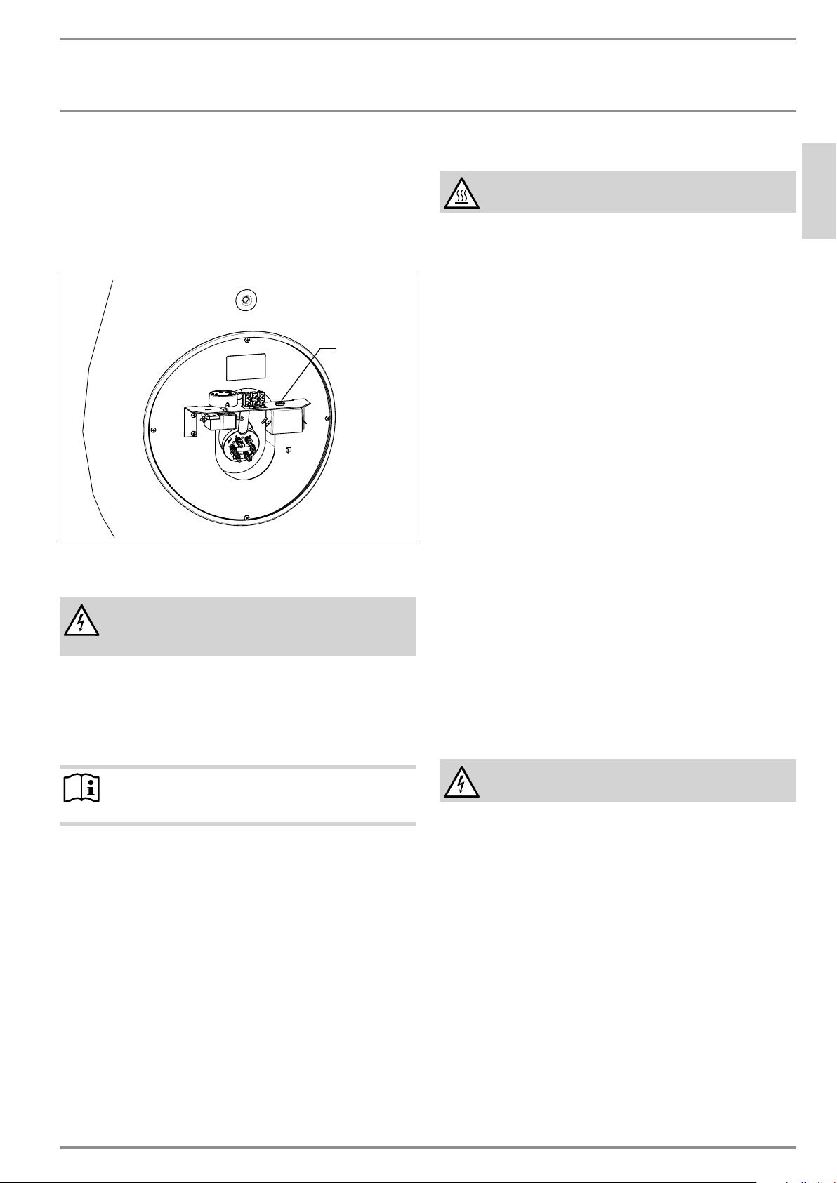
7.1.1 Sample type plate
Shut-off valve is not completely open.
OR
Cold or hot water line is ob-
Open shut-off valve. Clean or
replace pipes.
structed.
Indirect boiler setpoint tem-
perature is too low.
Recommended 176–185 °F
(80–85 °C).
OR
Heat exchanger is calcified.
Program selection at the
heater control is not properly
Set boiler to recommended
temperature
OR
Clean heat exchanger.
Select and set program per
instructions.
selected.
Aerator at the extraction
Unscrew aerator and clean.
point is blocked.
Flow rate is too high. Rec-
ommended 2.6–3.9 gpm
Restrict spigot valve rate.
(9.8–14.7 l/min).
Notifying a qualified contractor
Made in EU
Hecho en EU
Fabriqué en EU
SB 300 E
M-NO.: 234110
S-NO.:
Technical data
Datos técnicos
Données techniques
Volume:
Volumen:
Volume:
293 l / 77.4 gal
Supply:
Alimentación:
Alimentation:
220-240 V AC, 60 Hz
SINGLE PHASE L-L ONLY
Power:
Potencia:
Puissance:
3 kW / 10,239 BTU/h
Max. pressure:
Presión máxima:
Pression max:
1 MPa / 145 PSI
Testing pressure:
Presión de prueba:
Pression d'essai:
1.5 MPa / 217 PSI
Standby loss:
Pérdida de calor:
Pertes en mode de veille:
2.8 kWh/24h
Heat exchanger
Intercambiador de calor
Échangeur de chaleur
Max. pressure:
Presión máxima:
Pression max.:
1 MPa / 145 PSI
Heating surface:
Superficie de calefacción:
Surface de chauffe:
2
1.5 m
Volume:
Volumen:
Volume:
Max. temp.:
Temperatura máxima:
Temp. max.:
/ 16.1 ft
9.5 l / 2.37 gal
95 °C / 203 °F
4010487
Conforms to UL STD. 174
Certified to CAN/CSA STD. C22.2 No.110-94
2
315277-38053
ENGLISH
www.stiebel-eltron-usa.com SB 300-400 E | 5
Page 6
INSTALLATION
Safety
M-NO.: 234111
S-NO.:
Technical data
Datos técnicos
Données techniques
Volume:
Volumen:
Volume:
413 l / 109.1 gal
Supply:
Alimentación:
Alimentation:
220-240 V AC, 60 Hz
SINGLE PHASE L-L ONLY
Power:
Potencia:
Puissance:
3 kW / 10,239 BTU/h
Max. pressure:
Presión máxima:
Pression max:
1 MPa / 145 PSI
Testing pressure:
Presión de prueba:
Pression d'essai:
1.5 MPa / 217 PSI
Standby loss:
Pérdida de calor:
Pertes en mode de veille:
3.0 kWh/24h
SB 400 E
Made in EU
Hecho en EU
Fabriqué en EU
Heat exchanger
Intercambiador de calor
Échangeur de chaleur
Max. pressure:
Presión máxima:
Pression max.:
1 MPa / 145 PSI
Heating surface:
Superficie de calefacción:
Surface de chauffe:
Volume:
Volumen:
Volume:
Max. temp.:
Temperatura máxima:
Temp. max.:
Conforms to UL STD. 174
Certified to CAN/CSA STD. C22.2 No.110-94
2
1.92 m
/ 20.6 ft
11.1 l / 2.9 gal
95 °C / 203 °F
4010487
2
315298-38054
INSTALLATION
8. Safety
Only a qualified contractor should carry out the installation, commissioning, maintenance and repair of the appliance.
8.1 General safety instructions
To prevent the necessity of a warranty claim, use only original accessories and spare parts. If you need spare parts, call
800.582.8423.
8.2 Instructions, standards and regulations
Note
Observe all applicable national and regional regulations
and instructions.
Take note of the appliance type plate and See 15, “Specifications”,
pg. 12.
7.2 Safety label
CAUTION
To reduce the risk of electric shock or fire use only on a utility supply
having a maximum 250 volt, three wire system.
CAUTION
Risk of Electric Shock. Connect branch circuit equipment grounding
means to water heater. For detailed information, refer to instructions.
CAUTION
Risk of Electric Shock and Fire Hazard. Do not connect to supply
by extension cord.
FOR INSTALLED RATING SEE ELEMENT MARKING
Install temperature and pressure protective equipment required by
local codes, but not less than a combination temperature and
pressure relief valve certified as meeting the requirements for Relief
Valves and Automatic Gas Shutoff Devices for Hot Water Supply
Systems, ANSI Z21.22, by a nationally recognized testing laboratory
that maintains periodic inspection of production of listed equipment
or materials. The valve must be oriented, provided with tubing, or
otherwise installed so that discharge can exit only within 6 inches
(15 cm) above, or at any distance below, the structural floor, and
cannot contact any live electrical part.
CAUTION
If the water heater is retrofitted with supplemental heating
equipment, you must adjust both the thermostat controlling the
supplemental heat source (located in the water piping) and the
thermostat on the water heater (behind the access panel) to the
same temperature. Failure to adjust both thermostats to the same
temperature can cause loss of proper temperature control.
When a supplemental heat source is connected to the
appliance, a provision must be made to limit the heat
source temperature not to exceed that of the water heater
thermostat setting.
9. Preparations
9.1 Transport
CAUTION Injury
!
f Take note of the weight of the appliance.
f Use suitable transport aids (e.g. a hand truck) and
enough personnel for transportation.
Caution
!
The appliance is top heavy.
f Make sure the unit is not tilted.
f Only set the appliance down on an even base.
Do not unpack the appliance until it has arrived in the final installation room.
Leave the appliance in its packaging and on the pallet. This enables
horizontal transport and provides places to rest during transport.
Vehicular transport
Caution
!
The appliance must generally be stored and transported
vertically.
f Observe the information on the packaging.
Safety label on the appliance
6 |SB 300-400 E www.stiebel-eltron-usa.com
Page 7
INSTALLATION
Preparations
1
1 Recessed grips
Transport from vehicle to installation room
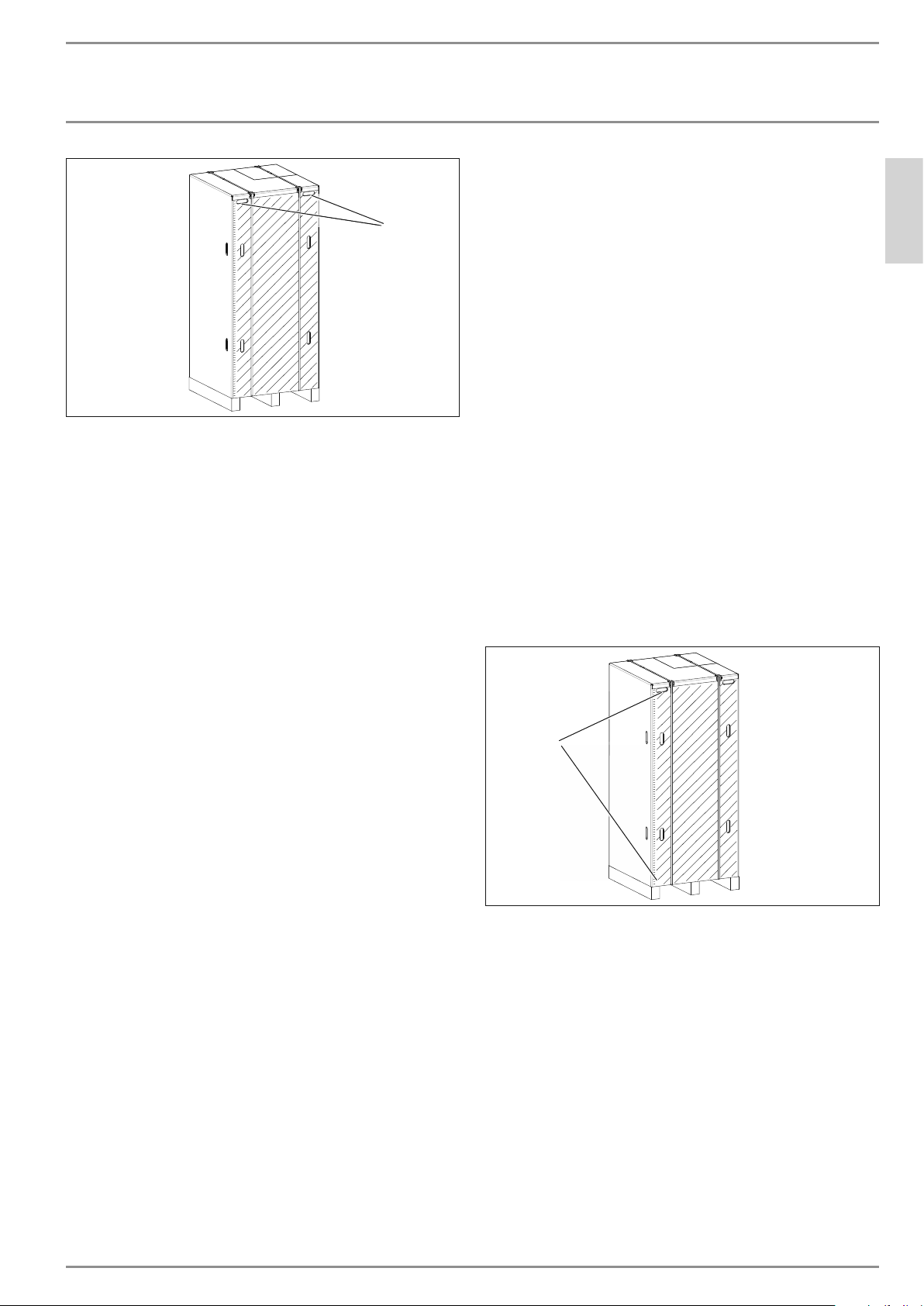
The cardboard box has reinforced recessed grips along the top of
the appliance. You can use these recessed grips, as well as the
pallet at the lower end, to carry the appliance into the installation
room. Take note of the weight of the appliance and ensure a sufficient number of personnel is available for handling the appliance.
9.2 Storage
If it is necessary to store the appliance for a prolonged period
before installation, observe the following information:
- Only store the appliance in a vertical position. Never store
the appliance horizontally.
- Store the appliance in a location that is dry and largely
dust-free.
- Protect the appliance from coming into contact with corrosive
substances.
- The floor of the installation room must be level and have sufficient load bearing capacity. Take note of the weight of the
appliance with a full DHW tank (See 15.3, “Data table”, pg.
14). A floor with insufficient weight capacity is in danger of
collapse. If the appliance is not evenly balanced, there may
be a risk of appliance damage.
- Always leave sufficient distance to provide access for installation, maintenance and cleaning. Observe the required minimum clearances (See 9.5, “Siting the appliance”, pg. 7).
- Ensure that the operation of other equipment in the installation room is not impaired.
- To reduce the required plumbed tube length, install the unit
very close to the point.
D0000034797
The following installation locations are not permissible, due to
risk of appliance damage:
- Locations where the air is contaminated with oil or salt
- Saline environments
- Areas in proximity to high frequency machines
- Places where the air contains ammonia (e.g.sewage works)
- Places where the air contains chlorine (e.g.swimming pools)
- Generally places where the air is strongly contaminated, e.g.
due to dust, or contains aggressive substances
9.5 Siting the appliance
f Carefully undo the cardboard packaging at the clips.
1
ENGLISH
9.3 Delivery configuration
The hot water storage tank arrives with the following equipment:
-Storage unit
- Welded steel plain-ended pipe heat exchanger
- Hot water corrosion protection with special enamel coating
- Three immersion sleeves for housing of temperature probes
- Magnesium sacrificial anode
-Circulation port
- Two auxiliary heating ports
- Attached flange inspection cover
- PU foam insulation 2 in. thick
- Steel outer cover
9.4 Installation site
The appliance is not approved for outdoor installation except for
garages.
Further requirements regarding the installation room and appliance positioning, to prevent appliance damage:
- The installation location must be free from flammable, highly
combustible gases and substances, as well as high levels of
dust.
- The installation room must be free from the risk of frost.
D0000034797
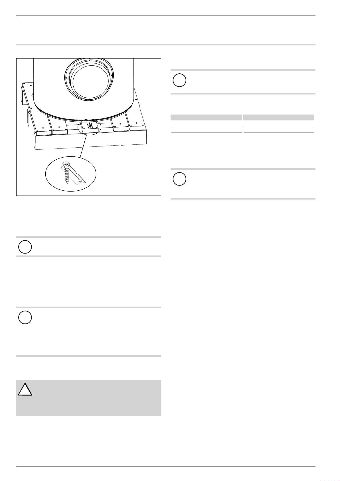
1 Cardboard packaging clips
The appliance is secured to the pallet with metal brackets and
screws. The metal brackets are hooked on to the feet underneath
the floor plate of the appliance.
www.stiebel-eltron-usa.com SB 300-400 E | 7
Page 8
INSTALLATION
Installation
1 Metal bracket fixing screw
f Remove the fixing screw of the metal bracket from the pallet.
f Tilt the appliance to the side for each foot. Screw out the
adjustable tank foot, remove the brackets, and screw in the
adjustable tank foot.
Caution
!
Take note of the appliance's weight and top-heaviness.
f Slightly tip the appliance and carefully roll the appliance off
the pallet.
f Bring the appliance in its final location.
Minimum clearances
f Maintain the minimum clearances.
Caution
!
The appliance must be straightened vertically to avoid
appliance damage.
The feet under the floor plate of the appliance are
height-adjustable.
f Level the appliance horizontally using the height-ad-
justable feet.
10. Installation
WARNING Injury
!
Incorrect installation can lead to serious personal injury.
Before any work, ensure sufficient clearances for the
installation.
Handle sharp-edged components carefully.
10.1 Water connection
Caution
!
Carry out all water connection and installation work in
accordance with local plumbing regulations.
The following material combinations are approved for metal pipework installations:
Cold water inlet DHW outlet
Copper pipe Copper pipe
Steel pipe Steel pipe or copper pipe
f Thoroughly flush the pipework before connecting the ap-
pliance. Foreign bodies, such as welding pearls, rust, sand
or sealant can impair the operational reliability of the
appliance.
Caution
!
To protect the stubs against corrosion the water tube connection must be made with flat gaskets. The use of hemp
on stub threads is not permissible.
Safety valve
The appliance is a sealed unvented DHW tank. Provide the
appliance with a pressure relief valve.
f Install a type-tested safety valve in the T&P port on the side
of the unit. The response pressure of the safety valve must be
below or equal to the permissible operating pressure of the
DHW tank.
The safety valve protects the appliance against unacceptable excess pressure.
f Ensure that the expansion water escaping from the safety
valve can drip into a drain, e.g. a tank or sink.
Ensure the drain cannot be shut off.
f Size the drain in a way that water can drain off unimpeded
when the safety valve is fully opened.
f Ensure that the discharge pipe of the safety valve is open to
atmosphere.
f Fit the discharge pipe of the safety valve with a constant
downward slope and in a room free from the risk of frost.
Pressure reducing valve
The maximum pressure in the cold water supply line must be at
least 20% below the response pressure the safety valve. If the
maximum pressure in the cold water supply line is higher, install
a pressure reducing valve.
Drain valve
f Install a suitable drain valve at the lowest point in the cold
water inlet line.
8 |SB 300-400 E www.stiebel-eltron-usa.com
Page 9
INSTALLATION
Installation
DHW circulation
The heat losses incurred in the DHW circulation line and the electrical power consumption of the circulation pump reduce the efficiency of the system. The cooled water in the circulation line mixes
with the tank content. Where possible, avoid installing a DHW
circulation line. Where that is not possible, the DHW circulation
pump must be controlled thermally or by time switch.
Thermal insulation
f Insulate the DHW line against heat loss in accordance with
locally applicable regulations.
10.2 Heating connection
The heating system can be configured in a variety of ways. The
methods described here are for the most common installation
method. For more questions on installation and configuration of
the heating system, contact Stiebel Eltron.
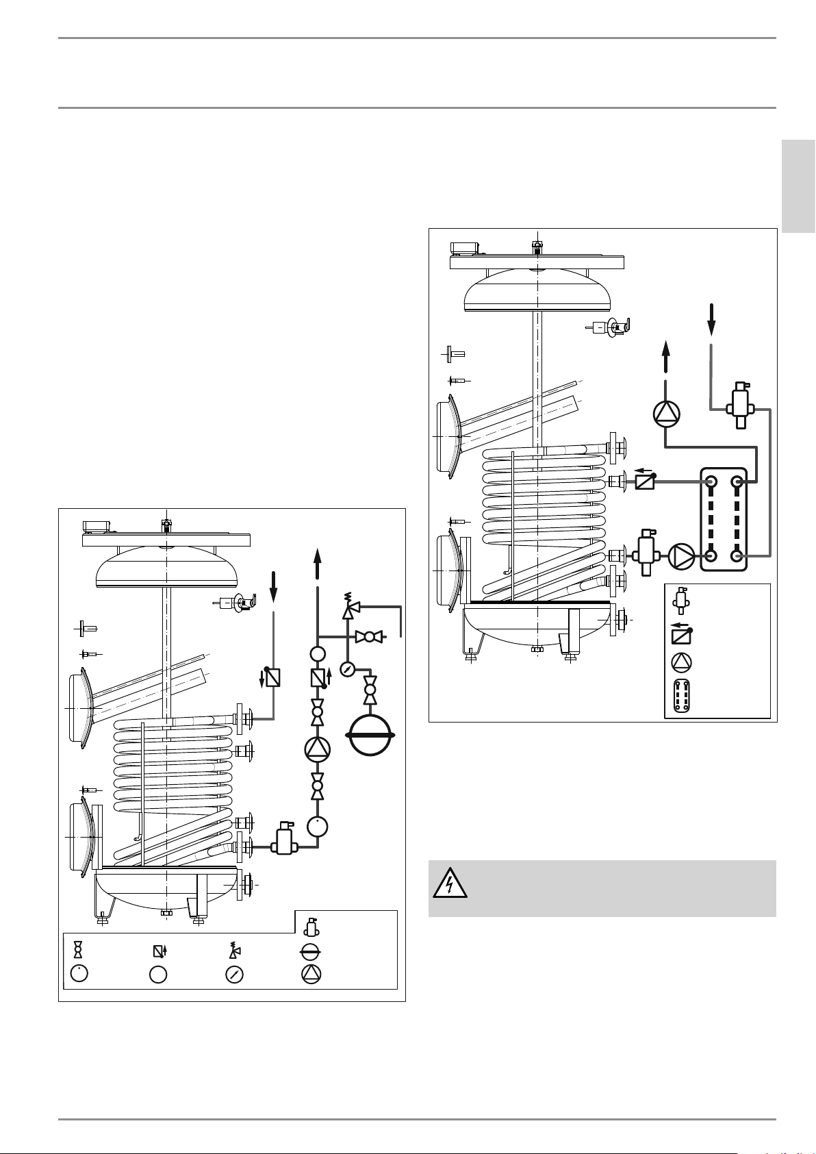
10.2.1 Connecting to the internal coil heat exchanger
The internal coil heat exchanger connections are 1˝ NPT female.
A common use of this coil is for closed-loop solar thermal applications, like in the below image.
To solar
10.2.2 Connecting to the auxiliary ports
The auxiliary ports can be used to add another heating source,
or to supply heat stored in the tank to another location. If the
auxiliary ports are unused for heating, they can be used for a
DHW recirculation loop.
From aux.
heat source
To aux.
heat source
ENGLISH
From solar
V
Ball valve
Flow meter
Check valve
Temp. gauge
T
T&P valve
Pres. gauge
A few necessary features of this system include:
- Corrosion inhibiting propylene glycol
- Air separator/eliminator
- Circulation pump
T
V
Air separator
Expansion tank
Circulation pump
Air/dirt separator
Check valve
Circulation pump
Flat-plate HX
It is necessary for both sides of the heat exchanger to have circulation pumps and air/dirt separators. A check valve is also recommended to prevent thermosiphoning.
Consult your local plumbing code for requirements regarding heat
exchanger properties (double wall, brazed, stainless steel, etc.)
10.3 Power supply
WARNING
Carry out all electrical connection and installation work
in accordance with national and regional regulations.
If the appliance is permanently connected to the power supply,
ensure that the appliance can be separated from the power supply by an isolator that disconnects double terminal with at least
3mm contact gap. Contactors, mains isolators or fuses can be
used for this.
Disconnect the appliance from the power supply before carrying
out work on the control panel. Prevent the power supply from
being switched on while you are working on the system.
Ensure the appliance is earthed according to locally applicable
requirements.
www.stiebel-eltron-usa.com SB 300-400 E | 9
Page 10
INSTALLATION
Commissioning
10.3.1 Installing the power cable
Caution
!
Never connect the appliance to the power supply before
the DHW tank is filled.
The power to this appliance is delivered with a power cable with
a mains plug.
f Use minimum 14/2 (with ground) AWG copper wire for in-
stallation. For long wire lengths, you may need to increase
the gauge size. Always install in accordance with all national
and local electrical codes.
f Unit shall be connected to a 15 A dual pole breaker.
f Using the 14/2 wire (or larger if the code calls for it), connect
the 14/2 wire to the 3 wires in the junction box as shown.
f Use the proper strain relief grommet where the wire enters
the junction box.
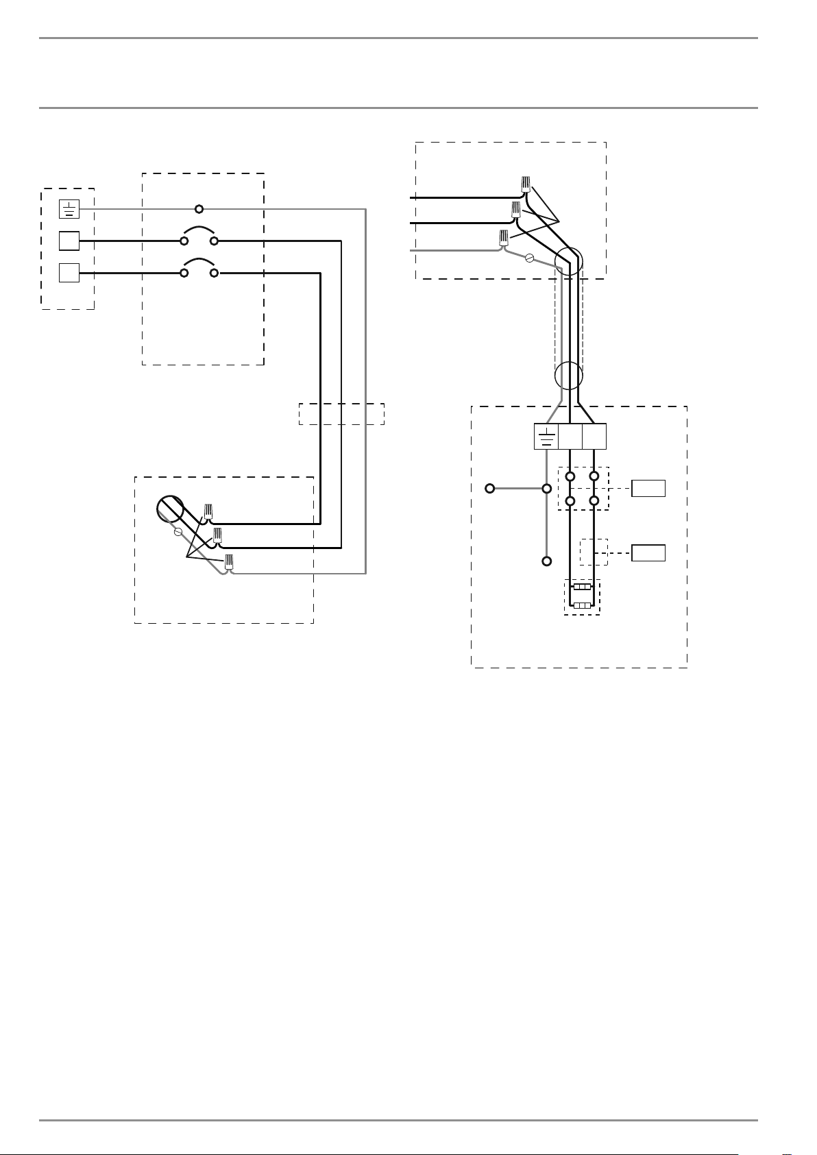
See 15.6, “Wiring diagram”, pg. 16.
11. Commissioning
11.1 Commissioning
Caution
!
Never connect the appliance to the power supply before
the DHW tank is filled.
11.1.1 Filling the DHW tank
Fill the DHW tank and vent the pipework by following the procedure below:
f Close the drain valve.
f Open all DHW tap points and the shut-off valve in the cold
water supply.
f Close the DHW tap points as soon as water starts to emerge
from them.
11.1.2 Appliance handover
f Explain the appliance function to users and familiarize them
with its operation.
f Make users aware of potential dangers, especially the risk of
scalding.
f Make users aware of critical environmental factors and re-
quirements concerning the installation location.
f Inform users that water may drip from the safety valve
during the heating operation.
f Hand over these operating and installation instructions to
users for safe-keeping.
12. Shutting down
Caution
!
If the appliance is disconnected from the power supply,
it is no longer protected against frost.
f Only disconnect the appliance from the power sup-
ply for longer periods if you are also draining the
DHW tank.
If there is no usage of hot water for a long period of time, always
drain the DHW tank. See 14.2, “Draining the tank”, pg. 11.
The appliance can only be switched off by interrupting the power
supply.
f Pull the mains plug from the socket or disconnect the appli-
ance from the mains in the fuse box.
13. Electrical Troubleshooting
WARNING Risk of Electric Shock
Prior to all work on the appliance, isolate it from the
power supply.
Caution
!
If you disconnect the appliance from the power supply, it
is no longer protected against frost.
f Only disconnect the appliance from the power sup-
ply for longer periods if you are also draining the
DHW tank.
f For work on the electric heating element, remove the heating
element cover (See 14.1, “Removing the heating element
cover”, pg. 11).
If the unit does not provide hot water, then the heating element
is likely not heating the water.
1 Check that the circuit breaker is in the on position. Reset if
necessary.
2 Inspect the connections inside the junction box. Repair if
necessary.
3 Check the voltage at the junction box connections. The volt-
age should be 240 VAC.
4 Check for proper resistance of the heating element.
f Turn off circuit breaker.
f Disconnect wire nuts on L1 and L2 and separate wires.
f Measure the resistance between the two black wires going
into the conduit of the tank. It should measure 17.6 Ω ±10%.
f If the measurement is off, there may be an internal wiring
problem or a faulty heating element. Call Stiebel Eltron for
technical support.
11.2 Recommissioning
If the appliance is switched off due to an interruption to the power
supply, no specific measures for restarting are required once the
power supply has been restored.
10 |SB 300-400 E www.stiebel-eltron-usa.com
Note
Refit the heating element cover after completing your
work. See 14, “Maintenance and cleaning”, pg. 11).
Page 11
INSTALLATION
Maintenance and cleaning
13.1 Resetting the high limit safety cut-out
The high limit safety cut-out protects the appliance from overheating. The cut-out switches off the electric element when the tank
water temperature exceeds 199–208 °F (93–98 °C).
Once the cause of the failure has been removed, press the reset
button of the high limit safety cut-out on the rod thermostat. To
do so, remove the appliance cover.
Thermal safety
cut-out
14. Maintenance and cleaning
WARNING
Prior to all work on the appliance, isolate it from the
power supply.
14.1 Removing the heating element cover
f Undo the screws that fasten the heating element cover to the
appliance.
f Pull off the cover.
14.2 Draining the tank
WARNING Burns
Hot water may escape when draining the DHW tank.
To drain the DHW tank, e.g. when shutting the appliance down,
proceed as follows:
f Unplug the appliance from the power supply.
f Close the shut-off valve in the cold water supply line.
The DHW tank is drained via the cold water supply line.
f Open the drain valve installed in the cold water supply line
(See 10.1, “Water connection”, pg. 8). If no drain valve
has been installed, undo the cold water supply line at the
"cold water inlet" connection.
f Open one tap in one sink.
Some residual water will remain in the lower section of the DHW
tank.
14.3 Descaling the electric element
Only descale the flange of the electric booster heater after removing it, and never treat the interior of the DHW tank and the
sacrificial anode with descaling agents.
14.4 Valves
Regularly check the system's valves (safety valve, pressure reducing valve, drain valve, vacuum breaker, mixing valve), to ensure the
operational reliability of the appliance. The amount of limescale
deposits depends on the local water quality.
f Check all valves in the system and remove limescale deposits.
f Replace the valves if necessary.
f Check the function of the valves.
f Whether a sand filter is installed.
14.5 Replacing the electric element cover
ENGLISH
Note
Refit the heating element cover after completing your
work.
www.stiebel-eltron-usa.com SB 300-400 E | 11
WARNING
f Reconnect the earth cable to the appliance cover.
f Place cover back in its original position.
f Secure the screws holding the cover onto the appliance.
Page 12
INSTALLATION
ZĤ¼êÐ|ŒêĒĉń
15. Specifications
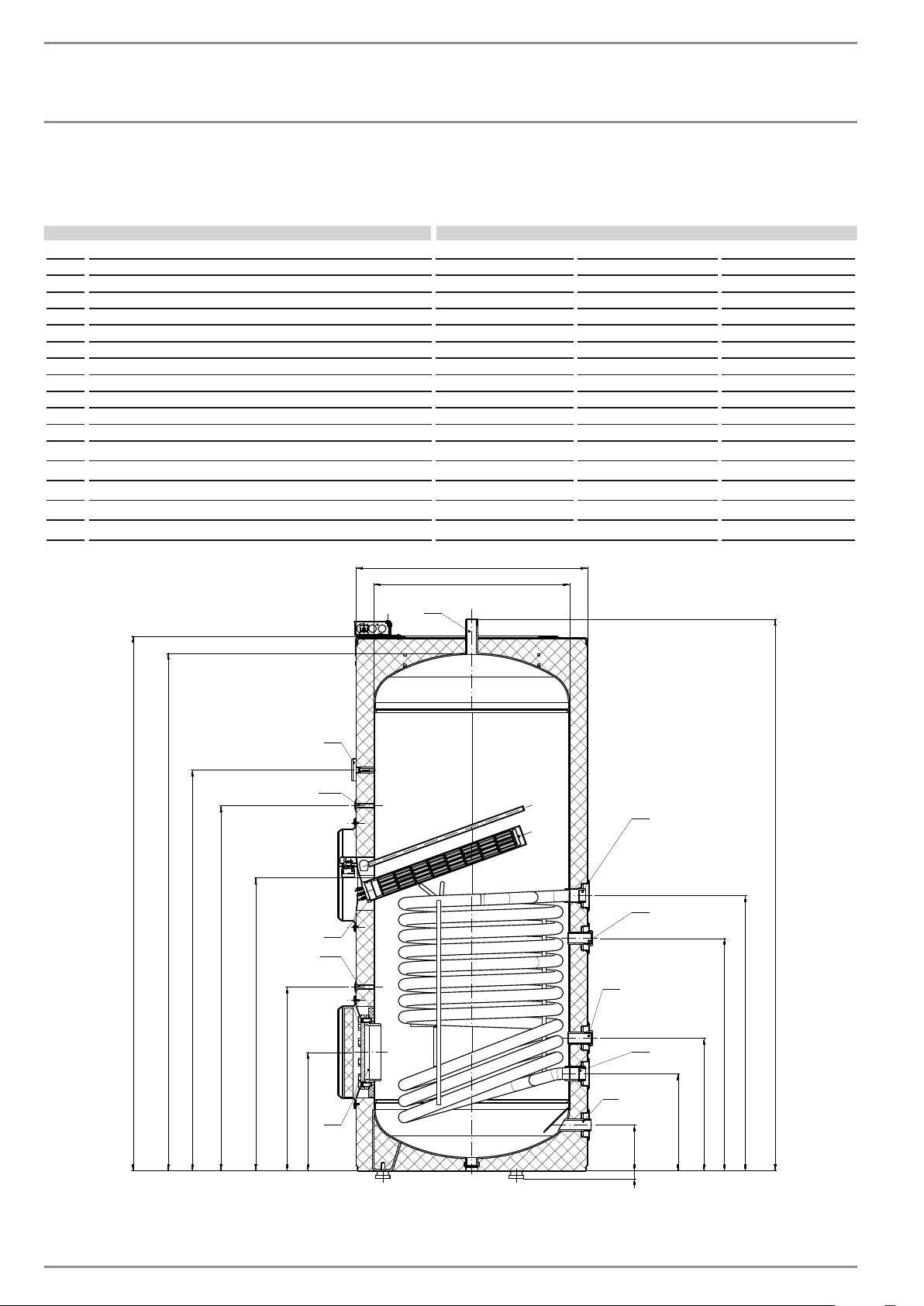
15.1 Dimensions
Type SB 300 E SB 400 E Connection
A Height of tank with insulation 59.1˝ (1501 mm) 59˝ (1500 mm)
B Height of tank without insulation 57.3˝ (1456 mm) 57˝ (1448 mm)
C Height to thermometer 44.4˝ (1128 mm) 45.1˝ (1145 mm)
D Height to upper temperature sensor sleeve 40.5˝ (1028 mm) 42.7˝ (1085 mm) 9 mm
E Height to electric element opening 32.5˝ (825 mm) 34.9˝ (887 mm)
F Height to lower temperature sensor sleeve 23.4˝ (518 mm) 19.6˝ (498 mm) 9 mm
G Height to clean-out port 13.2˝ (335 mm) 12.4˝ (315 mm) 115 mm
H Height to cold water inlet 5.1˝ (129 mm) 4.3˝ (110 mm) 1˝ NPT male
I Height to heat exchanger lower port 10.8˝ (275 mm) 11˝ (280 mm) 1˝ NPT female
J Height to auxiliary heat source lower port 14.8˝ (375 mm) 15˝ (380 mm) 1˝ NP T male
K Height to auxiliary heat source upper port 25.8˝ (655 mm) 28˝ (710 mm) 1˝ NP T male
L Height to heat exchanger upper port 30.5˝ (775 mm) 32.7˝ (830 mm) 1˝ NPT female
M Height to hot water outlet (overall height) 61.1˝ (1552 mm) 60.8˝ (1544 mm) 1˝ NPT male
N Height to T&P valve port 48.3˝ (1228 mm) 48.3˝ (1228 mm) ¾˝ NPT female
O Tank diameter without 21.7˝ (550 mm) 25.6˝ (650 mm)
P Tank diameter with insulation 25.6˝ (650 mm) 29.5˝ (750 mm)
Q Foot height 0.9–1.3˝ (22–34 mm)
P
O
2
5
10
7
A
B
4
11
C
D
8
9
M
E
6
F
G
3
1
I
H
Q
L
K
J
12 |SB 300-400 E www.stiebel-eltron-usa.com
Page 13
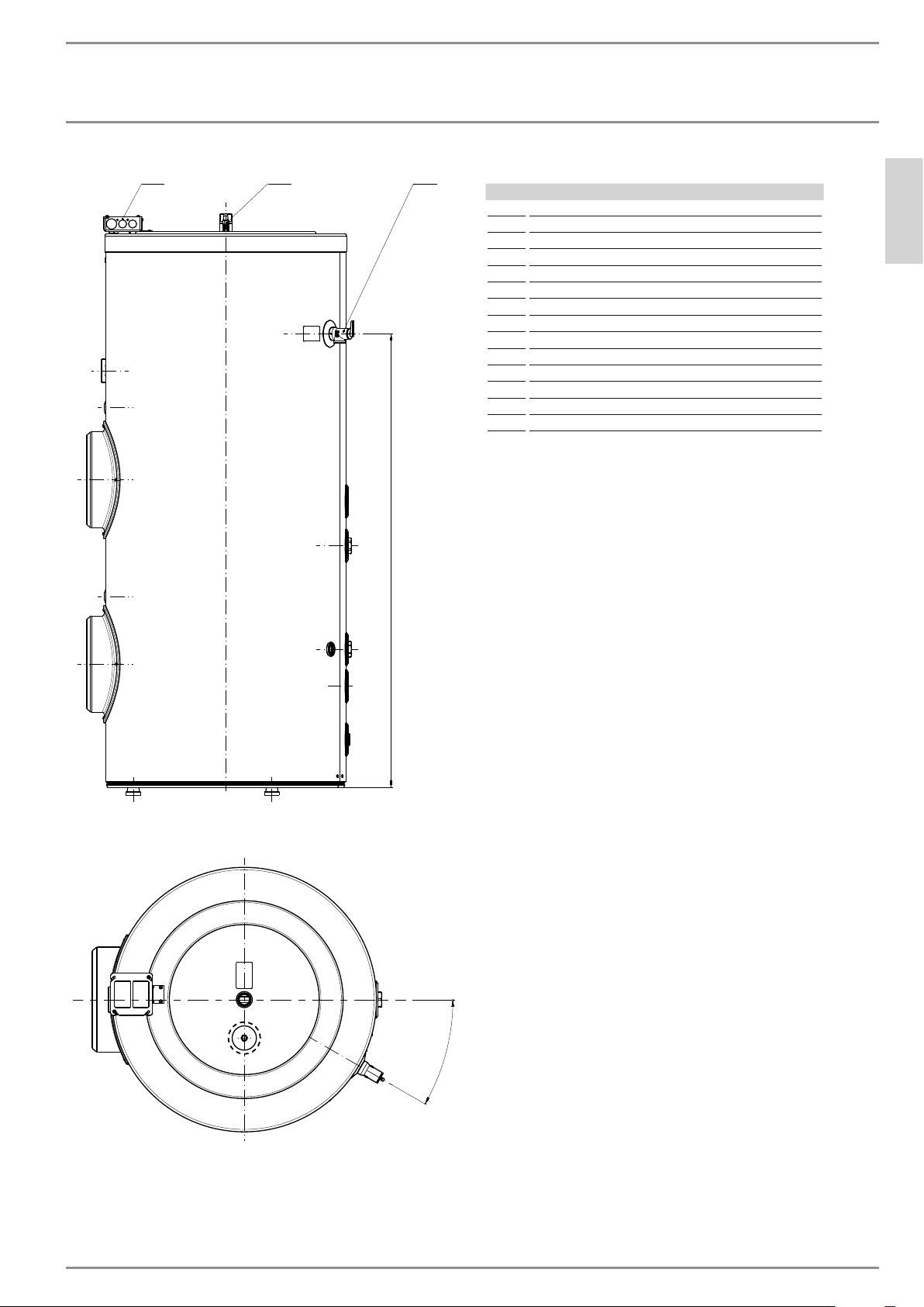
INSTALLATION
ZĤ¼êÐ|ŒêĒĉń
13 14
12
N
15.2 Features
1 Cold water inlet
2 Hot water outlet
3 Clean-out port
4 Electric heating element
5 Analog thermometer
6 Lower heat exchanger port
7 Upper heat exchanger port
8 Lower auxiliary port
9 Upper auxiliary port
10 Upper temperature sensor sleeve
11 Lower temperature sensor sleeve
12 T&P valve port
13 Junction box
14 Anode replacement indicator
ENGLISH
30°
www.stiebel-eltron-usa.com SB 300-400 E | 13
Page 14
INSTALLATION
ZĤ¼êÐ|ŒêĒĉń
15.3 Data table
SB 300 E SB 400 E
234110 234111
Hydraulic data
Nominal capacity 79.3 gal (300 l) 105.6 gal (400 l)
Water volume 77.4 gal (293 l) 109.1 gal (413 l)
Internal coil heat exchanger volume 2.4 gal (9.5 l) 2.9 gal (11.1 l)
Internal coil heat exchanger area 16.1 ft² (1.5 m²) 20.6 ft² (1.9 m²)
Heating element
Heating element voltage 220–240 V
Heating capacity 3.0 kW (10,239 BTU/hr)
Frequency 60 Hz
Rated current 12.5 A
Required circuit breaker 15 A
Heating element type Dome element
Heating element material Ceramic
Temperature control Knob with °F & °C scale under the heating element cover
Set range of thermostat 86–167 °F (30–75 °C)
Miscellaneous
Maximum allowed pressure (tank) 145 psi (10 bar)
Maximum allowed pressure (heat exchanger) 145 psi (10 bar)
Maximum tank temperature 203 °F (95 °C)
Tank heat loss in 24 hours at 149°F / tank temperature 2.8 kWh (9,553 Btu) 3.0 kWh (10,236 Btu)
Empty weight 313 lb (142 kg) 399 lb (181 kg)
Filled weight 1,010 lb (458 kg) 1,334 lb (605 kg)
Type of anode Magnesium with wear indicator
Dimensions
Height
Diameter
Insulation thickness 2 in (50 mm) 2 in (50 mm)
Diameter without insulation
1
61
/ 8 in (1552 mm) 60 13/ 16 in (1544 mm)
9
25
/ 16 in (650 mm)
5
21
/ 8 in (550 mm) 25 9/ 16 in (650 mm)
29 ½ in (750 mm)
14 |SB 300-400 E www.stiebel-eltron-usa.com
Page 15
INSTALLATION
ZĤ¼êÐ|ŒêĒĉń
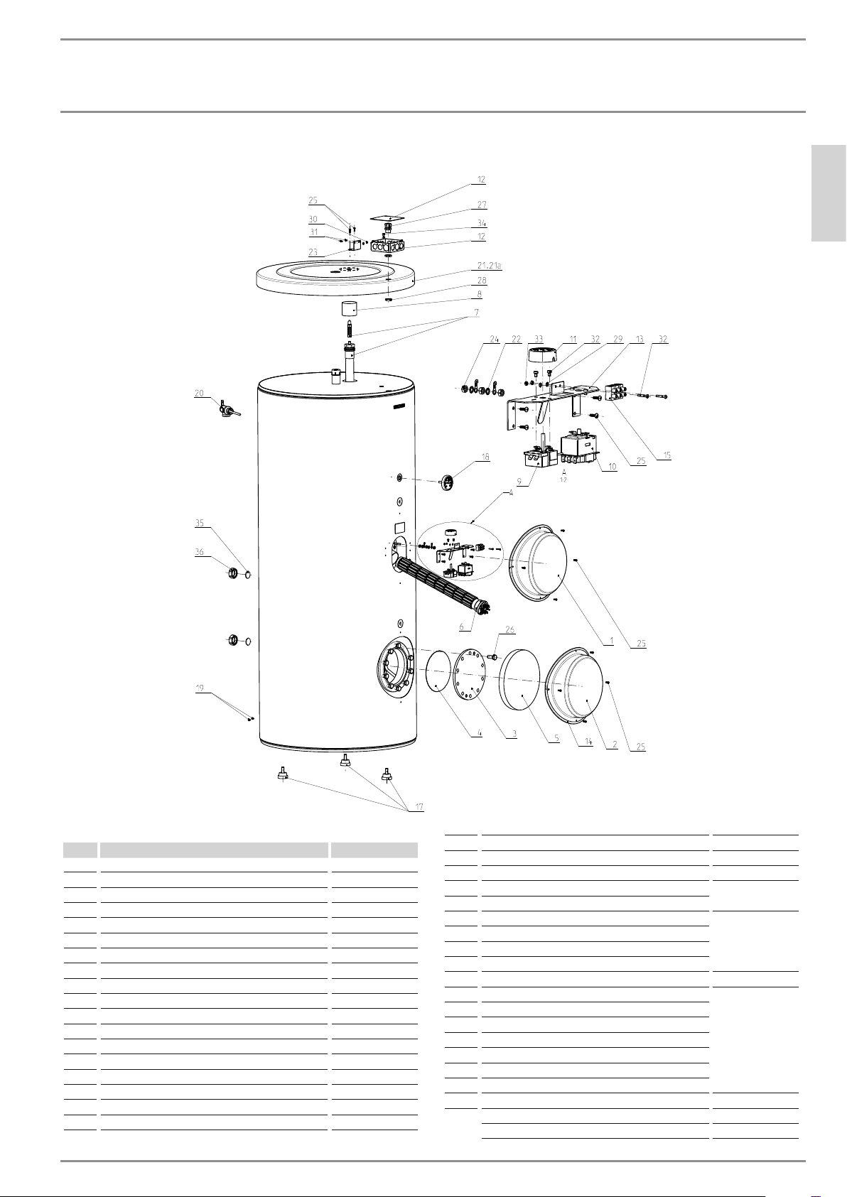
15.4 Spare parts
ENGLISH
15.5 Spare parts list
Name Part #
Pos.
1 Heating element assembly cover 315268
2 Clean-out port cover 315266
3 Flange plate 082357
4 Flange gasket 168662
5 Foam insulation for clean-out port 299891
6 3 kW heating element 296391
7 Segmented sacrificial anode 1¼˝ 143499
8 Anode sleeve 166375
9 Thermostat 269978
10 Thermal safety cut-out 279006
11 Thermostat knob 315423
12 Junction box 4x4˝ 315357
13 Electric element holder 315269
14 Gasket cap 298307
15 Terminal block 309566
16 Connection cable (not shown) 315272
17 Adjustable tank foot 291975
18 Thermometer, 32–248 °F (0–120 °C) 315265
19 Rivets for outer jacket 298745
20 T&P valve 100 psi (6.9 bar) 315664
21 Top cover for SB 300 E 315264
21a Top cover for SB 400 E 315297
22 Washer for thermostat (DIN 6797-A6.4)
23 Junction box holder 315271
24 Nut for thermostat (I4032-M6)
25 Screw for element holder (DIN7981-M4.2x16)
26 M12 12x30-8.8 ISO4017 bolt
27 Cable gland 298306
28 Junction box nut 315287
29 Washer (125-3.2-140HV-ZN)
30 Nut (I4032-M 4-4-A0E)
31 Screw for thermostat (DIN7985-M4x6)
32 Screw for terminal block (I4075-M3-18)
33 Nut for terminal block (I4032-M3-6)
34 Screw (DIN 7500 CE M5x8-Z-AoE)
35 Threaded cap seal 306211
36 Threaded cap 309113
Cable loop 315273
Insulating bushing 315540
www.stiebel-eltron-usa.com SB 300-400 E | 15
Page 16
INSTALLATION
Environment and Recycling
15.6 Wiring diagram
L2
L1
240 VAC
15 A Dual Pole
Circuit Breaker
Breaker Box
Outlet (Optional)
Wire Nuts
Black
Black
Green/Yellow
SB E Junction Box
Black
Black
Green/Yellow
Anode
Outer Casing
Wire Nuts
Tank
L1L2
Wiring Terminal
Safety Cutout
Thermostat
SB E Junction Box
The above wiring diagram shows the connection between the
circuit breaker and the SB E junction box.
Heating Element
SB E Heating Element
The above wiring diagram shows the internal pre-wired connection of the SB E.
16. Environment and Recycling
We ask you to help protect the environment. After use, dispose
of the various materials in accordance with national and local
regulations.
16 |SB 300-400 E www.stiebel-eltron-usa.com
Page 17

WARRANTY | ENVIRONMENT AND RECYCLING
17. Warranty
DHW SOLAR & INDIRECT STORAGE TANKS
All SB 150 S, SB 200 S, SB 300 E, SB 400 E, SBB 300 S, SBB 400 S, SBB 300 Plus, SBB 400 Plus,
& SBB 600 Plus Models
LIMITED WARRANTY
Subject to the terms and conditions set forth in this limited
lifetime warranty, Stiebel Eltron, Inc. (the “Manufacturer”)
hereby warrants to the original purchaser (the “Owner”) that
each storage tank (the “Tank”) shall be free from defects in the
Manufacturer’s materials or workmanship for a period of:
1. (10 Years) from the date of purchase for single, two-, and
three-family residential installations
2. (5 Years) from the date of purchase for all other
installations
3. (Excluded) sacrificial or electronic anode
As Owner’s sole and exclusive remedy for the above warranty,
Manufacturer shall, at the Manufacturer’s discretion, either
factory repair or replace the defective Tank with a replacement
unit or part(s) with comparable operating features.
Manufacturer’s maximum liability under all circumstances shall
be limited to the Owner’s purchase price for the Tank.
This limited warranty shall be the exclusive warranty made by
the Manufacturer and is made in lieu of all other warranties,
express or implied, whether written or oral, including, but
not limited to warranties of merchantability and fitness for
a particular purpose. Manufacturer shall not be liable for
incidental, consequential or contingent damages or expenses
arising directly or indirectly from any defect in the Tank or the
use of the Tank. Manufacturer shall not be liable for any water
damage or other damage to property of Owner arising, directly
or indirectly, from any defect in the Tank or the use of the Tank.
Manufacturer alone is authorized to make all warranties on
Manufacturer’s behalf and no statement, warranty or guarantee
made by any other party shall be binding on Manufacturer.
Manufacturer shall not be liable for any damage whatsoever
relating to or caused by:
1. any misuse or neglect of the Tank, any accident to the Tank,
any alteration of the Tank, or any other unintended use;
2. acts of God and circumstances over which Manufacturer
has no control;
3. installation of the Tank other than as directed by
Manufacturer and other than in accordance with
applicable building codes;
4. improper installation and/or improper materials used
by any installer and not relating to defects in parts or
workmanship of Manufacturer;
5. failure to maintain the Tank or to operate the Tank in
accordance with the Manufacturer’s specifications;
6. failed components not originally installed by the
Manufacturer as a part of the unit at the time of sale;
7. exposure to freezing conditions;
8. exposure to harmful chemicals, contaminated water,
corrosive fluids or atmosphere, liquids harmful to steel
tubing including improperly applied or maintained heat
transfer fluids.
9. utilizing the tank as an open loop heat exchanger, e.g.,
do not use in drainback systems or continually pass fresh
potable water through the units internal heat exchanger.
10. installing the Tank in a closed system without a properly
sized and installed thermal expansion tank;
11. operating the Tank without the factory installed
sacrificial anode;
12. operating the Tank under fluctuating or excessive water
pressure or in the event the Tank is supplied with nonpotable water for any duration;
13. operating the Tank when it is empty or partially full of
potable water;
14. Installing and operating the Tank outdoors;
15. operating the Tank at temperatures higher than
recommended by Manufacturer;
16. (SB E models) replacing the electric heating element
with a unit not manufactured by Stiebel Eltron or greater
in power than the originally installed element;
17. (SB E models) connecting the Tank to improper voltage
or service;
Should owner wish to return the Tank to manufacturer for
repair or replacement under this warranty, Owner must first
secure written authorization from Manufacturer. Owner shall
demonstrate proof of purchase, including a purchase date, and
shall be responsible for all removal and transportation costs.
If Owner cannot demonstrate a purchase date this warranty
shall be limited to the period beginning from the date of
manufacture stamped on the Tank. Manufacturer reserves
the right to deny warranty coverage upon Manufacturer’s
examination of the Tank. This warranty is restricted to the
Owner and cannot be assigned.
Some States and Provinces do not allow the exclusion or
limitation of certain warranties. In such cases, the limitations
set forth herein may not apply to the Owner. In such cases this
warranty shall be limited to the shortest period and lowest
damage amounts allowed by law. This warranty gives you
specific legal rights and you may also have other rights which
vary from State to State or Province to Province.
Owner shall be responsible for all labor and other charges
incurred in the removal or repair of the Tank in the field. Please
also note that the Tank must be installed in such a manner that
if any leak does occur, the flow of water from any leak will not
damage the area in which it is installed.
ENGLISH
17 West Street
This Warranty is valid for all purchases on or after June 15, 2019.
This Warranty is valid for U.S.A. & Canada only. Warranties
may vary by country. Please consult your local Stiebel Eltron
Representative for the Warranty for your country.
West Hatfield, MA 01088
TOLL FREE 800.582.8423
PHONE 413.247.3380
FAX 413.247.3369
@
stiebel-eltron-usa.com
info
www.stiebel-eltron-usa.com
www.stiebel-eltron-usa.com SB 300-400 E | 17
Page 18

ÍNDICE | FUNCIONAMIENTO
INFORMACIÓN ESPECIAL
FUNCIONAMIENTO
1. Información general __________________________________ 19
2. Seguridad ______________________________________________ 19
2.1 Uso correcto _______________________________________________ 19
2.2 Uso incorrecto _____________________________________________ 19
2.3 Instrucciones generales de seguridad ________________ 19
2.4 Circuito del intercambiador del agua _________________ 19
2.5 Símbolos de prueba ______________________________________ 20
3. Registre su producto _________________________________ 20
4. Descripción del artefacto _____________________________ 20
4.1 Calentamiento del tanque de agua ___________________ 20
5. Uso del calentador eléctrico de refuerzo ___________ 20
6. Cuidado y mantenimiento ____________________________ 21
6.1 Válvula de alivio de temperatura / presión __________ 21
6.2 Descalcificación ___________________________________________ 21
6.3 Reemplazo del ánodo de sacrificio ____________________ 21
7. Resolución de problemas de plomería _____________ 21
7.1 Informar a un técnico calificado _______________________ 22
7.2 Etiqueta de seguridad ___________________________________ 22
8. Seguridad ______________________________________________ 22
8.1 Instrucciones generales de seguridad ________________ 22
8.2 Instrucciones, normas y regulaciones ________________ 23
9. Preparativos ___________________________________________ 23
9.1 Transporte __________________________________________________ 23
9.2 Almacenamiento __________________________________________ 23
9.3 Configuración de la entrega ____________________________ 23
9.4 Lugar de instalación ______________________________________ 23
9.5 Colocación del artefacto _________________________________ 24
10. Instalación _____________________________________________ 25
10.1 Conexión de tuberías ____________________________________ 25
10.2 Conexión de calentamiento _____________________________ 25
10.3 Suministro eléctrico ______________________________________ 26
11. Puesta en marcha _____________________________________ 27
11.1 Puesta en marcha ________________________________________ 27
11.2 Reinicio _____________________________________________________ 27
12. Apagado ________________________________________________ 27
13. Resolución de problemas eléctricos ________________ 27
13.1 Reinicio después del corte de seguridad por
exceso del límite de temperatura _____________________ 28
14. Limpieza y mantenimiento ___________________________ 28
14.1 Remoción de la cubierta del calentador de
refuerzo _____________________________________________________ 28
14.2 Drenaje del tanque _______________________________________ 28
14.3 Limpieza del depósito de cal del calentador
eléctrico de refuerzo _____________________________________ 28
14.4 Válvulas _____________________________________________________ 28
14.5 Remplazo de la cubierta del calentador eléctrico
de refuerzo _________________________________________________ 28
15. Especificaciones _______________________________________ 29
15.1 Dimensiones ______________________________________________ 29
15.2 Características ___________________________________________________ 30
15.3 Tabla de datos ___________________________________________________ 31
15.4 Repuestos ________________________________________________________32
15.5 Lista de repuestos ______________________________________________ 32
15.6 Diagrama de instalación eléctrica
_____________________________________________________________________ 33
16. Medio ambiente y reciclaje _______________________________ 33
INFORMACIÓN
ESPECIAL
- Respete todas las regulaciones e instrucciones nacionales y
regionales pertinentes durante la instalación.
- El artefacto no es apto para instalar en exteriores.
- Si el artefacto está permanentemente conectado al suministro eléctrico, se debe establecer una manera de separarlo de
la red eléctrica mediante un aislante que desconecte todos
los polos con al menos 4 mm (1/8˝) de distancia entre contactos. Para ello, es posible usar contactores, interruptores
de desconexión o disyuntores.
- Respete las regulaciones de seguridad para evitar el contacto
con piezas peligrosas que conduzcan la electricidad.
- El artefacto se encuentra presurizado al expandirse el agua
durante el proceso de calentamiento, parte del agua escapará por la válvula de seguridad.
- Active con regularidad la válvula de seguridad para evitar
que se bloquee, por ejemplo, por depósitos de cal.
- Instale una válvula de seguridad testeada para el tipo específico en la red de suministro de agua fría.
- La presión máxima de la red de suministro de agua fría debe
ser al menos un 20% menor que la presión de respuesta de
la válvula de seguridad. Si la presión máxima de la red de
suministro de agua fría supera la presión de respuesta de
la válvula de seguridad, instale una válvula de reducción de
presión.
- El drenaje debe tener un tamaño suficiente para que el agua
pueda drenar de forma ininterrumpida cuando la válvula de
seguridad está totalmente abierta.
- Instale el tubo de descarga de la válvula de seguridad con
una pendiente descendiente constante y en una habitación
que lo proteja contra la escarcha.
- La abertura de descarga de la válvula de seguridad debe
tener salida al aire libre.
- La presión del circuito del intercambiador de calor nunca
debe fijarse de manera que supere a la presión de la red de
suministro de agua (doméstica) potable. En caso de que la
presión del agua potable sea demasiado baja, es posible que
deba utilizar una bomba de refuerzo a fin de garantizar que
supere la presión requerida del circuito del intercambiador
de calor.
18 |SB 300-400 E www.stiebel-eltron-usa.com
Page 19

FUNCIONAMIENTO
Información general
FUNCIONAMIENTO
1. Información general
Los capítulos “Información especial” y “Funcionamiento” están
destinados a usuarios e instaladores autorizados.
El capítulo “Instalación” está destinado solo a instaladores autorizados.
Nota
Lea estas instrucciones atentamente antes de usar el artefacto y consérvelas para consultas futuras.
Entregue las instrucciones a cualquier nuevo usuario que
las necesite.
2. Seguridad
2.1 Uso correcto
El artefacto está diseñado para el calentamiento del agua doméstica dentro de los límites de aplicación. Véase 15.3, “Tabla de
datos”, pág. 31
El artefacto está diseñado para el uso doméstico, es decir, no hace
falta un entrenamiento especial para utilizarlo con seguridad. El
artefacto también puede usarse en un entorno no doméstico, por
ejemplo una pequeña empresa, con la condición de que se utilice
de la misma manera.
Cualquier otro uso que no esté estipulado se considerará inapropiado. El cumplimiento de estas instrucciones y de las instrucciones de uso de cualquier accesorio también forma parte del uso
correcto del calentador.
2.2 Uso incorrecto
Los siguientes usos no están permitidos:
- Calentar otro líquido que no sea agua potable
- Hacer funcionar el artefacto con el tanque de agua vacío
- Hacer funcionar el artefacto fuera de los límites de aplicación
(Véase 15, “Especificaciones”, pág. 29)
- Interrumpir el suministro de electricidad
2.3 Instrucciones generales de seguridad
Solo los instaladores autorizados deben realizar los trabajos relacionados con la electricidad y la instalación de este artefacto. Los
instaladores autorizados son responsables de cumplir con todas
las regulaciones pertinentes.
Haga funcionar el artefacto solo cuando se haya completado la
instalación y tenga incorporados todos los elementos de seguridad.
ADVERTENCIA
El contacto con partes que conducen electricidad pone
en riesgo la vida. Los daños en el aislante eléctrico o
las piezas individuales pueden poner en riesgo la vida.
f Si existen daños en el aislante, corte el suministro
de electricidad y solicite una reparación.
Todos los trabajos relacionados con la electricidad deben
ser llevados a cabo por un electricista calificado.
ADVERTENCIA Quemaduras por agua caliente
El agua del tanque puede calentarse hasta alcanzar temperaturas que superan los 149 °F (65 °C). Existe el riesgo
de quemaduras por agua caliente cuando la temperatura
del agua que sale supera los 110 °F (43 °C).
f Asegúrese de no entrar en contacto con el agua que
sale durante la descarga.
ADVERTENCIA Quemaduras
El contacto con piezas calientes puede causar quemaduras.
Cuando trabaje cerca de las piezas calientes, utilice
siempre indumentaria de protección y guantes de seguridad.
Las tuberías conectadas a la salida de agua caliente del
artefacto pueden alcanzar temperaturas superiores a
los 149 °F (65 °C).
PRECAUCIÓN
!
Instale equipos de protección de la temperatura y la presión requeridos por los códigos locales y al menos una
válvula combinada de alivio de temperatura y presión
certificada por un laboratorio de pruebas reconocido
a nivel nacional que realice inspecciones periódicas de
la producción de los equipos o materiales enumerados,
cumpliendo con los requisitos para Válvulas de Alivio y
Artefactos de Cierre de Gas Automáticos para Sistemas
de Suministro de Agua Caliente, ANSI Z21.22. Esta válvula debe marcarse con una presión de ajuste máxima
que no supere la presión de trabajo máxima marcada del
calentador de agua. Instale la válvula en una abertura
provista y marcada para este propósito en el calentador
de agua, y oriéntela o instale las tuberías de manera
que cualquier escape de la válvula salga solo a 152 mm
(6 pulgadas) por encima, o a cualquier distancia por debajo del piso estructural, y que no entre en contacto con
ninguna pieza que conduzca electricidad.
Precaución
!
Haga funcionar el artefacto solamente con el tanque de
agua lleno.
Precaución
!
Mantenga el ambiente donde se instaló el artefacto libre
de aire contaminado con aceite o sales, o sustancias corrosivas o explosivas.
ESPAÑOL
2.4 Circuito del intercambiador del agua
Los tanques SB E cuentan con un circuito del intercambiador de
calor a fuego indirecto. Puede utilizarse en diversos entornos que
incluyen circuitos de caldera, sistemas geotérmicos, circuitos de
www.stiebel-eltron-usa.com SB 300-400 E | 19
Page 20

FUNCIONAMIENTO
Registre su producto
piso radiante, etc. Debido a que el interior del intercambiador de
calor es de acero al carbono no revestido, debe configurarse en
un circuito cerrado.
Utilizar únicamente una mezcla de propilenglicol inhibido y agua
desionizada. El porcentaje de glicol en la muestra depende del
ambiente. Algunas áreas requieren que el propilenglicol sea reconocido generalmente como seguro (GRAS), es decir, un líquido
apto para uso alimentario (Intercambiador de calor tipo SW, Líquido Clase II de la Asociación Estadounidense de Obras Hidráulicas
– véase la Hoja de datos sobre la seguridad de los materiales para
conocer las instrucciones de manipulación.
2.5 Símbolos de prueba
Véase 7.1.1, “Ejemplo de placa de identificación”, pág. 22
3. Registre su producto
NOTA:
Debe registrar este producto en un plazo de 90 días
desde la compra a través de nuestra página web para
activar cualquier garantía estándar o para optar a la
ampliación de la garantía. Visite nuestra página web
www.stiebel-eltron-usa.com y haga clic en “Registre
su producto”.
Antes de comenzar el proceso de registro, le sugerimos que recopile la siguiente información que necesitará:
Modelo; ejemplo: SB 300 E (tomado de la etiqueta situada en el
lado de la unidad)
Número que se indica después de “Nr.”
Lugar de compra
Fecha de compra
Nombre y apellido
Dirección de email
Dirección postal
Número de teléfono
Si tiene alguna pregunta en relación con el proceso de registro
o con las opciones de garantía, por favor, póngase en contacto
directamente con Stiebel Eltron USA en el número de teléfono
800.582.8423.
4. Descripción del artefacto
El calentador está diseñado para instalarse en interiores. El artefacto está equipado para calentar agua mediante varios métodos
de calentamiento diferentes.
La unidad puede calentar agua de las siguientes tres maneras:
- Calentador de refuerzo por resistencia eléctrica de 3 kW
- Calor indirecto mediante intercambiador de calor con espiral
interno
- Calor indirecto mediante puertos auxiliares de entrada/salida
Todo el calentador y el sistema de agua caliente deben llenarse
con agua y tener una ventilación de aire adecuada. En caso de
utilizar los colectores solares y las calderas, sírvase consultar las
instrucciones de instalación de los mismos.
4.1 Calentamiento del tanque de agua
El primer método de calentamiento es mediante el calentador de
refuerzo por resistencia eléctrica de 3 kW. Este es el funcionamiento más básico del calentador.
Un sensor de temperatura integral detecta el contenido de energía térmica de la cantidad de calor dentro del tanque de agua. El
agua del tanque se calienta si la cantidad de calor es inferior a la
requerida para alcanzar la temperatura fijada.
El segundo método de calentamiento es mediante el intercambiador de calor con espiral interno. Este intercambiador de calor está
diseñado para que un líquido de transferencia de calor circule a
través de él desde un calentador indirecto. Este calentador indirecto puede consistir en un sistema térmico solar, una caldera u
otro artefacto tradicional de circuito cerrado que genera calor y
lo transfiere a través de un líquido de transferencia de calor con
inhibición de la corrosión.
El tercer método de calentamiento es mediante puertos auxiliares
ubicados del lado de la unidad. Estos puertos auxiliares proporcionan acceso directo al agua doméstica que se encuentra en
el tanque. Debe utilizarse un intercambiador de calor de placa
plana para intercambiar calor entre un calentador indirecto y el
agua del tanque.
Si alguno de los últimos dos métodos de calentamiento requiriese un sensor de temperatura, del lado opuesto del tanque se
proporcionan 2 puertos de las conexiones auxiliares y del intercambiador de calor.
5. Uso del calentador eléctrico de
refuerzo
Este producto viene equipado con un calentador eléctrico de refuerzo de 3 kW. El calentador de refuerzo cuenta con una sonda
de temperatura integrada que detecta la temperatura del agua
del tanque.
El elemento calefactor eléctrico 3 kW viene ajustado de fábrica
a 125 °F (52 °C). El valor de referencia del calentador de refuerzo
puede cambiarse fácilmente. Debajo del calentador de refuerzo,
hay una perilla que puede cambiar el nivel de comodidad para
adaptarse a las necesidades del usuario.
El calentador de refuerzo puede desenchufarse durante un periodo de desuso o puede removerse por completo.
Por comodidad, el calentador de refuerzo puede removerse del
tanque sin drenarlo.
20 |SB 300-400 E www.stiebel-eltron-usa.com
Page 21

FUNCIONAMIENTO
Cuidado y mantenimiento
Perilla del termostato
Muesca del
punto de
referencia
6. Cuidado y mantenimiento
El cuidado y mantenimiento de rutina extienden la vida útil y la
seguridad de funcionamiento de la unidad de almacenamiento
de agua caliente. El exterior debe limpiarse con un trapo un poco
húmedo y con un producto de limpieza neutro disponible en el
mercado. Esto debe hacerse con regularidad.
ADVERTENCIA
Nunca rocíe el artefacto con agua.
Nunca rocíe agua dentro del artefacto.
ADVERTENCIA Lesiones
!
Solo un técnico calificado debe efectuar las tareas de
mantenimiento, como las verificaciones eléctricas de
seguridad.
Componentes del
artefacto
Exterior
Tanque de agua
Calentador por resistencia eléctrica
Consejos para el cuidado y mantenimiento
Use un trapo húmedo para limpiar las secciones exteriores. Nunca use productos de limpieza abrasivos
o corrosivos.
El tanque de agua está equipado con un ánodo de
sacrificio y un indicador de desgaste que protege el
tanque de la corrosión. El indicador de desgaste debe
revisarse con regularidad. De otra manera existe el
riesgo de corrosión.
Verifique el estado del calentador por resistencia
eléctrica. Esto extenderá la vida útil del calentador
de refuerzo.
6.1 Válvula de alivio de temperatura / presión
ADVERTENCIA: La válvula de alivio de temperatura y
!
presión está diseñada para aliviar la presión acumulada en el calentador de agua. El líquido puede descargarse a
una temperatura y/o presión elevadas. Es posible que se produzcan lesiones por quemaduras con agua caliente.
Es necesario hacer funcionar correctamente la válvula de alivio de
temperatura y presión a fin de evitar que la unidad de almacenamiento de agua caliente se dañe. Durante el llenado de la unidad
con agua fría, la válvula de temperatura y presión debe estar
abierta. Cuando el agua fluye a raudales de la línea de alivio, el
tanque se encuentra lleno, y la válvula de temperatura y presión
puede volver a colocarse en su posición normal.
6.2 Descalcificación
Con agua de red dura, se formará un depósito de sarro en el interior de la unidad de almacenamiento. En base a la experiencia
profesional, es necesario descalcificarla con disolventes disponibles en el mercado a intervalos oportunos. Siga las instrucciones
del fabricante para el uso de disolventes. Para realizar este proceso, la unidad de almacenamiento de agua caliente debe vaciarse.
La cubierta del puerto de limpieza debe retirarse y los sedimentos
del fondo del tanque deben enjuagarse.
6.3 Reemplazo del ánodo de sacrificio
Según la composición del agua de red, se recomienda realizar
una inspección del ánodo de sacrificio a intervalos oportunos.
Con el uso intenso, deberá instalarse un ánodo de reemplazo del
equipo original para proteger el envase interior de la corrosión.
Debe llevarse a cabo una inspección al menos una vez por año.
7. Resolución de problemas de
plomería
Problema Causa Solución
Presión de agua
insuficiente
Flujo de
agua caliente
insuficiente
El tanque de
almacenamiento
de agua caliente
no se calienta
Velocidad de
flujo del grifo
insuficiente
El suministro de
agua caliente se
agotó demasiado rápido
La válvula de cierre no está
completamente abierta.
O
La red de suministro de agua
caliente o fría está obstruida.
La temperatura de referencia
de la caldera indirecta es demasiado baja.
Se recomienda una temperatura de 176 a 185 °F (80 a
85 °C).
O
El intercambiador de calor se
encuentra calcificado.
La selección del programa en
el control del calentador no
es adecuada.
El aireador del punto de extracción está bloqueado.
La velocidad de flujo es muy
alta. Se recomienda un volumen de 9.8 a 14.7 litros/
minutos (2.6 a 3.9 gpm).
Abra la válvula de cierre.
Limpie o reemplace las tuberías.
Fije la caldera en la temperatura recomendada.
O
Limpie el intercambiador de
calor.
Seleccione y configure el
programa de acuerdo con las
instrucciones.
Desenrosque el aireador y
límpielo
Restringir la velocidad de la
válvula del grifo.
ESPAÑOL
www.stiebel-eltron-usa.com SB 300-400 E | 21
Page 22

INSTALACIÓN
Seguridad
7.1 Informar a un técnico calificado
Si usted no puede solucionar la falla, informe a un técnico calificado. Para facilitar y agilizar su solicitud, proporcione el número de
serie que se encuentra en la placa de identificación de la unidad
(000000-0000-00000). La placa de identificación se encuentra a
la izquierda, arriba de la conexión de salida de agua caliente
(“DHW outlet”).
7.1.1 Ejemplo de placa de identificación
Made in EU
Hecho en EU
Fabriqué en EU
SB 300 E
M-NO.: 234110
S-NO.:
Technical data
Datos técnicos
Données techniques
Volume:
Volumen:
Volume:
293 l / 77.4 gal
Supply:
Alimentación:
Alimentation:
220-240 V AC, 60 Hz
SINGLE PHASE L-L ONLY
Power:
Potencia:
Puissance:
3 kW / 10,239 BTU/h
Max. pressure:
Presión máxima:
Pression max:
1 MPa / 145 PSI
Testing pressure:
Presión de prueba:
Pression d'essai:
1.5 MPa / 217 PSI
Standby loss:
Pérdida de calor:
Pertes en mode de veille:
2.8 kWh/24h
Heat exchanger
Intercambiador de calor
Échangeur de chaleur
Max. pressure:
Presión máxima:
Pression max.:
1 MPa / 145 PSI
Heating surface:
Superficie de calefacción:
Surface de chauffe:
2
1.5 m
Volume:
Volumen:
Volume:
Max. temp.:
Temperatura máxima:
Temp. max.:
/ 16.1 ft
9.5 l / 2.37 gal
95 °C / 203 °F
4010487
Conforms to UL STD. 174
Certified to CAN/CSA STD. C22.2 No.110-94
Made in EU
Hecho en EU
Fabriqué en EU
2
315277-38053
SB 400 E
M-NO.: 234111
S-NO.:
Technical data
Datos técnicos
Données techniques
Volume:
Volumen:
Volume:
413 l / 109.1 gal
Supply:
Alimentación:
Alimentation:
220-240 V AC, 60 Hz
SINGLE PHASE L-L ONLY
Power:
Potencia:
Puissance:
3 kW / 10,239 BTU/h
Max. pressure:
Presión máxima:
Pression max:
1 MPa / 145 PSI
Testing pressure:
Presión de prueba:
Pression d'essai:
1.5 MPa / 217 PSI
Standby loss:
Pérdida de calor:
Pertes en mode de veille:
3.0 kWh/24h
Heat exchanger
Intercambiador de calor
Échangeur de chaleur
Max. pressure:
Presión máxima:
Pression max.:
1 MPa / 145 PSI
Heating surface:
Superficie de calefacción:
Surface de chauffe:
Volume:
Volumen:
Volume:
Max. temp.:
Temperatura máxima:
Temp. max.:
Conforms to UL STD. 174
Certified to CAN/CSA STD. C22.2 No.110-94
2
/ 20.6 ft
1.92 m
11.1 l / 2.9 gal
95 °C / 203 °F
4010487
2
315298-38054
7.2 Etiqueta de seguridad
CAUTION
To reduce the risk of electric shock or fire use only on a utility supply
having a maximum 250 volt, three wire system.
CAUTION
Risk of Electric Shock. Connect branch circuit equipment grounding
means to water heater. For detailed information, refer to instructions.
CAUTION
Risk of Electric Shock and Fire Hazard. Do not connect to supply
by extension cord.
FOR INSTALLED RATING SEE ELEMENT MARKING
Install temperature and pressure protective equipment required by
local codes, but not less than a combination temperature and
pressure relief valve certified as meeting the requirements for Relief
Valves and Automatic Gas Shutoff Devices for Hot Water Supply
Systems, ANSI Z21.22, by a nationally recognized testing laboratory
that maintains periodic inspection of production of listed equipment
or materials. The valve must be oriented, provided with tubing, or
otherwise installed so that discharge can exit only within 6 inches
(15 cm) above, or at any distance below, the structural floor, and
cannot contact any live electrical part.
CAUTION
If the water heater is retrofitted with supplemental heating
equipment, you must adjust both the thermostat controlling the
supplemental heat source (located in the water piping) and the
thermostat on the water heater (behind the access panel) to the
same temperature. Failure to adjust both thermostats to the same
temperature can cause loss of proper temperature control.
When a supplemental heat source is connected to the
appliance, a provision must be made to limit the heat
source temperature not to exceed that of the water heater
thermostat setting.
Etiqueta de seguridad en el aparato.
INSTALACIÓN
8. Seguridad
Los trabajos de instalación, verificación, puesta en marcha y reparación del artefacto solo deben ser realizados por un técnico
calificado.
8.1 Instrucciones generales de seguridad
Para evitar reclamos durante el período de garantía, use solo
accesorios y repuestos originales. Si necesita repuestos, comuníquese con el 800.582.8423.
22 |SB 300-400 E www.stiebel-eltron-usa.com
Page 23

INSTALACIÓN
Preparativos
8.2 Instrucciones, normas y regulaciones
Nota
Respete todas las regulaciones e instrucciones nacionales
y regionales pertinentes.
Observe la placa de identificación del artefacto y lea atentamente
el capítulo “Especificaciones”. Véase 15, “Especificaciones”, pág.
29.
9. Preparativos
9.1 Transporte
PRECAUCIÓN Lesiones
!
f Observe el peso del artefacto.
f Use accesorios de transporte adecuados (por ejem-
plo, una carretilla de carga) y disponga de personal
suficiente para el transporte.
Precaución
!
El artefacto es sumamente pesado.
f Asegúrese de que la unidad no quede inclinada.
f Solo coloque el aparato sobre una base uniforme.
No desempaque el artefacto hasta que se encuentre en el lugar
de instalación final.
Mantenga el artefacto dentro de su embalaje y en el pallet. Ello
permite mantener la posición horizontal y tomar descansos durante el traslado.
Transporte vehicular
Precaución
!
En general, el artefacto debe almacenarse y transportarse en posición vertical.
f Respete las indicaciones que se incluyen en el embalaje.
1
1 Manijas incorporadas
Traslado desde el vehículo hasta el lugar de instalación
La caja de cartón cuenta con manijas reforzadas en la parte superior. Es posible usar las manijas, así como el pallet del extremo
inferior, para trasladar el artefacto hasta el lugar de instalación.
Observe el peso del artefacto y asegúrese de que haya personal
suficiente para manipularlo con seguridad.
9.2 Almacenamiento
Si es necesario almacenar el artefacto durante un período prolongado antes de su instalación, respete las siguientes recomendaciones:
- Almacene el artefacto únicamente en posición vertical.
Nunca almacene el artefacto en posición horizontal.
- Almacene el artefacto en un lugar seco y libre de polvo.
- Evite que el artefacto entre en contacto con sustancias
corrosivas.
9.3 Configuración de la entrega
El tanque de almacenamiento de agua caliente viene con los siguientes equipos:
- Unidad de almacenamiento
- Intercambiador de calor de tubos soldados de acero con extremos lisos
- Protección contra la corrosión por agua caliente con revestimiento de esmalte especial
- Tres vainas de inmersión para almacenar las sondas de
temperatura
- Ánodo de sacrificio de magnesio
- Puerto de circulación
- Dos puertos de calentamiento auxiliares
- Tapa para inspección de la brida conectada
- Aislante de espuma de poliuretano de 5 cm (2 pulgadas) de
espesor
- Cubierta exterior de acero
9.4 Lugar de instalación
El artefacto no es apto para instalar en exteriores, excepto garajes.
Otros requerimientos relacionados con el lugar de instalación y el
posicionamiento del artefacto, para evitar que se dañe el artefacto:
- El lugar de instalación debe estar libre de gases y sustancias
inflamables y altamente combustibles, así como de niveles
altos de polvo.
- En el lugar de instalación no debe existir riesgo de escarcha.
- El piso del lugar de instalación debe estar nivelado y debe
tener suficiente capacidad para soportar el peso del artefacto. Observe el peso del artefacto con el tanque de agua
lleno (Véase 15.3, “Tabla de datos”, pág. 31). Si el piso no
tiene capacidad suficiente para soportar el peso, podría derrumbarse. Si el artefacto no está correctamente equilibrado,
podría dañarse.
D0000034797
- Siempre deje una distancia suficiente que permita el acceso
para la instalación, el mantenimiento y la limpieza. Respete
las distancias mínimas de seguridad (Véase 9.5, “Colocación
del artefacto”, pág. 24).
ESPAÑOL
www.stiebel-eltron-usa.com SB 300-400 E | 23
Page 24

INSTALACIÓN
Preparativos
- Asegúrese de que no se vea afectado el funcionamiento
de ningún otro equipo que se encuentre en el lugar de
instalación.
- Para reducir la longitud requerida del tubo conectado, instale la unidad muy cerca del lugar.
Los siguientes lugares de instalación no están permitidos, debido
al riesgo de que se dañe el artefacto:
- Lugares donde el aire está contaminado con aceite o sales
- Ambientes salinos
- Áreas próximas a máquinas de alta frecuencia
- Lugares donde el aire contiene amoníaco (por ejemplo, plantas de tratamiento de aguas residuales)
- Lugares donde el aire contiene cloro (por ejemplo, piscinas)
- En general, lugares donde el aire está altamente contaminado, por ejemplo, debido al polvo o a la presencia de sustancias agresivas
9.5 Colocación del artefacto
f Con cuidado, retire los sujetadores de la caja de cartón.
1
1 Sujetadores de la caja de cartón
El artefacto está sujeto al pallet por medio de soportes y tornillos
de metal. Los soportes de metal están atornillados a las patas que
se encuentran debajo del piso del artefacto.
1 Tornillo de fijación del soporte metálico
f Retire los tornillos de fijación de los soportes metálicos del
pallet.
f Incline el artefacto hacia un lado para tomar cada pata. Des-
atornille la pata ajustable del tanque, retire los soportes, y
atornille la pata ajustable del tanque.
Precaución
!
Observe el peso del artefacto, teniendo en cuenta que es
sumamente pesado.
f Incline ligeramente el artefacto y hágalo rodar con cuidado
D0000034797
para retirarlo del pallet.
f Coloque el artefacto en el lugar de instalación definitivo.
Distancias mínimas de seguridad
f Respete las distancias mínimas de seguridad.
Precaución
!
El artefacto debe colocarse en posición vertical, para
evitar que se dañe.
Las patas que se encuentran debajo del piso del artefacto
son ajustables.
f Nivele el artefacto horizontalmente usando las patas
ajustables.
24 |SB 300-400 E www.stiebel-eltron-usa.com
Page 25

INSTALACIÓN
Instalación
10. Instalación
ADVERTENCIA Lesiones
!
La instalación incorrecta puede ocasionar lesiones personales graves.
Antes de realizar cualquier tipo de trabajo, asegúrese
de que se respeten las distancias mínimas para la instalación.
Manipule con cuidado los componentes que tengan bordes filosos.
10.1 Conexión de tuberías
Precaución
!
Todos los trabajos de conexión e instalación de tuberías
deben realizarse de acuerdo con las regulaciones locales
sobre plomería.
Las siguientes combinaciones de materiales están aprobadas para
la instalación de tuberías de metal:
Entrada de agua fría Salida de agua caliente
Tubo de cobre Tubo de cobre
Tubo de acero Tubo de cobre o de acero
f Enjuague bien la tubería antes de conectar el artefacto. Los
cuerpos extraños, tales como las perlas de soldadura, el
óxido, la arena o los selladores pueden afectar la confiabilidad operativa del artefacto.
Precaución
!
Para proteger las boquillas contra la corrosión, la conexión del tubo de agua debe realizarse con juntas planas.
No se permite el uso de cáñamo en las roscas de las
boquillas.
f Instale el tubo de descarga de la válvula de seguridad con
una pendiente descendiente constante y en una habitación
que lo proteja contra la escarcha.
Válvula de reducción de presión
La presión máxima de la red de suministro de agua fría debe ser al
menos un 20 % menor que la presión de respuesta de la válvula de
seguridad. Si la presión máxima de la red de suministro de agua
fría supera la presión de respuesta de la válvula de seguridad,
instale una válvula de reducción de presión.
Válvula de drenaje
f Instale una válvula de drenaje adecuada en el punto más
bajo de la entrada de agua fría.
Circulación del agua
Las pérdidas de calor provocadas por una línea de circulación
de agua y el consumo de electricidad de la bomba de circulación
reducen la eficiencia del sistema. El agua enfriada de la línea de
circulación se mezcla con el contenido del tanque. Si es posible,
evite instalar una línea de circulación. Si es inevitable instalar una
línea de circulación, la bomba de circulación debe controlarse con
un sensor de temperatura o un temporizador.
Aislante térmico
f Aísle la tubería de agua caliente contra las pérdidas de calor
de acuerdo con las regulaciones locales pertinentes.
10.2 Conexión de calentamiento
El sistema de calentamiento puede configurarse de varias maneras. Los métodos aquí descritos corresponden al método de instalación más frecuente. Si tiene más dudas respecto de la instalación
y la configuración del sistema de calentamiento, comuníquese
con Stiebel Eltron.
ESPAÑOL
Válvula de seguridad
El artefacto está compuesto por un tanque de agua caliente
sellado herméticamente. Coloque una válvula de alivio de
presión en el artefacto.
f Instale una válvula de seguridad testeada para el tipo espe-
cífico en el puerto de presión y temperatura del lado de la
unidad. La presión de respuesta de la válvula de seguridad
debe ser menor o igual a la presión de operación permitida
del tanque de agua.
La válvula de seguridad protege al artefacto contra el exceso de
presión.
f Asegúrese de que el agua de expansión que escapa por la
válvula de seguridad pueda gotear dentro de un drenaje, por
ejemplo, un tanque o un lavabo.
Asegúrese de que el drenaje no pueda cerrarse.
f El drenaje debe tener un tamaño suficiente para que el agua
pueda drenar de forma ininterrumpida cuando la válvula de
seguridad está totalmente abierta.
f Asegúrese de que el tubo de descarga de la válvula de segu-
ridad tenga salida al aire libre.
10.2.1 Conexión al intercambiador de calor con espiral interno
Las conexiones del intercambiador de calor con espiral interno
son NPT de 1 pulg. (2.54 cm) hembra. Este espiral suele utilizarse
para aplicaciones del sistema solar térmico de circuito cerrado,
como la siguiente imagen.
www.stiebel-eltron-usa.com SB 300-400 E | 25
Page 26

INSTALACIÓN
Instalación
V
Ball valve
Flow meter
Check valve
Temp. gauge
T
de solar
T&P valve
Pres. gauge
a solar
T
V
Air separator
Expansion tank
Circulation pump
de la fuente de
calentamiento auxiliar
a la fuente de
calentamiento
auxiliar
Air/dirt separator
Check valve
Circulation pump
Flat-plate HX
Algunas características necesarias de este sistema incluyen:
- Propilenglicol inhibidor de la corrosión
- Separador/ eliminador de aire
- Bomba de circulación
10.2.2 Conexión a los puertos auxiliares
Los puertos auxiliares pueden utilizarse para agregar otra fuente
de calentamiento o para suministrar el calor almacenado en el
tanque a otro lugar. Si los puertos auxiliares no se utilizan para el
calentamiento, pueden utilizarse para un circuito de recirculación
de agua caliente.
Es necesario que ambos lados del intercambiador de calor tengan
bombas de circulación y separadores de aire/tierra. También se
recomienda contar con una válvula de retención para evitar el
efecto termosifónico.
Consulte su código local sobre plomería para conocer los requisitos relacionados con las propiedades de los intercambiadores de
aire (pared doble, soldados, de acero inoxidable, etc.).
10.3 Suministro eléctrico
ADVERTENCIA
Todos los trabajos de conexión e instalación eléctrica
deben realizarse de acuerdo con las regulaciones nacionales y regionales.
Si el artefacto está permanentemente conectado al suministro
eléctrico, se debe establecer una manera de separarlo de la red
eléctrica mediante un aislante que desconecte el terminal doble
con al menos 3 mm de distancia entre contactos. Para ello, es
posible usar contactores, interruptores de control de potencia y
fusibles.
Antes de realizar trabajos en el panel de control, desconecte el
artefacto de la red eléctrica. Evite conectar el suministro eléctrico mientras trabaja en el sistema.
Asegúrese de que el artefacto esté conectado a tierra de acuerdo con los requisitos locales vigentes.
26 |SB 300-400 E www.stiebel-eltron-usa.com
Page 27

INSTALACIÓN
Puesta en marcha
10.3.1 Instalación del cable eléctrico
Precaución
!
Nunca conecte el artefacto a la red eléctrica antes de
llenar el tanque de agua.
La electricidad se suministra a este artefacto por medio de un
cable eléctrico con un enchufe de red.
f Use un alambre de cobre con un calibre de al menos 14/2
(con suelo) para la instalación. Para alambres de gran longitud, es posible que deba aumentar el tamaño del calibre.
Siempre realice la instalación de acuerdo con los códigos
eléctricos nacionales y locales.
f La unidad debe conectarse a un interruptor de doble polo
15 A.
f Utilice el alambre de 14/2 (o mayor, si el código lo requiriese)
y conéctelo a los 3 alambre de la caja de empalmes, tal como
se muestra.
f Utilice el pasacables adecuado donde el alambre ingresa en
la caja de empalmes.
Véanse los diagramas de instalación eléctrica. Véase 15.6, “Diagrama de instalación eléctrica”, pág. 33
11. Puesta en marcha
11.1 Puesta en marcha
Precaución
!
Nunca conecte el artefacto a la red eléctrica antes de
llenar el tanque de agua.
11.1.1 Llenado del tanque de agua
Para llenar el tanque de agua y purgar la tubería, utilice el siguiente procedimiento:
f Cierre la válvula de drenaje.
f Abra todas las llaves del tanque de agua y la válvula de cie-
rre de la red de agua fría.
f Apenas empiece a salir agua por las llaves del tanque, cierre
las llaves.
11.1.2 Entrega del artefacto
f Explique el funcionamiento del artefacto a los usuarios y
permítales familiarizarse con su utilización.
f Informe a los usuarios sobre los posibles peligros, especial-
mente el riesgo de quemaduras.
f Informe a los usuarios acerca de los factores ambientales
críticos y los requisitos del lugar de instalación.
f Informe a los usuarios que es posible que gotee agua de la
válvula de seguridad durante el proceso de calentamiento.
f Entregue a los usuarios estas instrucciones de uso e instala-
ción y recomiéndeles que las guarden en un lugar seguro.
12. Apagado
Precaución
!
Si desconecta el artefacto de la red eléctrica, dejará de
estar protegido contra la escarcha.
f Si desconecta el artefacto de la red eléctrica por un
período prolongado, drene el tanque de agua.
Si no se utilizará el agua caliente por un período prolongado,
también drene el tanque de agua. Véase 14.2, “Drenaje del tanque”, pág. 28.
La única manera de apagar el artefacto es desconectarlo de la
red eléctrica.
f Retire el enchufe de red de la toma de corriente o desconecte
el artefacto de la red eléctrica de la caja de fusibles.
13. Resolución de problemas eléctricos
ADVERTENCIA Riesgo de Descarga Eléctrica
Aísle el artefacto de la red eléctrica antes de trabajar
en él.
Precaución
!
Si desconecta el artefacto de la red eléctrica, dejará de
estar protegido contra la escarcha.
f Si desconecta el artefacto de la red eléctrica por un
período prolongado, drene el tanque de agua.
f Para trabajar en el calentador eléctrico de refuerzo, retire la
cubierta (Véase 14.1, “Remoción de la cubierta del calentador de refuerzo”, pág. 28).
Si la unidad no suministra agua caliente, es probable que el calentador de refuerzo no esté calentando el agua.
1 Verifique que el disyuntor se encuentre en posición de en-
cendido. De ser necesario, reinícielo.
2 Revise las conexiones dentro de la caja de empalmes. De ser
necesario, repárelas.
3 Verifique el voltaje en las conexiones de la caja de empal-
mes. El voltaje debe ser de 240 VAC (voltios de corriente
alterna).
4 Verifique que la resistencia del calentador de refuerzo sea
adecuada.
f Apague el disyuntor.
f Desconecte las tuercas para alambre en L1 y L2 y separe los
alambres.
f Mida la resistencia entre los dos alambres negros que ingre-
san en el conducto del tanque. Esta debe medir 17,6 Ω ±10%.
f Si la medición está apagada, puede deberse a un problema
interno de instalación eléctrica o a un calentador de refuerzo
defectuoso. Comuníquese con Stiebel Eltron para obtener
asistencia técnica.
ESPAÑOL
11.2 Reinicio
Si el artefacto se apaga debido a una interrupción del suministro
eléctrico, no es necesario tomar medidas específicas para reiniciarlo una vez normalizado el suministro de energía.
www.stiebel-eltron-usa.com SB 300-400 E | 27
Nota
Cuando termine de trabajar en el calentador de refuerzo, vuelva a colocar la cubierta. (Véase 14, “Limpieza y
mantenimiento”, pág. 28).
Page 28

INSTALACIÓN
Limpieza y mantenimiento
13.1 Reinicio después del corte de seguridad por
exceso del límite de temperatura
El corte de seguridad por exceso del límite de temperatura evita
que el artefacto se recaliente. Si la temperatura del tanque supera
los 199–208 °F (93–98 °C), el corte apaga el calentador eléctrico.
Una vez solucionada la causa de la falla, presione el botón de reinicio del corte de seguridad por exceso del límite de temperatura
en el termostato. Para ello, retire la cubierta del artefacto.
Corte de
seguridad
térmica
14. Limpieza y mantenimiento
ADVERTENCIA
Aísle el artefacto de la red eléctrica antes de trabajar
en él.
14.1 Remoción de la cubierta del calentador de
refuerzo
f Desenrosque los tornillos que sujetan la cubierta del calenta-
dor de refuerzo al artefacto.
f Retire la cubierta.
f Abra la válvula de drenaje instalada en la conexión de agua
fría (Véase 10.1, “Conexión de tuberías”, pág. 25). Si no se
ha instalado ninguna válvula de drenaje, corte el suministro
de agua fría mediante la conexión de entrada de agua fría
(“CW inlet”).
f Abra una de las llaves de un fregadero.
En la parte inferior del tanque de agua quedará agua residual.
14.3 Limpieza del depósito de cal del calentador
eléctrico de refuerzo
Solo limpie los depósitos de cal de la brida del calentador eléctrico de refuerzo después de retirarla, y nunca trate el interior del
tanque de agua ni el ánodo de sacrificio con agentes de limpieza
de depósitos de cal.
14.4 Válvulas
Revise las válvulas del sistema (válvula de seguridad, válvula
reductora de presión, válvula de drenaje, igualador de presión,
válvula mezcladora) con regularidad para garantizar el funcionamiento confiable del artefacto. La cantidad de depósitos de cal
depende de la calidad del agua local.
f Revise todas las válvulas del sistema y elimine los depósitos
de cal.
f Reemplace las válvulas según sea necesario.
f Verifique el funcionamiento correcto de las válvulas.
f Verifique si se instaló un filtro de arena.
14.5 Remplazo de la cubierta del calentador
eléctrico de refuerzo
ADVERTENCIA
f Vuelva a conectar la cubierta del artefacto con el
cable a tierra.
f Vuelva a colocar la cubierta en su posición original.
f Ajuste los tornillos que sujetan la cubierta al artefacto.
Nota
Cuando termine de trabajar en el calentador de refuerzo, vuelva a colocar la cubierta. (Véase 14, “Limpieza y
mantenimiento”, pág. 28).
14.2 Drenaje del tanque
ADVERTENCIA Quemaduras
Al drenar el tanque de agua, puede salir agua caliente.
Para drenar el tanque de agua, por ejemplo, antes de apagar el
artefacto, realice el siguiente procedimiento:
f Desconecte el artefacto de la red eléctrica.
f Cierre la válvula de la red de agua fría.
El tanque se drena por la red de agua fría.
28 |SB 300-400 E www.stiebel-eltron-usa.com
Page 29

INSTALACIÓN
ńĤ¼êÐ|êĒĉ¼ń
15. Especificaciones
15.1 Dimensiones
SB 300 E SB 400 E Connection
A Altura del tanque con aislamiento 1501 mm / 59.1 in 1500 mm / 59 in
B Altura del tanque sin aislamiento 1456 mm / 57.3 in 1448 mm / 57 in
C Altura hasta el termómetro 1128 mm / 44.4 in 1145 mm / 45.1 in
D Altura hasta la vaina superior del sensor de temperatura 1028 mm / 40.5 in 1085 mm / 42.7 in 9 mm
E Altura hasta el puerto del calentador de refuerzo 825 mm / 32.5 in 887 mm / 34.9 in
F Altura hasta la vaina inferior del sensor de temperatura 518 mm / 23.4 in 498 mm / 19.6 in 9 mm
G Altura hasta puerto de limpieza 335 mm / 13.2 in 315 mm / 12.4 in 115 mm
H Altura hasta la entrada de agua fría 129 mm / 5.1 in 110 mm / 4.3 in NPT macho de 2.54 cm [1˝]
I Altura hasta el puerto inferior del intercambiador de calor 275mm / 10.8 in 280 mm / 11 in NPT hembra de 2.54 cm [1˝]
J Altura hasta el puerto inferior de la fuente de calor auxiliar 375 mm / 14.8 in 380 mm / 15 in NPT macho de 2.54 cm [1˝]
K Altura hasta el puerto superior de la fuente de calor auxiliar 655 mm / 25.8 in 710 mm / 28 in NPT macho de 2.54 cm [1˝]
L Altura hasta el puerto superior del intercambiador de calor 775 mm / 30.5 in 830 mm / 32.7 in NPT hembra de 2.54 cm [1˝]
M Altura hasta la salida de agua caliente (altura total) 1552 mm / 61.1 in 1544 mm / 60.8 in NPT macho de 2.54 cm [1˝]
N Altura hasta puerto de la válvula de temperatura y presión 1228 mm / 48.3 in 1228 mm / 48.3 in NPT hembra de 1.9 cm [¾˝]
O Diámetro del tanque sin aislamiento 550 mm / 21.7 in 650 mm / 25.6 in
P Diámetro del tanque con aislamiento 650 mm / 25.6 in 750 mm / 29.5 in
Q Altura de las patas 22-34 mm / 0.9-1.3 in
ESPAÑOL
P
O
2
5
10
7
A
B
4
11
C
D
8
9
M
E
6
F
G
3
1
I
H
Q
L
K
J
www.stiebel-eltron-usa.com SB 300-400 E | 29
Page 30

INSTALACIÓN
ńĤ¼êÐ|êĒĉ¼ń
13 14
15.2 Características
12
1 Entrada de agua fría
2 Salida de agua caliente
3 Puerto de limpieza
4 Calentador eléctrico de refuerzo
5 Termómetro análogo
6 Puerto inferior del intercambiador de calor
7 Puerto superior del intercambiador de calor
8 Puerto auxiliar inferior
9 Puerto auxiliar superior
10 Vaina superior del sensor de temperatura
11 Vaina inferior del sensor de temperatura
12 Puerto de la válvula de temperatura y presión
13 Caja de empalmes
14 Indicador de reemplazo del ánodo
N
30°
30 |SB 300-400 E www.stiebel-eltron-usa.com
Page 31

INSTALACIÓN
ńĤ¼êÐ|êĒĉ¼ń
15.3 Tabla de datos
SB 300 E SB 400 E
234110 234111
Datos hidráulicos
Capacidad nominal 79.3 gal (300 l) 105.6 gal (400 l)
Volumen de agua 77.4 gal (293 l) 109.1 gal (413 l)
Volumen del intercambiador de calor en espiral interno 2.4 gal (9.5 l) 2.9 gal (11.1 l)
Área del intercambiador de calor en espiral interno 16.1 pies² (1.5 m²) 20.6 pies² (1.9 m²)
Calentador de refuerzo
Voltaje del calentador de refuerzo 220-240 V
Capacidad de calentamiento 3.0 kW (10,239 Btu/hr)
Frecuencia 60 Hz
Corriente nominal 12.5 A
Disyuntor requerido 15 A
Tipo de calentador de refuerzo Calentador de domo
Material del calentador de refuerzo Cerámica
Control de temperatura Perilla con escala en °F y °C debajo de la cubierta del calentador de refuerzo
Rango establecido del termostato 86–167 °F (30–75 °C)
Datos varios
Presión máxima permitida (tanque) 145 psi (10 bar)
Presión máxima permitida (intercambiador de calor) 145 psi (10 bar)
Temperatura máxima del tanque 203 °F (95 °C)
Pérdida de calor del tanque en 24 horas a una temperatura de 149 °F (65 °C) 2.8 kWh (9,553 Btu) 3.0 kWh (10,236 Btu)
Peso de la unidad vacía 313 lb (142 kg) 399 lb (181 kg)
Peso de la unidad llena 1010 lb (458 kg) 1334 lb (605 kg)
Tipo de ánodo De magnesio con indicador de desgaste
Dimensiones
Altura 59 pulg. (1500 mm)
Diámetro 25.6 pulg. (650 mm) 29.5 pulg. (750 mm)
Espesor del aislante 2 pulg. (50 mm) 2 pulg. (50 mm)
Diámetro sin aislante 21.7 pulg. (550 mm) 25.6 pulg. (650 mm)
ESPAÑOL
www.stiebel-eltron-usa.com SB 300-400 E | 31
Page 32

INSTALACIÓN
ńĤ¼êÐ|êĒĉ¼ń
15.4 Repuestos
15.5 Lista de repuestos
Nombre N° pieza #
Pos.
1 Cubierta de montaje del calentador de refuerzo 315268
2 Cubierta del puerto de limpieza 315266
3 Brida esmaltada 082357
4 Junta de la brida 168662
5 Aislante de espuma para el puerto de limpieza 299891
6 Calentador de refuerzo de 3 kW 296391
7 Ánodo de sacrificio segmentado de 1¼ pulg. (3.175 cm) 143499
8 Vaina del ánodo 166375
9 Termostato 269978
10 Corte de seguridad térmica 279006
11 Perilla del termostato 315423
12 Caja de empalmes de 4 x 4 pulg. (10 x 10 cm) 315357
13 Contenedor del calentador eléctrico de refuerzo 315269
14 Tapa de junta 298307
15 Bloque terminal 309566
16 Cable de conexión (no se muestra) 315272
17 Pata ajustable del tanque 291975
18 Termómetro, 32 a 248 °F (0 a 120 °C) 315265
19 Remaches para la camisa exterior 298745
20 Válvula de temperatura y presión 100 PSI 294545
21 Cubierta superior para SB 300 E 315264
21a Cubierta superior para SB 400 E 315297
22 Arandela para el termostato (DIN 6797-A6.4)
23 Contenedor de la caja de empalmes 315271
24 Tuerca para el termostato (I4032-M6)
25 Tornillo para el contendedor del calentador de
refuerzo (DIN7981-M4.2x16)
26 Tornillo M12 12x30-8.8 ISO4017
27 Prensacables 298306
28 Tuerca de la caja de empalmes 315287
29 Arandela (125-3.2-140HV-ZN)
30 Tuerca (I4032-M 4-4-A0E)
31 Tornillo para el termostato (DIN7985-M4x6)
32 Tornillo para el bloque terminal (I4075-M3-18)
33 Tuerca para el bloque terminal (I4032-M3-6)
34 Tornillo (DIN 7500 CE M5x8-Z-AoE)
35 Sello de la tapa con rosca 306211
36 Tapa con rosca 309113
Lazo de cable 315273
Casquillo aislante 315540
32 |SB 300-400 E www.stiebel-eltron-usa.com
Page 33

INSTALACIÓN
Medio ambiente y reciclaje
15.6 Diagrama de instalación eléctrica
L2
L1
240 VAC
Disyuntor de doble
polo 15 A
Caja del
disyuntor
Salida (opcional)
Caja de empalmes SB E
Negro
Negro
Verde/Amarillo
Tuercas
para
alambre
L1L2
Terminal de
instalación eléctrica
ESPAÑOL
Negro
Negro
Tuercas
para alambre
Verde/Amarillo
Caja de empalmes SB E
El diagrama de instalación eléctrica de arriba muestra la conexión
entre el disyuntor y la caja de empalmes SB E.
Ánodo
Tanque
Exterior
Corte de seguridad
Termostato
Calentador de refuerzo
Calentador
de refuerzo de SB E
El diagrama de instalación eléctrica de arriba muestra la conexión precableada interna del SB E.
16. Medio ambiente y reciclaje
Le pedimos que ayude a proteger el medio ambiente. Después de
utilizarlos, deseche los diferentes materiales de acuerdo con las
regulaciones nacionales y locales.
www.stiebel-eltron-usa.com SB 300-400 E | 33
Page 34

GARANTÍA
TANQUES DE ALMACENAMIENTO INDIRECTO Y AGUA CALIENTE SOLAR
Todos los modelos SB 150 S, SB 200 S, SB 300 E, SB 400 E, SBB 300 S, SBB 400 S, SBB 300 Plus,
SBB 400 Plus y SBB 600 Plus
GARANTÍA LIMITADA
Sujeto a los términos y condiciones expresados en esta garantía limitada
de por vida, Stiebel Eltron, Inc. (el “Fabricante”) por la presente
asegura al comprador original (el “Propietario”) que cada calentador
de almacenamiento (el “Calentador”) estará libre de defectos en los
materiales del Fabricante o la mano de obra por un período de:
1. (10 años) desde la fecha de compra para instalaciones de vivienda
residenciales de una, dos y tres familias.
2. (5 años) desde la fecha de compra para todas las demás
instalaciones
3. (Excluido) ánodo de sacrificio o electrónico
Como única y exclusiva solución para el Propietario en cuanto a la
presente garantía, el Fabricante, a discreción del Fabricante, reparará
en fábrica o reemplazará el Calentador defectuoso con una unidad
o repuesto de reemplazo con características de funcionamiento
comparables. La máxima responsabilidad del Fabricante en cualquier
circunstancia se limitará al precio de compra del Calentador que pagó el
Propietario.
Esta garantía limitada será la garantía exclusiva que el Fabricante otorga,
y reemplaza todas las demás garantías, expresas o implícitas, escritas u
orales, que incluyen pero no se limitan a las garantías de comerciabilidad
o adecuación para un fin determinado. El Fabricante no será responsable
de daños incidentales, indirectos o contingentes o gastos que surjan, de
manera directa o indirecta, de cualquier defecto del Calentador o del uso
del mismo. El Fabricante no será responsable por daños ocasionados por
el agua o cualquier otro daño a la propiedad del Propietario que surja,
de manera directa o indirecta, de cualquier defecto del Calentador o
del uso del mismo. Solo el Fabricante está autorizado a conceder todas
las garantías en representación del Fabricante, y ninguna declaración
o garantía realizada por cualquier otra parte será vinculante para el
Fabricante.
El Fabricante no será responsable de ningún daño relacionado o causado
por:
1. cualquier uso indebido o falta de cuidado del Calentador, cualquier
accidente que afecte al Calentador, cualquier alteración al Calentador,
o cualquier otro uso incorrecto;
2. casos fortuitos o circunstancias sobre las cuales el Fabricante no
tiene control;
3. instalación del Calentador que se desvíe de las directivas del
Fabricante o no respete los códigos de construcción pertinentes;
4. instalación defectuosa y/o uso de materiales inapropiados por
parte de cualquier instalador y que no se relacione con defectos
e n l os r ep u e st o s o la ma n o d e o b r a d el Fa b r ic a n te
5. negligencia en cuanto a mantener el Calentador u operar el
Calentador según las especificaciones del Fabricante;
6. componentes defectuosos no instalados originalmente por el
Fabricante o que no formaban parte de la unidad al momento de la
venta;
7. exposición a condiciones de congelamiento;
8. exposición a productos químicos nocivos, agua contaminada,
líquidos o atmósfera corrosivos, líquidos que dañen las tuberías
de acero, incluida la aplicación o el mantenimiento inadecuados
de los líquidos de transferencia de calor.
9. utilización del calentador como un intercambiador de aire de
circuito abierto, por ejemplo, no utilizarlo en sistemas antiretorno o hacer pasar continuamente agua dulce potable a través
del intercambiador de calor interno de la unidad.
10. instalación del Calentador en un circuito cerrado sin un tanque
de expansión térmica con un tamaño adecuado y correctamente
instalado;
11. hacer funcionar el Calentador sin el ánodo de sacrificio instalado
de fábrica;
12. hacer funcionar el Calentador en condiciones de presión de agua
fluctuante o excesiva o en caso de que el Calentador se alimente
de agua no potable durante un período de cualquier duración;
13. hacer funcionar el Calentador cuando está vacío o parcialmente
lleno de agua potable;
14. instalar y hacer funcionar el Calentador en exteriores;
15. hacer funcionar el Calentador a temperaturas superiores a las
recomendadas por el Fabricante;
16. (modelos SB E) reemplazar del calentador eléctrico de refuerzo
con una unidad no fabricada por Stiebel Eltron o que supere en
potencia al calentador de refuerzo instalado originalmente;
17. (modelos SB E) conectar el Calentador a un voltaje o servicio
inadecuado;
Si el Propietario desea devolver el Calentador al Fabricante para su
reparación o reemplazo bajo esta garantía, el Propietario debe obtener
primero la autorización por escrito del Fabricante. El Propietario deberá
presentar una prueba de compra, incluida la fecha de compra, y será
responsable de los costos de desinstalación y transpor te. Si el Propietario
no puede demostrar una fecha de compra, esta garantía se limitará al
período que comienza a partir de la fecha de fabricación impresa en el
Calentador. El Fabricante se reserva el derecho de negar la cobertura de
esta garantía después de examinar el Calentador. Esta garantía se limita
al Propietario y es intransferible.
Algunos estados y provincias no permiten la exclusión o limitación de
ciertas garantías. En dichos casos, las limitaciones aquí expresadas
pueden no aplicarse al Propietario. En dichos casos esta garantía se
limitará al período más corto y las menores cifras de daños permitidas
por ley. Esta garantía le da derechos legales específicos y puede que
usted tenga otros derechos que variarán de estado a estado y de
provincia a provincia.
El Propietario será responsable de todos los costos de mano de obra y
otros cargos incurridos al retirar o reparar el Calentador en el lugar de
instalación. Por favor obsérvese que el Calentador debe instalarse de tal
manera que, en caso de pérdida, el flujo de agua de la pérdida no dañe
el lugar en que está instalado.
Esta garantía es válida para todas las compras en o después el 15
de Junio 2019.
Esta Garantía solo es válida en Estados Unidos y Canadá.
Las garantías pueden variar de un país a otro. Consulte a su
representante de Stiebel Eltron local para conocer la Garantía
correspondiente a su país.
17 West Street
West Hatfield, MA 01088
TEL. 800.582.8423
TEL. 413.247.3380
FAX 413.247.3369
@
info
stiebel-eltron-usa.com
www.stiebel-eltron-usa.com
34 |SB 300-400 E www.stiebel-eltron-usa.com
Page 35

TABLE DES MATIÈRES | MODE D’EMPLOI
RENSEIGNEMENTS PARTICULIERS
MODE D’EMPLOI
1. Généralités _____________________________________________ 36
2. Sécurité ________________________________________________ 36
2.1 Usage prévu _______________________________________________ 36
2.2 Usage incorrect ___________________________________________ 36
2.3 Généralités relatives à la sécurité _____________________ 36
2.4 Circuit de l’échangeur de chaleur _____________________ 37
2.5 Symboles d’essais ________________________________________ 37
3. Inscrivez votre produit _______________________________ 37
4. Description de l’appareil _____________________________ 37
4.1 Chauffage du réservoir d’ECS __________________________ 37
5. Utilisation de l’élément chauffant électrique ______ 37
6. Maintenance et entretien _____________________________ 38
6.1 Soupape de décharge de pression et de
température _______________________________________________ 38
6.2 Détartrage __________________________________________________ 38
6.3 Remplacement de l’anode sacrificielle _______________ 38
7. Dépannage des problèmes de plomberie __________ 38
7.1 Avertir un entrepreneur spécialisé ____________________ 39
7.2 Étiquette signalétique ___________________________________ 39
8. Sécurité ________________________________________________ 39
8.1 Généralités relatives à la sécurité _____________________ 39
8.2 Directives, normes et règlements _____________________ 39
9. Préparations ___________________________________________ 40
9.1 Transport ___________________________________________________ 40
9.2 Entreposage _______________________________________________ 40
9.3 Configuration de la livraison ___________________________ 40
9.4 Site d’installation _________________________________________ 40
9.5 Placement de l’appareil __________________________________41
10. Installation _____________________________________________ 41
10.1 Raccordement eau _________________________________________41
10.2 Raccordement de chauffage ____________________________ 42
10.3 Configuration électrique ________________________________ 43
11. Mise en service ________________________________________ 43
11.1 Mise en service ____________________________________________ 43
11.2 Remise en service ________________________________________ 43
12. Désactivation __________________________________________ 44
13. Dépannage des problèmes électriques _____________ 44
13.1 Réenclencher l’interrupteur de sécurité de limite
supérieure __________________________________________________ 44
14. Entretien et nettoyage ________________________________ 44
14.1 Retrait du cache de l’élément chauffant _____________ 44
14.2 Purge du réservoir _______________________________________ 45
14.3 Détartrage de l’élément électrique ___________________ 45
14.4 Soupapes ___________________________________________________ 45
14.5 Remise en place du cache de l’élément électrique 45
15. Spécifications __________________________________________ 46
15.1 Dimensions ________________________________________________ 46
15.2 Fonctions ____________________________________________________47
15.3 Tableau des données _____________________________________ 48
15.4 Pièces de rechange _____________________________________________ 49
15.5 Liste des pièces de rechange _________________________________49
15.6 Schéma de câblage _____________________________________________ 50
16. Environnement et recyclage ______________________________ 50
RENSEIGNEMENTS
PARTICULIERS
FRANÇAIS
- Respectez tous les règlements et directives nationaux et régionaux en vigueur lors de l’installation.
- L’appareil n’a pas été approuvé pour être installé à
l’extérieur.
- Lorsque l’appareil est branché de manière permanente à
l’alimentation principale, veillez à ce que vous puissiez le
séparer de l’alimentation électrique par le biais d’un sectionneur d’isolation qui permet de déconnecter tous les pôles
grâce à une séparation de contact d’au moins 4 mm (1/8 po).
Vous pouvez utiliser pour cela des contacteurs, des interrupteurs de sectionnement ou des disjoncteurs.
- Respectez les règlements relatifs à la sécurité pour éviter
tout contact avec le courant dangereux.
- L’appareil est sous pression. Lors du processus de chauffage,
l’eau d’expansion s’égoutte de la soupape de surpression.
- Activez régulièrement la soupape de surpression pour éviter
qu’elle ne se bouche, par exemple par l’accumulation de
tartre.
- Installez une soupape de surpression de série sur la conduite
d’arrivée d’eau froide.
- La pression maximale de la conduite d’arrivée d’eau froide
doit être d’au moins 20 % au-dessous de la pression de réponse de la soupape de surpression. Si la pression maximale
de la conduite d’arrivée d’eau froide est plus élevée, installez
un robinet de pression.
- Choisissez la dimension de la conduite d’évacuation de sorte
que l’eau puisse être totalement évacuée sans obstacle
lorsque la soupape de surpression est entièrement ouverte.
- Faites en sorte que la conduite d’évacuation de la soupape
de surpression soit dirigée vers le bas et dans une pièce à
l’abri du gel.
- L’orifice d’évacuation de la soupape de surpression doit rester ouvert à l’air libre.
- Ne réglez jamais la pression du circuit de l’échangeur de
chaleur à un niveau supérieur à celle de la pression de l’arrivée d’eau potable (ménagère). Si la pression de l’eau potable
est trop basse, il faudra peut-être avoir recours à une pompe
auxiliaire pour s’assurer qu’elle reste supérieure à la pression du circuit de l’échangeur de chaleur.
www.stiebel-eltron-usa.com SB 300-400 E | 35
Page 36

MODE D’EMPLOI
Généralités
MODE D’EMPLOI
1. Généralités
Les chapitres intitulés « Renseignements spéciaux » et « Mode
D’emploi » sont prévus pour les utilisateurs de l’appareil et les
entrepreneurs spécialisés.
Le chapitre « Installation » est à l’attention des entrepreneurs
spécialisés.
Remarque
Lisez attentivement ces directives avant d’utiliser l’appareil puis mettez-les de côté pour référence ultérieure.
Transférez ce document à toute personne qui utilisera
l’appareil.
2. Sécurité
2.1 Usage prévu
Cet appareil est prévu pour la préparation de l’eau chaude sanitaire (ECS) dans les limites d’application. Voir 15.3, « Tableau des
données», p. 48.
Cet appareil est prévu pour un usage ménager, c’est-à-dire qu’il
peut être utilisé en toute sécurité par des personnes non formées.
Cet appareil peut également être utilisé en dehors d’un usage
ménager, par exemple dans une petite entreprise, tant que son
usage reste le même.
Tout autre usage au-delà de l’usage décrit sera jugé inapproprié.
L’usage correct comprend également le respect de ces directives
et de toutes les directives relatives aux accessoires utilisés de
concert avec cet appareil.
2.2 Usage incorrect
Les emplois décrits ci-après ne sont pas autorisés :
- Le chauffage de liquides autre que de l’eau potable
- L’utilisation de l’appareil avec un réservoir d’ECS vide
- L’utilisation de cet appareil en dehors des limites d’applications (Voir 15, « Spécifications», p. 46)
- La coupure du courant
2.3 Généralités relatives à la sécurité
Seuls les entrepreneurs spécialisés peuvent exécuter les travaux
électriques et l’installation de l’appareil. Les entrepreneurs spécialisés sont responsables de la conformité à tous les règlements
en vigueur.
N’utilisez l’appareil que lorsqu’il est entièrement installé avec tout
l’équipement de sécurité conforme.
AVERTISSEMENT
Tout contact avec des composants sous tension peut être
fatal. Le fait d’endommager l’isolation électrique ou les
pièces individuelles pourrait être fatal.
f Si l’isolation est endommagée, déconnectez l’ali-
mentation électrique et faites venir un réparateur.
Il est impératif que tous les travaux d’installation électrique soient exécutés par un entrepreneur spécialisé.
AVERTISSEMENT Ébouillantage
L’eau du réservoir d’ECS peut être chauffée à des températures supérieures à 65 ° C (149 ° F). Il y a un risque
d’ébouillantage au niveau des températures de sortie
supérieures à 43 ° C (110 ° F).
f Veillez à éviter tout contact avec l’eau lorsqu’elle
s’évacue.
AVERTISSEMENT Brûlures
Le fait de toujours des pièces chaudes pourrait entraîner
des brûlures.
Lorsque vous travaillez à proximité de pièces chaudes,
portez toujours des vêtements et des gants de protection.
La tuyauterie connectée à la sortie ECS du chauffe-eau
peut atteindre des températures supérieures à 65 ° C
(149 ° F).
ATTENTION
!
Installez les dispositifs de protection pour les températures et la pression stipulés dans les codes locaux, avec
au moins une soupape de décharge de température et de
pression combinée certifiée par un laboratoire d’essais
agréé au niveau national qui inspecte régulièrement les
équipements ou matériaux répertoriés, et satisfaisant
aux exigences relatives aux soupapes de décharge et
aux dispositifs de coupure automatique du gaz pour
les systèmes d’alimentation en eau chaude de la norme
ANSI Z21.22. Cette soupape doit être marquée avec une
pression préréglée maximale ne devant pas dépasser la
pression d’exploitation maximale du chauffe-eau. Installez la soupape sur l’ouverture prévue et indiquée à
cet effet dans le chauffe-eau et dirigez-la ou posez une
canalisation de sorte que tout écoulement se fera également dans les 152 mm (6 po) au-dessus, et à n’importe
quelle distance au-dessous, du plancher structural et
qu’elle ne pourra pas entrer en contact avec des pièces
électriques sous tension.
Attention
!
N’utilisez cet appareil que lorsque le réservoir d’ECS a
été rempli.
Attention
!
Faites en sorte que l’air de la pièce où cet appareil est
installé ne soit pas contaminé avec de l’huile, du sel ou
toute autre substance corrosive ou explosive.
36 |SB 300-400 E www.stiebel-eltron-usa.com
Page 37

MODE D’EMPLOI
Inscrivez votre produit
2.4 Circuit de l’échangeur de chaleur
Les réservoirs SB E sont dotés d’un circuit d’échangeur de chaleur à chaleur indirecte. Celui-ci peut être utilisé dans diverses
situations comprenant notamment des circuits de chaudières, des
installations géothermiques, des circuits pour sols chauffants, etc.
Comme l’intérieur de l’échangeur de chaleur est en acier ordinaire
non enduit, il doit être configuré en circuit fermé.
N’utilisez qu’un mélange de propylène glycol inhibé et d’eau désionisée. Le pourcentage de glycol dans le mélange dépend du
climat. Dans certaines régions, il faudra que le propylène glycol
soit du GRAS, qui est un liquide indiqué par l’industrie alimentaire
(échangeur de chaleur de type SW, liquide AWWA Classe II - voir
la Fiche de données de sécurité du matériel pour les directives
relatives à la manipulation).
2.5 Symboles d’essais
Voir 7.1.1, « Plaque signalétique type», p. 39
3. Inscrivez votre produit
NOTE:
Vous devez inscrire votre produit dans les 90 jours qui
suivent la date d’achat sur notre site internet pour activer
la garantie normale ou pour pouvoir réclamer la garantie
prolongée. Rendez-vous à notre site internet à l’adresse
suivante : www.stiebel-eltron-usa.com et cliquez sur «
Register Your Product » (inscrivez votre produit).
4.1 Chauffage du réservoir d’ECS
La première méthode de chauffage est par le biais d’un élément
chauffant à résistance électrique 3 kW. C’est le mode de fonctionnement le plus simple de l’appareil.
Un capteur de température intégré détecte la teneur en énergie
thermique de la quantité de chaleur du réservoir d’ECS. L’eau dans
le réservoir d’ECS est chauffée si la quantité de chaleur est plus
basse que celle qui sera nécessaire pour obtenir la température
préréglée.
La deuxième méthode de chauffage est par le biais d’un échangeur
de chaleur à résistance bobinée. Cet échangeur de chaleur est
conçu pour que le fluide de transfert de chaleur circule depuis un
dispositif de chauffage indirect. Ce dispositif de chauffage indirect peut être un système thermique solaire à circuit fermé, une
chaudière ou tout autre appareil conventionnel qui produit de
la chaleur et la transfère par le biais d’un fluide de transfert de
chaleur anti corrosion.
La troisième méthode de chauffage se fait par le biais des orifices
auxiliaires situés sur le côté de l’appareil. Ces orifices auxiliaires
offrent un accès direct à l’eau potable dans le réservoir. Un échangeur de chaleur à plaques devrait être utilisé pour échanger la
chaleur entre un système de chauffage indirect et l’eau dans le
réservoir.
Si n’importe laquelle des deux dernières méthodes exige un capteur de température, 2 orifices ont été prévus sur le réservoir du
côté opposé aux branchements de l’échangeur de chaleur et du
chauffage auxiliaire.
FRANÇAIS
Avant de lancer le processus d’inscription, nous vous conseillons
d’avoir à portée de main la documentation nécessaire, à savoir :
Modèle, Exemple : SB 300 E (de l’étiquette située sur le côté de
l’appareil)
Numéro apparaissant après « Nr. » (N°)
Lieu d’achat
Date d’achat
Prénom et nom de famille
Adresse courriel
Adresse postale
Numéro de téléphone
En cas de questions à propos du processus d’inscription ou des
options pour la garantie, veuillez contacter Stiebel Eltron USA
directement en composant le 800.582.8423.
4. Description de l’appareil
L’appareil est conçu pour être installé à l’intérieur. L’appareil est
équipé pour chauffer l’eau de plusieurs façons différentes.
Cet appareil peut chauffer l’eau de trois manières différentes :
- Élément chauffant à résistance électrique 3 kW
- Chauffage indirect par le biais de l’échangeur de chaleur à
résistance bobinée intégrée
- Chauffage indirect par le biais des orifices d’entrée et de sortie auxiliaires
Tout le système de chauffe-eau et chauffage doit être rempli d’eau
et doit posséder une ventilation adéquate. Si vous utilisez les capteurs solaires et les chaudières, veuillez consulter les directives
relatives à leur installation.
5. Utilisation de l’élément chauffant
électrique
Ce produit est doté de série d’un élément chauffant électrique de
3 kW. L’élément possède une sonde de température intégrée qui
détecte la température de l’eau dans le réservoir.
L’élément chauffant électrique de 3 kW est préréglé en usine à
52 ° C (125 ° F). La température définie de l’élément chauffant peut
être facilement modifiée. Un bouton situé sous l’élément chauffant
peut modifier le niveau de confort pour satisfaire aux besoins de
l’utilisateur.
L’élément chauffant peut soit être débranché lorsque l’appareil
est hors service ou retiré entièrement.
Pour des raisons pratiques, l’élément chauffant peut être retiré
du réservoir sans purger celui-ci.
www.stiebel-eltron-usa.com SB 300-400 E | 37
Page 38

MODE D’EMPLOI
Maintenance et entretien
Le bouton du thermostat
Entaillepoint
référence
6. Maintenance et entretien
Une maintenance et un entretien réguliers prolongent la durée
de vie et la sécurité fonctionnelle d’un réservoir d’eau chaude.
L’enveloppe extérieure doit être nettoyée à l’aide d’un chiffon légèrement humide et d’un produit nettoyant neutre vendu dans le
commerce. Ceci doit être fait à intervalles réguliers.
AVERTISSEMENT
Ne vaporisez jamais l’appareil d’eau.
Ne vaporisez jamais d’eau dans l’appareil.
AVERTISSEMENT Blessure
!
Il est impératif que tous les travaux d’entretien, comme
la vérification de la sécurité électrique, soient exécutés
par un entrepreneur spécialisé.
Composants de
l’appareil
Enveloppe
Réservoir d’ECS
Dispositif de chauffage
à résistance électrique
Conseils pour le soin et l’entretien
Utilisez un chiffon humide pour nettoyer les sections
de l’enveloppe. N’utilisez jamais de produits nettoyants abrasifs ou corrosifs.
Le réservoir d’ECS est équipé d’une anode sacrificielle
et d’un témoin d’usure pour le protéger contre la corrosion. Le témoin d’usure doit être nettoyé régulièrement. Sinon, il y a un risque de corrosion.
Inspectez l’état du dispositif de chauffage à résistance
électrique. Cela prolongera la durée de vie de l’élément.
6.1 Soupape de décharge de pression et de
température
AVERTISSEMENT : La soupape de décharge T&P a été
!
conçue pour soulager la pression accumulée dans le
chauffe-eau. À haute température ou haute pression, il est
possible qu’il y ait une fuite de liquide. Vous risquez de vous
ébouillanter avec de l’eau chaude.
Il est nécessaire que la soupape de décharge de pression et de
température (T&P) fonctionne correctement pour éviter d’endommager le réservoir d’eau chaude. La soupape de décharge T&P doit
être ouverte lorsque l’appareil se remplit d’eau froide. Lorsque
l’eau passe de la conduite de décharge à plein débit, le réservoir
est rempli et la soupape de décharge T&P peut être remise à sa
position normale.
6.2 Détartrage
Lorsque l’eau du robinet est calcaire, un dépôt de tartre se formera
à l’intérieur du réservoir. Nous avons conclu après des années
d’expérience qu’il est nécessaire de le détartrer à intervalles réguliers à l’aide de solvants vendus dans le commerce. Respectez
le mode d’emploi du fabricant pour l’utilisation du solvant. Le
réservoir d’eau chaude doit être vidé pour cette opération. Le
cache de l’orifice de nettoyage doit être retiré et les sédiments
situés au fond du réservoir doivent être purgés.
6.3 Remplacement de l’anode sacrificielle
Selon la composition de l’eau du robinet, il peut être nécessaire
d’inspecter l’anode sacrificielle à intervalles réguliers. Avec un
usage intense, il faut installer une anode après-vente d’équipement d’origine pour protéger le réservoir intérieur contre la corrosion. Il faut procéder à une inspection au moins une fois par an.
7. Dépannage des problèmes de
plomberie
Problème Cause Solution
Pression d’eau
insuffisante
Le débit d’eau
chaude est
insuffisant
Le réservoir
d’eau chaude ne
chauffe pas
Le débit au
robinet est
insuffisant
La réserve d’eau
chaude s’épuise
trop rapidement.
La vanne d’isolement n’est
pas complètement ouverte.
OU
La conduite d’eau froide ou
d’eau chaude est bouchée.
La température définie de la
chaudière indirecte est trop
basse.
Il est conseillé qu’elle soit
fixée entre 80 et 85 °C (176 et
185 °F).
OU
L’échangeur de chaleur est
entartré.
La sélection du programme à
la commande de l’appareil de
chauffage n’a pas été correctement sélectionnée.
L’aérateur au point d’extraction est bloqué.
Le débit est trop rapide. Il
est recommandé de le régler
entre 9,8 et 14,7 litres/minutes (2,6 et 3,9 gal/min).
Ouvrez la vanne d’isolement.
Nettoyez ou remplacez les
tuyaux.
Réglez la chaudière à la température recommandée
OU
Nettoyez l’échangeur de
chaleur.
Sélectionnez et réglez le programme conformément au
mode d’emploi.
Dévissez l’aérateur et nettoyez-le.
Limitez le débit de la vanne.
38 |SB 300-400 E www.stiebel-eltron-usa.com
Page 39

INSTALLATION
Sécurité
7.1 Avertir un entrepreneur spécialisé
Si vous ne pouvez pas remédier au problème, contactez votre
entrepreneur spécialisé. Pour faciliter et expédier votre demande,
fournissez le numéro de série inscrit sur la plaque signalétique
(000000-0000-00000). La plaque signalétique se trouve sur l’appareil au-dessus de la connexion de la sortie d’ECS.
7.1.1 Plaque signalétique type
Made in EU
Hecho en EU
Fabriqué en EU
SB 300 E
M-NO.: 234110
S-NO.:
Technical data
Datos técnicos
Données techniques
Volume:
Volumen:
Volume:
293 l / 77.4 gal
Supply:
Alimentación:
Alimentation:
220-240 V AC, 60 Hz
SINGLE PHASE L-L ONLY
Power:
Potencia:
Puissance:
3 kW / 10,239 BTU/h
Max. pressure:
Presión máxima:
Pression max:
1 MPa / 145 PSI
Testing pressure:
Presión de prueba:
Pression d'essai:
1.5 MPa / 217 PSI
Standby loss:
Pérdida de calor:
Pertes en mode de veille:
2.8 kWh/24h
Heat exchanger
Intercambiador de calor
Échangeur de chaleur
Max. pressure:
Presión máxima:
Pression max.:
1 MPa / 145 PSI
Heating surface:
Superficie de calefacción:
Surface de chauffe:
2
/ 16.1 ft
1.5 m
Volume:
Volumen:
Volume:
9.5 l / 2.37 gal
Max. temp.:
Temperatura máxima:
Temp. max.:
95 °C / 203 °F
4010487
Conforms to UL STD. 174
Certified to CAN/CSA STD. C22.2 No.110-94
2
Made in EU
Hecho en EU
Fabriqué en EU
315277-38053
SB 400 E
M-NO.: 234111
S-NO.:
Technical data
Datos técnicos
Données techniques
Volume:
Volumen:
Volume:
413 l / 109.1 gal
Supply:
Alimentación:
Alimentation:
220-240 V AC, 60 Hz
SINGLE PHASE L-L ONLY
Power:
Potencia:
Puissance:
3 kW / 10,239 BTU/h
Max. pressure:
Presión máxima:
Pression max:
1 MPa / 145 PSI
Testing pressure:
Presión de prueba:
Pression d'essai:
1.5 MPa / 217 PSI
Standby loss:
Pérdida de calor:
Pertes en mode de veille:
3.0 kWh/24h
Heat exchanger
Intercambiador de calor
Échangeur de chaleur
Max. pressure:
Presión máxima:
Pression max.:
1 MPa / 145 PSI
Heating surface:
Superficie de calefacción:
Surface de chauffe:
Volume:
Volumen:
Volume:
Max. temp.:
Temperatura máxima:
Temp. max.:
2
/ 20.6 ft
1.92 m
11.1 l / 2.9 gal
95 °C / 203 °F
4010487
Conforms to UL STD. 174
Certified to CAN/CSA STD. C22.2 No.110-94
2
315298-38054
7.2 Étiquette signalétique
CAUTION
To reduce the risk of electric shock or fire use only on a utility supply
having a maximum 250 volt, three wire system.
CAUTION
Risk of Electric Shock. Connect branch circuit equipment grounding
means to water heater. For detailed information, refer to instructions.
CAUTION
Risk of Electric Shock and Fire Hazard. Do not connect to supply
by extension cord.
FOR INSTALLED RATING SEE ELEMENT MARKING
Install temperature and pressure protective equipment required by
local codes, but not less than a combination temperature and
pressure relief valve certified as meeting the requirements for Relief
Valves and Automatic Gas Shutoff Devices for Hot Water Supply
Systems, ANSI Z21.22, by a nationally recognized testing laboratory
that maintains periodic inspection of production of listed equipment
or materials. The valve must be oriented, provided with tubing, or
otherwise installed so that discharge can exit only within 6 inches
(15 cm) above, or at any distance below, the structural floor, and
cannot contact any live electrical part.
CAUTION
If the water heater is retrofitted with supplemental heating
equipment, you must adjust both the thermostat controlling the
supplemental heat source (located in the water piping) and the
thermostat on the water heater (behind the access panel) to the
same temperature. Failure to adjust both thermostats to the same
temperature can cause loss of proper temperature control.
When a supplemental heat source is connected to the
appliance, a provision must be made to limit the heat
source temperature not to exceed that of the water heater
thermostat setting.
Étiquette de sécurité sur l’appareil
INSTALLATION
8. Sécurité
Seul un entrepreneur spécialisé peut exécuter l’installation, la
mise en service, l’entretien et la réparation de l’appareil.
8.1 Généralités relatives à la sécurité
Pour éviter la nécessité d’une réclamation dans le cadre de la
garantie, n’utilisez que des accessoires et des pièces aprèsvente d’origine. Si vous avez besoin de pièces après-vente, appelez le 800.582.8423.
8.2 Directives, normes et règlements
Remarque
Respectez tous les règlements et directives nationaux et
régionaux en vigueur.
FRANÇAIS
Veuillez remarquer la plaque signalétique de l’appareil et le cha-
pitre « Spécifications ». Voir 15, « Spécifications», p. 46.
www.stiebel-eltron-usa.com SB 300-400 E | 39
Page 40

INSTALLATION
Préparations
9. Préparations
9.1 Transport
ATTENTION Blessure
!
f Veuillez noter le poids de l’appareil.
f Utilisez des outils de transport adaptés (par
exemple, un diable) et suffisamment de maind’œuvre.
Attention
!
L’appareil est lourd en haut.
f Veillez à ce que l’appareil ne soit pas incliné.
f Ne posez l’appareil que sur un socle de niveau.
Ne déballez pas l’appareil tant qu’il n’a pas été transporté dans
la pièce d’installation finale.
Laissez l’appareil emballé et sur une palette. Cela permet de le
transporter horizontalement et permet de se reposer lorsqu’on
le transporte.
Transport par véhicule
Attention
!
L’appareil doit, en principe, être entreposé et transporté
verticalement.
f Respectez les renseignements imprimés sur l’emballage.
1
1 Poignées dissimulées
Transport du véhicule à la pièce d’installation
La boîte en carton possède des poignées dissimulées renforcées
le long du haut de l’appareil. Vous pouvez utiliser ces poignées
dissimulées, ainsi que la partie inférieure de la palette pour porter
l’appareil dans la pièce d’installation. Veuillez noter le poids de
l’appareil et vous assurer qu’il y a suffisamment de personnes
pour le manipuler.
9.2 Entreposage
S’il est nécessaire d’entreposer l’appareil pendant une longue
période avant de l’installer, respectez les directives suivantes :
- N’entreposez cet appareil qu’en position verticale. Ne rangez
jamais cet appareil horizontalement.
- Entreposez cet appareil dans un endroit sec et à l’abri de la
poussière.
- Protégez cet appareil pour éviter qu’il n’entre en contact avec
des substances corrosives.
9.3 Configuration de la livraison
Le réservoir d’eau chaude est fourni accompagné des équipements
suivants :
- Réservoir
- Échangeur de chaleur avec tuyau à embout ordinaire en acier
soudé
- Une protection contre la corrosion de l’eau chaude avec un
enduit émaillé spécial
- Trois manchons d’immersion pour accueillir les sondes de
température
- Anode sacrificielle au magnésium
- Orifice de circulation
- Deux orifices de chauffage auxiliaires
- Cache d’inspection à bride attaché
- Isolation en mousse PU de 5 cm d’épaisseur
- Enveloppe extérieure en acier
9.4 Site d’installation
L’appareil n’a pas été approuvé pour être installé à l’extérieur, à
l’exception des garages.
Autres exigences relatives à la pièce d’installation et au positionnement de l’appareil pour éviter d’endommager l’appareil :
- L’emplacement où l’appareil doit être installé doit être libre
de tous gaz et substances inflammables et fortement combustibles. Il doit aussi être relativement sans poussière.
- La pièce d’installation doit être à l’abri du gel.
- Le plancher de la pièce d’installation doit être de niveau et
avoir une force portante suffisante. Veuillez tenir compte du
poids de l’appareil avec un réservoir d’ECS plein (Voir 15.3, «
Tableau des données», p. 48). Un plancher qui n’aurait pas
suffisamment de résistance pourrait s’écrouler. Si l’appareil
n’était pas équilibré, cela pourrait l’endommager.
- Laissez suffisamment de place pour qu’on puisse y accéder
pour l’installation, l’entretien et le nettoyage. Respectez les
distances minimales obligatoires (Voir 9.5, « Placement de
D0000034797
l’appareil», p. 41).
- Veillez à ce que le fonctionnement de l’autre équipement
dans la pièce d’installation n’est pas perturbé.
- Pour réduire la longueur nécessaire de tuyauterie, installez
l’appareil très près du point d’accès.
Il est absolument interdit d’installer l’appareil dans les pièces
suivantes, car cela pourrait endommager l’appareil :
- Emplacement où l’air est contaminé par l’huile ou le sel
- Milieux salins
- Endroits à proximité de machines à haute fréquence
- Endroits où l’air contient de l’ammoniaque (par exemple les
égouts)
- Endroits où l’air contient du chlore (par exemple les piscines)
40 |SB 300-400 E www.stiebel-eltron-usa.com
Page 41

INSTALLATION
Installation
- En général, là où l’air est fortement contaminé, par exemple
à cause de la poussière, ou là où l’air contient des substances
agressives
9.5 Placement de l’appareil
f Dégrafez délicatement l’emballage en carton au niveau des
pinces.
1
1 Pinces de l’emballage en carton
L’appareil est fixé à la palette à l’aide de support en métal et de
vis. Les supports en métal sont accrochés sur les pieds sous la
plaque inférieure de l’appareil.
f Amenez l’appareil à son emplacement final.
Distances minimales
f Respectez les distances minimales.
Attention
!
L’appareil doit être redressé verticalement pour éviter
tout dommage.
Les pieds sous la plaque inférieure de l’appareil sont réglables en hauteur.
f Mettez l’appareil à niveau horizontalement à l’aide
de pieds réglables.
10. Installation
AVERTISSEMENT Blessure
!
Une mauvaise installation peut entraîner de graves blessures.
Avant de commencer les travaux, veillez à ce qu’il y ait
D0000034797
10.1 Raccordement eau
suffisamment de place pour l’installation.
Manipulez les pièces acérées avec précaution.
Attention
!
Exécutez tous les travaux de branchement de l’eau et
d’installation conformément aux règlementations en vigueur en matière de plomberie.
FRANÇAIS
1 Vis de fixation du support en métal
f Retirez la vis de fixation des supports en métal de la palette.
f Inclinez l’appareil sur le côté pour chaque pied. Dévissez le
pied réglable du réservoir, retirez les supports et vissez le
pied réglable du réservoir.
Attention
!
Veuillez noter le poids de l’appareil et le fait qu’il est plus
lourd en haut.
f Faites légèrement basculer l’appareil et faites le rouler pour
le sortir de la palette.
Les combinaisons de matériaux suivantes sont approuvées pour
les installations de plomberie :
Arrivée d’eau froide Sortie de l’eau chaude sani-
taire
Conduite en cuivre Conduite en cuivre
Conduite en acier Conduite en acier ou en cuivre
f Rincez bien les tuyauteries avant de les connecter à l’appa-
reil. Les corps étrangers, comme les points de soudage, la
rouille, le sable ou les enduits d’étanchéité peuvent nuire à
la fiabilité fonctionnelle de l’appareil.
Attention
!
Pour protéger les plaques de la corrosion, il faut que la
connexion de la tuyauterie d’eau soit faite avec des joints
plats. L’utilisation de chanvre sur les filets des plaques
n’est pas autorisée.
Soupape de surpression
L’appareil est un réservoir d’ECS étanche non ventilé. Prévoyez
une soupape de décharge de pression pour l’appareil.
f Installez une soupape de surpression de série dans l’orifice
T&P sur le côté de l’appareil. La pression de réponse de la
soupape de surpression doit se trouver au-dessous ou au
même niveau que la pression d’exploitation autorisée pour le
réservoir d’ECS.
Cette soupape de surpression protège l’appareil contre une pression excessive inacceptable.
www.stiebel-eltron-usa.com SB 300-400 E | 41
Page 42

INSTALLATION
Installation
f Veillez à ce que l’eau d’expansion qui s’échappe de la sou-
pape de surpression puisse s’égoutter dans une conduite
d’évacuation, par exemple, un récipient ou un évier.
Veillez à ce que la conduite d’évacuation ne puisse pas être fermée.
f Choisissez la dimension de la conduite d’évacuation de sorte
que l’eau puisse être totalement évacuée sans obstacle
lorsque la soupape de surpression est entièrement ouverte.
f Veuillez à ce que la conduite d’évacuation de la soupape de
surpression soit ouverte à l’air libre.
f Faites en sorte que la conduite d’évacuation de la soupape
de surpression soit dirigée vers le bas et dans une pièce à
l’abri du gel.
Robinet de pression
La pression maximale de la conduite d’arrivée d’eau froide doit
être d’au moins 20 % au-dessous de la pression de réponse de la
soupape de surpression. Si la pression maximale de la conduite
d’arrivée d’eau froide est plus élevée, installez un robinet de pression.
à solaire
du solaire
T
V
Robinet de purge
f Installez un robinet de purge adapté à l’endroit le plus bas
de la conduite d’arrivée d’eau froide.
Circulation d’ECS
Les pertes de chaleur survenant dans une conduite de circulation
de l’ECS et la consommation d’énergie de la pompe de circulation
réduisent l’efficacité du système. L’eau refroidie dans la conduite
de circulation se mélange au contenu du réservoir. Lorsque c’est
possible, évitez d’installer une conduite de circulation de l’ECS.
Lorsque c’est impossible, la pompe de circulation de l’ECS doit être
thermo commandée ou commandée par une minuterie.
Isolation thermique
f Isolez la conduite d’ECS pour la protéger des pertes de cha-
leur conformément aux règlements locaux en vigueur.
10.2 Raccordement de chauffage
Le système de chauffage peut être configuré de diverses manières.
Les méthodes décrites dans la présente représentent la méthode
d’installation la plus commune. Pour plus de détails sur l’installation et la configuration du système de chauffage, contactez
Stiebel Eltron.
10.2.1 Raccordement à l’échangeur de chaleur à résistance
bobinée intégrée
Les raccordements pour l’échangeur de chaleur à résistance bobinée intégrée sont de type femelle 1 po NPT. L’un des usages
communs de cette bobine est pour les applications thermiques
solaires en circuit fermé, comme illustéré ci-après.
Air separator
Ball valve
Flow meter
V
Check valve
Temp. gauge
T
T&P valve
Pres. gauge
Expansion tank
Circulation pump
Ce système présente notamment quelques caractéristiques nécessaires :
- Propylène glycol anticorrosion
- Séparateur et éliminateur d’air
- Pompe de circulation
10.2.2 Raccordement aux orifices auxiliaires
Ces orifices auxiliaires peuvent être utilisés pour ajouter une autre
source de chauffage ou pour fournir la chaleur entreposée dans
le réservoir à un autre emplacement. Si les orifices auxiliaires ne
sont pas utilisés pour le chauffage, ils peuvent être utilisés pour
un circuit de recirculation d’ECS.
42 |SB 300-400 E www.stiebel-eltron-usa.com
Page 43

INSTALLATION
Mise en service
du source chauffage
auxiliaire
à la source de
chauffage
auxiliaire
10.3.1 Installation du câble électrique
Attention
!
Ne connectez jamais l’appareil à l’alimentation électrique
avant que le réservoir d’ECS ne soit plein.
L’appareil est alimenté par le biais d’un câble électrique avec une
prise au secteur.
f Utilisez un fil en cuivre AWG d’au moins 14/2 (avec terre)
pour l’installation. Pour de longues longueurs de câble, il
vous faudra peut-être en augmenter le calibre. Installez
toujours conformément aux codes électriques en vigueur au
niveau local et national.
f L’appareil doit être connecté à un disjoncteur bipolaire de 15
A.
f Connectez, en utilisant un câble 14/2 (ou plus si le code
l’exige), le câble 14/2 aux trois fils de la boîte de jonction
comme illustré.
f Utilisez l’œillet de délestage approprié à l’endroit où le câble
entre dans la boîte de jonction.
Voir les schémas de câblage. Voir 15.6, « Schéma de câblage»,
p. 50
FRANÇAIS
Air/dirt separator
Check valve
Circulation pump
Flat-plate HX
Il est nécessaire que les deux côtés de l’échangeur de chaleur
possèdent des pompes de circulations et des séparateurs d’air et
pots de décantation. Il est aussi recommandé d’avoir un clapet
antiretour pour éviter le thermo siphonage.
Consultez le code de la plomberie en vigueur localement pour
savoir les exigences relatives aux propriétés des échangeurs de
chaleur (acier inoxydable double paroi, brasé, etc.).
10.3 Configuration électrique
AVERTISSEMENT
Exécutez tous les travaux de configuration électrique et
d’installation conformément aux règlementations nationales et régionales en vigueur.
Lorsque l’appareil est branché de manière permanente à l’alimentation principale, veillez à ce que vous puissiez le séparer
de l’alimentation électrique par le biais d’un sectionneur d’isolation qui permet de déconnecter le double pôle grâce à une séparation de contact d’au moins 3 mm. Vous pouvez utiliser pour
cela des contacteurs, des sectionneurs d’isolation de secteur ou
des fusibles.
Débranchez l’appareil de l’alimentation électrique avant d’exécuter des travaux sur le panneau de commande. Évitez que
l’alimentation électrique ne soit réactivée pendant que vous
effectuez des travaux sur le système.
Veillez à ce que l’appareil soit mis à la terre conformément aux
exigences des codes locaux en vigueur.
11. Mise en service
11.1 Mise en service
Attention
!
Ne connectez jamais l’appareil à l’alimentation électrique
avant que le réservoir d’ECS ne soit plein.
11.1.1 Remplissage du réservoir d’ECS
Remplissez le réservoir d’ECS et ventilez les tuyauteries en procédant comme suit :
f Fermez le robinet de purge.
f Ouvrez tous les robinets d’ECS et la valve d’isolement dans
l’alimentation d’eau froide.
f Fermez les robinets d’ECS au fur et à mesure que l’eau com-
mence à sortir.
11.1.2 Mise en main de l’appareil
f Expliquez le fonctionnement de l’appareil aux utilisateurs et
familiarisez-les avec son fonctionnement.
f Soulignez les dangers potentiels, notamment le risque
d’ébouillantage.
f Avisez les utilisateurs des facteurs environnementaux im-
portants et des exigences concernant l’emplacement de
l’installation.
f Informez les utilisateurs que l’eau pourrait s’égoutter de la
soupape de surpression lors du chauffage.
f Remettez ce mode d’emploi et les directives d’installation
aux utilisateurs pour qu’ils les mettent de côté.
11.2 Remise en service
Si l’appareil a été désactivé lors d’une coupure de courant, il est
inutile de suivre une procédure particulière pour le redémarrer
une fois que le courant revient.
www.stiebel-eltron-usa.com SB 300-400 E | 43
Page 44

INSTALLATION
Désactivation
12. Désactivation
Attention
!
Si l’appareil est déconnecté de l’alimentation électrique,
il n’est plus protégé contre le gel.
f Ne déconnectez l’appareil de l’alimentation élec-
trique pendant de longues périodes que si vous purgez également votre réservoir d’ECS.
Si vous n’allez pas utiliser d’eau chaude pendant une longue période, purgez toujours votre réservoir d’ECS. Voir 14.2, « Purge
du réservoir», p. 45.
L’appareil ne peut être désactivé qu’en coupant l’alimentation
électrique.
f Sortez la prise de secteur de la fiche ou déconnectez l’appa-
reil du secteur à la boîte à fusibles.
13. Dépannage des problèmes
électriques
AVERTISSEMENT Risque de choc électrique
Isolez l’appareil de l’alimentation électrique avant de
commencer les travaux.
13.1 Réenclencher l’interrupteur de sécurité de
limite supérieure
L’interrupteur de sécurité de limite supérieure protège l’appareil
de la surchauffe. L’interrupteur de sécurité désactive l’élément
électrique lorsque la température de l’eau du réservoir dépasse
93 à 98 °C (199 à 208 °F).
Une fois que la cause de la défaillance a été éliminée, appuyez
sur le bouton de réenclenchement de l’interrupteur de sécurité
de limite supérieure sur le thermostat à canne. Pour cela, retirez
le couvercle de l’appareil.
Interrupteur
de sécurité
thermique
Attention
!
Si vous déconnectez l’appareil de l’alimentation électrique, il n’est plus protégé contre le gel.
f Ne déconnectez l’appareil de l’alimentation élec-
trique pendant de longues périodes que si vous purgez également votre réservoir d’ECS.
f Pour les travaux sur l’élément de chauffage électrique, reti-
rez le cache de l’élément électrique (Voir 14.1, « Retrait du
cache de l’élément chauffant», p. 44).
Si l’appareil ne produit pas d’eau chaude, il est probable que
l’élément chauffant ne chauffe pas l’eau.
1 Vérifiez que le disjonction est sur la position « marche ».
Réenclenchez si nécessaire.
2 Inspectez les connexions à l’intérieur de la boîte de jonction.
Réparez si nécessaire.
3 Inspectez la tension au niveau des connexions de la boîte de
jonction. La tension doit être 240 V c.a.
4 Vérifiez que l’élément chauffant a la bonne résistance.
f Coupez le disjoncteur.
f Déconnectez les écrous de câble à L1 et L2 et séparez les
câbles.
f Mesurez la résistance entre les deux fils noirs allant dans le
conduit du réservoir. Elle doit être égale à 17,6 Ω ± 10 %.
f Si vous obtenez un autre résultat, il se peut qu’il y ait un
problème de câblage interne ou un élément de chauffage
défaillant. Contactez Stiebel Eltron pour obtenir tout support
technique.
14. Entretien et nettoyage
AVERTISSEMENT
Isolez l’appareil de l’alimentation électrique avant de
commencer les travaux.
14.1 Retrait du cache de l’élément chauffant
f Dévissez les vis qui fixent le cache de l’élément chauffant à
l’appareil.
f Retirez le cache.
Remarque
Replacez le cache de l’élément chauffant une fois les
travaux terminés. (Voir 14, « Entretien et nettoyage»,
p. 44).
Remarque
Replacez le cache de l’élément chauffant une fois les
travaux terminés. (Voir 14, « Entretien et nettoyage»,
p. 44).
44 |SB 300-400 E www.stiebel-eltron-usa.com
Page 45

INSTALLATION
Entretien et nettoyage
14.2 Purge du réservoir
AVERTISSEMENT Brûlures
Il est possible qu’il y ait une fuite d’eau chaude lorsque
vous purgez le réservoir d’ECS.
Pour purger le réservoir d’ECS, par exemple lorsque vous désactivez l’appareil, veuillez procéder comme suit :
f Débranchez l’appareil de l’alimentation électrique.
f Coupez la vanne d’isolement de la conduite d’eau froide.
Le réservoir d’ECS se vide par le biais de la conduite d’alimentation
d’eau froide.
f Ouvrez le robinet de purge installé dans la conduite d’ali-
mentation d’eau froide (Voir 10.1, « Raccordement eau»,
p. 41). S’il n’y a pas de robinet de purge, déconnectez la
conduite d’alimentation d’eau froide au niveau du raccord
d’admission d’eau froide.
f Ouvrez un robinet dans un évier.
Il restera un peu d’eau au fond du réservoir d’ECS.
FRANÇAIS
14.3 Détartrage de l’élément électrique
Ne détartrez la bride de l’élément électrique auxiliaire qu’après
l’avoir déposée et ne traitez jamais ni l’intérieur du réservoir
d’ECS, ni l’anode sacrificielle à l’aide de produits détartrants.
14.4 Soupapes
Inspectez les soupapes du système à intervalles réguliers (soupape de sécurité, robinet de pression, robinet de purge, brisevide, mitigeur), pour assurer la fiabilité du fonctionnement de
l’appareil. La quantité de dépôts de tartre dépend de la teneur
en calcaire de l’eau.
f Inspectez toutes les soupapes du système et retirez les dé-
pôts de tartre.
f Remplacez les soupapes le cas échéant.
f Vérifiez le fonctionnement des soupapes.
f Si un filtre à sable est installé.
14.5 Remise en place du cache de l’élément
électrique
AVERTISSEMENT
f Reconnectez le câble de terre au couvercle de l’ap-
pareil.
f Remettez le cache à l’endroit où il se trouvait à l’origine.
f Serrez les vis qui fixent le cache à l’appareil.
www.stiebel-eltron-usa.com SB 300-400 E | 45
Page 46

INSTALLATION
ZĤ½êÐ|ŒêĒĉń
15. Spécifications
15.1 Dimensions
SB 300 E SB 400 E Raccordement
A Hauteur du réservoir avec de l’isolation 1501 mm (59,1 po) 1500 mm (59 po)
B Hauteur du réservoir sans isolation 1456 mm (57,3 po) 1448 mm (57 po)
C Hauteur jusqu'au thermomètre 1128 mm (44,4 po) 1145 mm (45,1 po)
D Hauteur jusqu'au manchon du capteur de température supérieur 1028 mm (40,5 in) 1085 mm (42,7 po) 9 mm
E Hauteur jusqu'à l'orifice de l'élément chauffant 825 mm (32,5 po) 887 mm (34,9 po)
F Hauteur jusqu'au manchon du capteur de température inférieur 518 mm (23,4 po) 498 mm (19,6 po) 9 mm
G Hauteur jusqu'à l'orifice de nettoyage 335 mm (13,2 po) 315 mm (12,4 po) 115mm
H Hauteur jusqu'à l'arrivée d'eau froide 129 mm (5,1 po) 110 mm (4,3 po) Filetage NPT mâle 2,54cm (1 po)
I Hauteur jusqu'à l'orifice inférieur de l'échangeur de chaleur 275mm (10,8 po) 280 mm (11 po) Filetage NPT femelle 2,54cm (1 po)
J Hauteur jusqu'à l'orifice inférieur de la source de chaleur auxiliaire 375 mm (14,8 po) 380 mm (15 po) Filetage NPT mâle 2,54cm (1 po)
K Hauteur jusqu'à l'orifice supérieur de la source de chaleur auxiliaire 655 mm (25,8 po) 710 mm (28 po) Filetage NPT mâle 2,54cm (1 po)
L Hauteur jusqu'à l'orifice supérieur de l'échangeur de chaleur 775 mm (30,5 po) 830 mm (32,7 po) Filetage NPT femelle 2,54cm (1 po)
M Hauteur jusqu'à la sortie d'eau chaude (hauteur hors tout) 1552 mm (61,1 po) 1544 mm (60,8 po) Filetage NPT mâle 2,54cm (1 po)
N Hauteur jusqu'à l'orifice de la soupape T&P 1228 mm (48,3 po) 1228 mm (48,3 po) Filetage NPT femelle 1,9 cm (3/4 po)
O Diamètre du réservoir sans isolation 550 mm (21,7 po) 650 mm (25,6 po)
P Diamètre du réservoir avec isolation 650 mm (25,6 po) 750 mm (29,5 po)
Q Hauteur du pied 22-34 mm (0,9-1.3 po)
P
O
2
5
10
7
A
B
4
11
C
D
8
9
M
E
6
F
G
3
1
I
H
Q
L
K
J
46 |SB 300-400 E www.stiebel-eltron-usa.com
Page 47

INSTALLATION
ZĤ½êÐ|ŒêĒĉń
13 14
12
15.2 Fonctions
1 Arrivée d’eau froide
2 Sortie d’eau chaude
3 Orifice de nettoyage
4 Élément chauffant électrique
5 Thermomètre analogue
6 Orifice inférieur de l'échangeur de chaleur
7 Orifice supérieur de l'échangeur de chaleur
8 Orifice auxiliaire inférieur
9 Orifice auxiliaire supérieur
10 Manchon du capteur de température supérieur
11 Manchon du capteur de température inférieur
12 Orifice de la soupape T&P
13 Boîte de jonction
14 Indicateur de remplacement de l'anode
FRANÇAIS
N
30°
www.stiebel-eltron-usa.com SB 300-400 E | 47
Page 48

INSTALLATION
ZĤ½êÐ|ŒêĒĉń
15.3 Tableau des données
SB 300 E SB 400 E
234110 234111
Hydrauliques
Capacité nominale 300 l (79,3 gal) 400 l (105,6 gal)
Volume d'eau 293 l (77,4 gal) 413 l (109,1 gal)
Volume de l'échangeur de chaleur à résistance bobinée intégrée 9,5 l (2,4 gal) 11,1 l (2,9 gal)
Zone de l'échangeur de chaleur à résistance bobinée intégrée 1,5 m² (16,1 pi²) 1,9 m² (20,6 pi²)
Élément chauffant
Tension de l'élément chauffant 220 à 240 V
Capacité de chauffage 3,0 kW (10 239 Btu/h)
Fréquence 60 Hz
Courant nominal 12,5 A
Disjoncteur requis 15 A
Type de l'élément chauffant Élément en dôme
Matériau de l'élément chauffant Céramique
Contrôle de la température Bouton avec les unités en °F et °C sous le cache de l'élément chauffant
Plage de températures du thermostat 30 °C à 75 °C (86 °F à 167 °F)
Divers
Pression maximale autorisée (réservoir) 10 bar (145 lb/po²)
Pression maximale autorisée (échangeur de chaleur) 10 bar (145 lb/po²)
Température maximale du réservoir 95 °C (203 °F)
Perte de chaleur du réservoir en 24 heures avec le réservoir à 65 °C (149 °F) 2,8 kWh (9 553 Btu) 3,0 kWh (10 236 Btu)
Poids vide 142 kg (313 lb) 181 kg (399 lb)
Poids rempli 458 kg (1 010 lb) 605 kg (1 334 lb)
Type d'anode Magnésium avec témoin d'usure
Dimensions
Hauteur 1 500 mm (59 po)
Diamètre 650 mm (25,6 po) 750 mm (29,5 po)
Épaisseur de l'isolation 50 mm (2 po) 50 mm (2 po)
Diamètre sans isolation 550 mm (21,7 po) 650 mm (25,6 po)
48 |SB 300-400 E www.stiebel-eltron-usa.com
Page 49

INSTALLATION
ZĤ½êÐ|ŒêĒĉń
15.4 Pièces de rechange
FRANÇAIS
15.5 Liste des pièces de rechange
Nom N° de pièce
Pos.
1 Cache de l'assemblage de l'élément chauffant 315268
2 Cache de l'orifice de nettoyage 315266
3 Bride en émail 082357
4 Joint à bride 168662
5 Isolation en mousse pour l'orifice de nettoyage 299891
6 Élément chauffant 3 kW 296391
7 Anode segmentée sacrificielle de 1 ¼ po (3,175 cm) 143499
8 Manchon d'anode 166375
9 Thermostat 269978
10 Interrupteur de sécurité thermique 279006
11 Bouton du thermostat 315423
12 Boîte de jonction 10 x 10 cm (4 x 4 po) 315357
13 Support de l'élément électrique 315269
14 Bouchon de joint 298307
15 Borne 309566
16 Câble de connexion (non illustré) 315272
17 Pied réglable du réservoir 291975
18 Thermomètre, 0 à 120 ° C (32 à 248 ° F) 315265
19 Rivets pour l'enveloppe extérieure 298745
20 Soupape T&P 100 lb/po² 294545
21 Couvercle supérieur pour SB 300 E 315264
21a Couvercle supérieur pour SB 400 E 315297
22 Rondelle du thermostat (DIN 6797-A6.4)
23 Support de la boîte de jonction 315271
24 Écrou du thermostat (I4032-M6)
25 Vis de l'élément chauffant (DIN7981-M4.2x16)
26 Boulon M12 12x30-8.8 ISO4017
27 Presse-étoupe 298306
28 Écrou de la boîte de jonction 315287
29 Rondelle (125-3.2-140HV-ZN)
30 Écrou (I4032-M 4-4-A0E)
31 Vis du thermostat (DIN7985-M4x6)
32 Vis de la borne (I4075-M3-18)
33 Écrou de la borne (I4032-M3-6)
34 Vis (DIN 7500 CE M5x8-Z-AoE)
35 Rondelle du bouchon fileté 306211
36 Bouchon fileté 309113
Boucle du câble 315273
Douille isolante 315540
www.stiebel-eltron-usa.com SB 300-400 E | 49
Page 50

INSTALLATION
Environnement et recyclage
15.6 Schéma de câblage
L2
L1
240 VAC
Disjoncteur bipolaire
15 A
Boîtier du
disjoncteur
Prise (en option)
SB E Junction Box
Black
Black
Green/Yellow
Wire Nuts
L1L2
Wiring Terminal
Noir
Noir
Écrous
de câble
Vert/Jaune
Boîte de jonction SB E
Le schéma de câblage ci-dessus montre le raccordement entre le
disjoncteur et la boîte de jonction SB E.
Anode
Tank
Outer Casing
Safety Cutout
Thermostat
Heating Element
SB E Heating Element
Le schéma de câblage ci-dessus montre le raccordement
pré-câblé interne du SB E.
16. Environnement et recyclage
Nous vous demandons de nous aider à protéger l’environnement.
Après usage, veuillez mettre les divers matériaux au rebut conformément aux règlements en vigueur au niveau local et national.
50 |SB 300-400 E www.stiebel-eltron-usa.com
Page 51

GARANTIE
CHAUFFE-EAU À CHAUFFAGE INDIRECT AVEC ÉLÉMENT DE CHAUFFAGE
ÉLECTRIQUE AUXILIAIRE
Tous les Modèles SB 150 S, SB 200 S, SB 300 E, SB 400 E, SBB 300 S, SBB 400 S, SBB 300 Plus,
SBB 400 Plus y SBB 600 Plus
GARANTIE LIMITÉE :
Sous réserve du respect des termes et conditions définis dans la présente
garantie à vie limitée, Stiebel Eltron, Inc. (ci-après, le fabricant) garantit
à l’acheteur d’origine (ci-après le propriétaire) que tous les réservoirs
(ci-après le réservoir) seront exempts de tout vice de fabrication et de
matériel de la part du fabricant pendant une période de :
1. (10 ans) à partir de la date d’achat pour les installations
résidentielles unifamiliales, à deux et à trois familles
2. (5 ans) à partir de la date d’achat pour toutes les autres
installations
3. (à l’exclusion) de l’anode électronique ou sacrificielle
Le seul et unique recours du propriétaire dans le cadre de la garantie
susmentionnée sera pour le propriétaire de soit réparer en usine,
soit remplacer le réservoir défectueux (à la discrétion du fabricant)
avec appareil de rechange soit une ou des pièces ayant les mêmes
caractéristiques d’exploitation. La responsabilité financière maximale du
fabricant ne pourra en aucun cas aller au-delà du prix d’achat du réservoir.
Cette garantie limitée représente la seule garantie accordée par
le fabricant et annule toute les autres garanties, orales ou écrites,
expresses ou implicites, y compris, mais sans y être limitées les garanties
de qualité marchande ou d’aptitude à un usage particulier. Le fabricant
rejette toute responsabilité pour les dommages ou frais indirects,
consécutifs ou autres résultant directement ou indirectement de tout
vice présent dans le réservoir ou survenu lors de l’usage du réservoir. Le
fabricant rejette toute responsabilité pour tout dégât des eaux ou tout
autre dégât matériel encouru par le propriétaire, résultant directement
ou indirectement de tout vice présent dans le réservoir ou survenu
lors de l’usage du réservoir. Seul le fabricant est autorisé à énoncer
les garanties au nom du fabricant et aucune déclaration, garantie ou
autre document énoncé par une tierce partie ne saurait engager la
responsabilité du fabricant.
Le fabricant rejette toute responsabilité pour tout dommage causé par ou
en relation avec :
1. toute mauvaise utilisation ou négligence du réservoir, tout accident
subi par le réser voir, toute modification du réservoir ou tout autre usage
non prévu,
2. les calamités naturelles ou toute autre circonstance sur laquelle le
fabricant n’a aucun contrôle,
3. l’installation du réservoir autre que conformément aux directives du
fabricant et autre que conformément aux codes de la construction en
vigueur,
4. une installation incorrecte ou l’utilisation de matériaux incorrects
par un installateur et sans relation avec les vices de fabrication ou de
matériel du fabricant,
5. le non-respect des procédures d’entretien du réservoir ou l’utilisation
du réservoir non conformes aux directives du fabricant,
6. la défaillance de composants qui n’avaient pas été installés à l’origine
par le fabricant dans l’appareil au moment de la vente,
7. l’exposition au gel,
8. l’exposition à des produits chimiques nocifs, à de l’eau contaminée,
à des liquides corrosifs ou à une atmosphère corrosive, à des liquides
nocifs pour la tuyauterie en acier, y compris les liquides de transfert de
chaleur mal appliqués ou faisant l’objet d’un mauvais entretien.
9. l’utilisation du réservoir comme échangeur de chaleur à circuit ouvert,
par exemple à ne pas utiliser dans les installations à vidange autonome
ou à faire passer de l’eau potable en permanence par l’échange de
chaleur intégré de l’appareil.
10. l’installation du réservoir dans un système fermé sans réservoir
d’expansion thermique correctement installé et aux dimensions
adéquates,
11. l’utilisation du réservoir sans anode sacrificielle installée en usine,
12. l’utilisation du réservoir avec une pression d’eau irrégulière ou
excessive ou dans le cas où le réservoir serait alimenté en eau non
potable pour toute durée que ce soit,
13. le fonctionnement du réservoir à vide ou partiellement rempli d’eau
potable,
14. l’installation et l’utilisation du réservoir à l’extérieur,
15. l’utilisation du réservoir à des températures supérieures que celles
recommandées par le fabricant,
16. (modèles SB E) le remplacement de l’élément chauffant électrique
par un élément non fabriqué par Stiebel Eltron ou dont la puissance est
supérieure à l’élément installé à l’origine,
17. (modèles SB E) le raccordement du réservoir à une tension ou une
alimentation incorrecte,
Si le propriétaire désire renvoyer le réservoir au fabricant pour qu’il soit
réparé ou remplacé dans le cadre de cette garantie, le propriétaire doit
d’abord obtenir l’autorisation écrite du fabricant. Le propriétaire doit
apporter la preuve d’achat, y compris la date d’achat, et sera responsable
de tous les frais de transport et de dépose. Si le propriétaire ne peut pas
apporter la preuve de la date d’achat, cette garantie sera limitée à la
période commençant à la date de fabrication estampée sur le réservoir.
Le fabricant se réserve le droit de rejeter toute couverture de la garantie
à la suite d’une inspection du réservoir par le fabricant. Cette garantie ne
s’applique qu’au propriétaire et ne peut pas être transférée.
Certains états et provinces n’autorisent pas l’exclusion ou la limitation
de certaines garanties. Dans ce cas, les limites ci-mentionnées peuvent
ne pas s’appliquer au propriétaire. Dans ce cas, la garantie sera limitée
à la période la plus courte et aux dommages et intérêts les plus faibles
autorisés par la loi. Cette garantie vous octroie des droits légaux
spécifiques. Il est toutefois possible que vous ayez d’autres droits en
fonction de votre juridiction.
Le propriétaire sera responsable de tous les frais de main-d’œuvre et
autres encourus lors de la dépose ou de la réparation du réservoir sur le
chantier. Veuillez également noter que le réservoir doit être installé de
sorte qu’en cas de fuite, l’eau qui s’écoule doit couler de façon à ne pas
endommager l’endroit où il est installé.
FRANÇAIS
Cette garantie est valable pour tous les achats, le 15 Juin 2019, ou
après.
Cette garantie n’est valide que pour le Canada et les ÉtatsUnis. Les garanties varient en fonction du pays. Veuillez vous
adresser à votre représentant local Stiebel Eltron pour plus de
détails sur la garantie s’appliquant à votre pays.
17 West Street
West Hatfield, MA 01088
TEL. 800.582.8423
TEL. 413.247.3380
FAX 413.247.3369
@
info
stiebel-eltron-usa.com
-
-
www.stiebel-eltron-usa.com SB 300-400 E | 51
Page 52

STIEBEL ELTRON, Inc.
17 West Street | FTbc7PcUXT[S<001088
Tel. 4132473380 | Fax 4132473369
info@stiebel-eltron-usa.com
www.stiebel-eltron-usa.com
Subject to errors and technical changes!
BdYTc^PTaa^aTbhRP\QX^bcÐR]XR^b
B^dbaÐbTaeTSTaaTdabTcST\^SXUXRPcX^]bcTRW]X`dTb
Stand 8643
A 314614-41276-9452
 Loading...