

Page 1

RTF-Z
Deutsch
Fußboden-Temperaturregler
Gebrauchs- und Montageanweisung
English
Controller for Under-floor Heating Systems
Operation and installation instructions
Pyccêèé
Регулятор температуры пола
Инструкция по эксплуатации и монтажу
Technik zum Wohlfühlen
–
M
Die Montage (Elektroinstallation) sowie die Erstinbetriebnahme dieses Gerätes dürfen nur von einem zugelassenen Fachhandwerker entsprechend dieser Anweisung ausgeführt werden.
This appliance must be installed (electrical installation) and commisioned by approved service technicians in accordance with these
instructions.
Монтаж (электромонтаж), а также ввод в эксплуатацию и техническое обслуживание данного прибора разрешается
производить только специалисту, имеющему допуск, в соответствии с данной инструкцией.
5 21 177 0
+
OK
9036.01
185582
Page 2

6
931521
S1
Mo-Fr
Sa-So
S1
E1
E1
S2
S3
E2
E3
E1
E2
S1
S2
P1
P2
P3
12 18 24
Uhrzeit
Komforttemperatur
sonst Absenktemperatur
Programme
6
00
6
00
12
00
9
00
9
00
14
00
16
00
17
00
23
00
23
00
7
00
23
00
P
2
S
1
1. Gebrauchsanweisung für den Benutzer und den Fachmann
6121824
0
8
8
8
8
Der RTF-Z mit digitaler Wochenschaltuhr
dient zur individuellen Regulierung der Wärmeabgabe von Fußbodentemperierungen.
Hierfür kann zwischen 4 Betriebsarten
(Uhrenprogramm, Komforttemperatur, Absenktemperatur, Frostschutz) gewählt werden.
–
M
OK
+
12 34 5 6
1 Mode – Auswahl einer Betriebsart oder
Funktion durch wiederholtes Drücken
2 Reset – Wiederherstellung der Werksein-
stellung. Versenkte Taste mit nicht leitendem stumpfen Gegenstand kurz drücken.
3 Erhöhen des Einstellwertes
4 Vermindern des Einstellwertes
5 Bestätigen des Einstellwertes
6 Display
Nach Anschluss an das Stromnetz bis zum Einstellen der Uhrzeit schaltet der Regler automatisch in die Betriebsart „Komforttemperatur“
und regelt die Fußbodentemperierung auf
den werkseitig eingestellten Temperaturwert.
Nach Einstellen der Uhr schaltet der Regler
dann in die Betriebsart „Uhrenprogramm“.
Display-Anzeigen
Start-/Endzeit im Uhrenprogramm
S1 1. Startzeit E1 1. Endzeit
S2 2. Startzeit E2 2. Endzeit
S3 3. Startzeit E3 3. Endzeit
Betriebsarten
! Frostschutz
Absenktemperatur
Komforttemperatur
Uhrenprogramm
8966.01
Wertangabe
Sollwert Bodentemperatur
(Merkziffer, z. B. 2.5 = ca. 25 °C)
oder Uhrzeit
S
0
Ein Aufheizen der Fußbodentemperierung
ist durch das Funktionssymbol „Heizbetrieb“
Die Abschaltung des Heizbetriebes ist durch
Wechseln in die Betriebsart „Frostschutz
!“ möglich.
Wochentage
1-5 Montag - Freitag
6+7 Samstag + Sonntag
1 2 3 4 5 6
1
2.5
6 12 18 24
Zeitsegmente Schaltuhr
Komforttemperatur
Absenktemperatur
zu erkennen.
Funktionen
7
P
P
2
8967.01
Uhrenprogramme
P1 Programm 1
P2 Programm 2
P3 Programm 3
Heizbetrieb
Uhrzeit
P
Programmwahl
Werkseinstellungen
Bodentemperaturen Betriebsarten
Merkziffer °C
Frostschutz 1.0
Absenktemperatur 1.8
Komforttemperatur 2.5
Temperatureinstellgrenzen
max. Bodentemp. 4.0
min. Bodentemp. 1.0
^ ca. 10
=
^ ca. 18
=
^ ca. 25
=
^ ca. 40
=
^ ca. 10
=
1.1 Erstinbetriebnahme
Nach Anschluss an das Stromnetz erscheinen folgende Anzeigen:
für ca. 5 Sekunden . . . . . . danach abwechselnd
1 2 3 4 5 6
8
8
88:88
0
6 12 18 24
7
8
P
8
2.5
0
6 12 18 24
1.2 Uhrzeit und Wochentag einstellen
Taste M drücken bis Funktionssymbol angezeigt wird.
Stunde Tasten
00:00
2
+ oder
OK
Minuten
–
Schaltzeiten Uhrenprogramme
Fühler defekt oder nicht angeschlossen
00:00
0
6 12 18 24
00
:
00
Tasten Wochentag
+ oder
OK
–
oder
1
Tasten
+ oder
OK
–
Page 3
1.3 Betriebsarten
P
1
S
1
P
1
P
1
P
1
S
1
P
1
S
1
P
1
E
1
Zum Aufrufen der gewünschten Betriebsart die Taste M drücken, bis das jeweilige Symbol im Display erscheint.
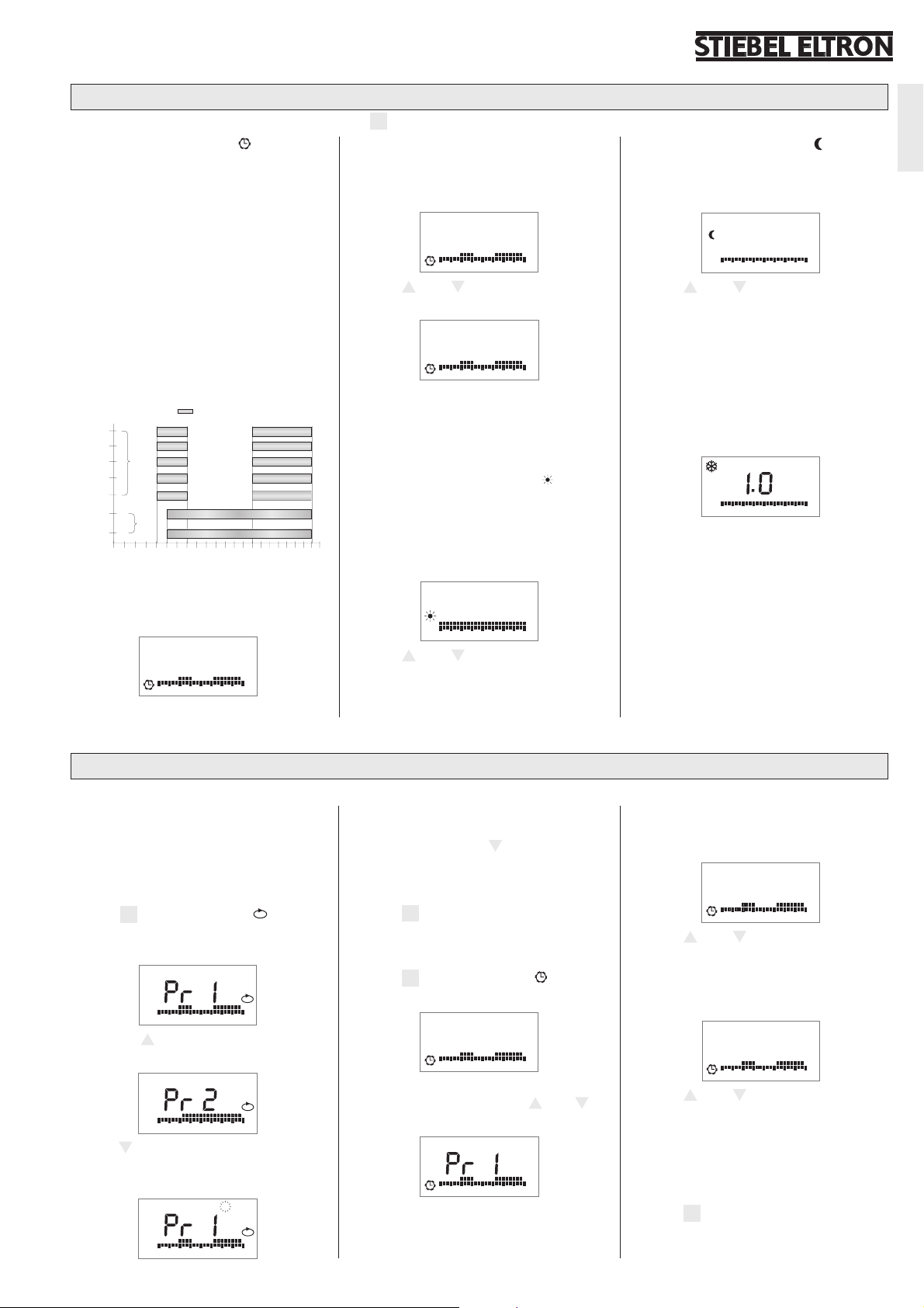
1.3.1 Uhrenprogramm
Über die eingebaute Zeitschaltuhr ist jeder
Wochentag einem Zeitprogramm zum automatischen Umschalten zwischen Komfortund Absenktemperatur zugeordnet.
Hierzu stehen 3 Zeitprogramme mit einer
festgelegten Anzahl von Schaltungen während des Tages zur Verfügung, deren Schaltzeiten individuell eingestellt werden können:
Programm 1 (P1): 2 Schaltungen
Programm 2 (P2): 1 Schaltung
Programm 3 (P3): 3 Schaltungen
Werkseitig sind folgende Schaltzeiten pro
Woche eingestellt (Wechsel zwischen Komfort-/Absenktemperatur):
Komforttemperatur
00
Mo
2
Di
3
Mi
4
Do
5
Fr
Wochentag
6
Sa
7
So
6
9
S1 E1 S2 E2
S1 E1 S2 E2
P1
S1 E1 S2 E2
S1 E1 S2 E2
00
S1
7
P2
S1
3 9 15 21
6
12 18 24
Uhrzeit
00
S1 E1 S2 E2
1
Nach dem Anwählen des Uhrenprogrammes
schaltet der Regler automatisch in das zum
aktuellen Wochentag eingestellte Programm.
1
S
1
2.5
0
6 12 18 24
00
16
23
23
P
1
Partyfunktion
Kurzzeitige Änderung der Solltemperatur
innerhalb des Uhrenprogramms bis zur
nächsten Schaltzeit.
1
1.8
0
6 12 18 24
⇒ Taste + oder
–
drücken, um Temperatur
kurzzeitig zu verändern;
1
2.2
0
6 12 18 24
⇒ Taste OK zum Bestätigen drücken. Das
Uhrenschaltprogramm ist jetzt bis zur
00
nächsten Schaltzeit mit geänderter Temperatur gültig.
1.3.2 Komforttemperatur
Hier wird die während der Hauptnutzungs-
00
E1
zeit bevorzugte Bodentemperatur eingestellt.
Der Regler hält in dieser Betriebsart durch
E1
intermittierendes Heizen die Bodentemperatur auf den eingestellten Wert.
1
2.5
0
6 12 18 24
⇒ Taste + oder
verändern. Mit Taste OK bestätigen, sonst
wird nach 20 Sekunden der bisherige
Wert wieder gültig.
–
drücken um Sollwert zu
1.3.3 Absenktemperatur
Hier sollte gegenüber der Komforttemperatur ein reduzierter Wert, z. B. während der Nachtzeit, eingestellt werden.
P
1
⇒ Taste + oder
verändern. Mit Taste OK bestätigen, sonst
wird nach 20 Sekunden der bisherige
P
1
Wert wieder gültig.
1.3.4 Frostschutz !
Nicht veränderbarer Sollwert (Anzeige 1.0),
wird bei einer Bodentemperatur von ca.
10 °C aktiv. Alle Anzeigen außer Frostschutzsymbol gehen nach ca. 20 Sekunden aus.
1
.
8
1
0
6 12 18 24
–
drücken um Sollwert zu
1
0
6 12 18 24
Deutsch
1.4 Uhrenprogramm verändern
Die Schaltzeiten des Uhrenprogrammes können den jeweiligen Wünschen des Benutzers angepasst werden.
Tagesprogramm zuordnen
Jedem Wochentag muss ein Programm zugeordnet werden, es gibt keinen Tag ohne Programmzuweisung. Um einen Tag aus einem
Programm zu entfernen, muss dieser Tag einem anderen Programm zugeordnet werden.
⇒ Taste
⇒ Mit Taste + zwischen den Programmen
⇒ Taste
M drücken bis Symbol P, Pr 1
(Programm 1) und die dem Programm
zugeordneten Tage angezeigt werden;
1
2 3 4 5
P
0
6 12 18 24
(Pr 2, Pr 3, Pr 1, . . .) wechseln;
6
7
P
0
6 12 18 24
–
drücken, um die dem angewählten
⇒ Taste OK drücken, um den angewählten
Tag dem angewählten Programm hinzuzufügen, oder mit Taste
–
zum nächsten
noch nicht zugewiesenen Tag wechseln;
⇒ Schritte wie beschrieben wiederholen, bis
alle Tage wie gewünscht zugeordnet sind;
⇒ Taste
M zum beenden drücken – Anzeige
wechselt zum Frostschutzprogramm.
Programmschaltzeiten
⇒ Taste M drücken bis Symbol angezeigt
wird;
1
S
1
2.5
0
6 12 18 24
⇒ Taste OK drücken, um in den Programmier-
modus zu wechseln, mit Taste
zu ändernde Schaltprogramm auswählen;
P
1
+ oder
–
das
Programm nicht zugewiesenen Tage blinkend anzuzeigen;
1
2 3 4 5 6
P
0
6 12 18 24
0
6 12 18 24
⇒ Taste OK drücken um zur 1. Startzeit (S1)
des ausgewählten Programms zu wechseln;
S
0
⇒ Taste + oder
1
06.00
6 12 18 24
–
zum einstellen der Start-
P
1
zeit (15min-Schritte) drücken;
⇒ Taste OK drücken um zur 1. Endzeit (E1)
des ausgewählten Programms zu wechseln;
E
0
⇒ Taste + oder
1
09.00
6 12 18 24
–
zum einstellen der End-
P
1
zeit (15min-Schritte) drücken;
⇒ Taste OK drücken um zur 2. Startzeit (S2)
des ausgewählten Programms zu wechseln;
⇒ Schritte wie beschrieben wiederholen, bis
alle Start- und Endzeiten wie gewünscht
zugeordnet sind,
⇒ Taste
M zum beenden des Einstell-
programms drücken und zum Uhrenprogramm zurückzukehren.
3
Page 4
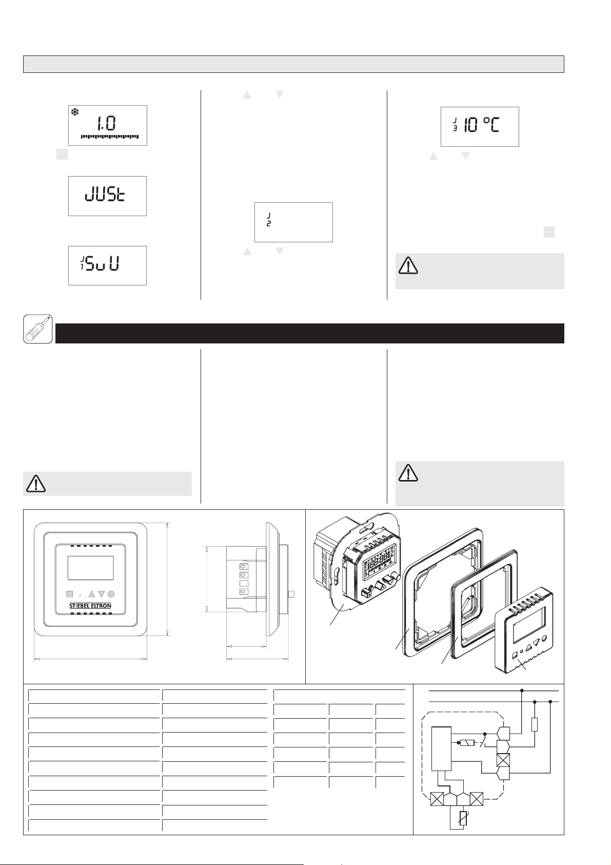
1.5 Justage (kann nur im Frostschutzbetrieb eingestellt werden)
1
6 12 18 24
0
Individuelle Einstellungen von Betriebsparametern, die auch bei Netzausfall gespeichert bleiben.
⇒ Betriebsart Frostschutz ! wählen;
⇒ Taste + oder
–
drücken, um Anzeigen-
art auszuwählen
S = Sollwert
U = Uhrzeit
SuU = Sollwert und Uhrzeit alle 5
⇒ Taste M und OK gleichzeitig 3 Sekunden
drücken bis „Just“ angezeigt wird;
⇒ Taste OK zum bestätigen und wechseln
zur nächsten Justageeinstellung drücken.
Sekunden abwechselnd;
Maximale Bodentemperatur
40 °c
Anzeigeneinstellung
⇒ Taste + oder
mal einstellbare Bodentemperatur einzustellen;
⇒ Taste OK zum bestätigen und wechseln
zur nächsten Justageeinstellung drücken.
2. Montageanweisung für den Fachmann
–
drücken, um die maxi-
Minimale Bodentemperatur
⇒ Taste + oder
einstellbare Bodentemperatur einzustellen
(Differenz zwischen min. und max. Bodentemperatur mindestens 5 °C, bei Unterschreitung wird Maximalwert automatisch
angepasst;
⇒ Taste OK drücken, um zur Anzeigenein-
stellung zurück zu kehren oder Taste
zum beenden des Justagemodus drücken.
Die minimale Bodentemperatur hat
keinen Einfluss auf die Betriebsart
„Frostschutz“.
–
drücken, um die minimal
M
Alle elektrischen Anschluss- und Installationsarbeiten sind nach den VDE-Bestimmungen
(DIN VDE 0100 T520 A3), den Vorschriften
des zuständigen EVU’s sowie den entsprechenden nationalen und regionalen Vorschriften auszuführen.
2.1 Montage Temperaturfühler
Der Temperaturfühler ist vor dem Aufbringen
des Fußboden-Oberbelages in einem Leerrohr oberflächenbündig im Untergrund (z. B.
Estrich) zu versenken; vgl. Gebrauchs- und
Montageanweisung Temperiermatte.
Installation der Schalterdose in Räumen mit
Badewanne und/oder Dusche nur außerhalb
der Schutzbereiche 1 und 2.
Bei Unterbrechung oder eines Kurzschlusses
der Fühlerleitung wird die Heizung abgeschaltet.
Im Fehlerfall kann Netzspannung an
der Fühlerleitung liegen!
2.2 Montage Temperaturregler
Der Temperaturregler ist in eine handelsübliche UP-Schalterdosen für Geräte-Ø 55 mm
einzusetzen.
Zum Einsetzen des Temperaturreglers ist wie
folgt vorzugehen:
– Kompletten Wechselrahmen (7-9) ab-
–
M
OK
+
81,5
47
81,5
Typ RTF-Z
Schaltleistung ~ 12(2) A 230 V
H x B x T 81,5 x 81,5 x 44,5 mm
Einstellbereich ca. 10 ºC . . . 50 ºC
Schaltdifferenz 1 K
Schutzklasse ΙΙ
Schutzart IP 30
Länge Temperaturfühler (DIN 44574) 4 m
Gangreserve 4 Tage, nach 1h Betriebszeit
Approbationen siehe Leistungsschild
4
28,5
10
44,5
8968.01
Fühlerkennwerte
Temperatur R [kOhm] U [V]
10 °C 3,66 2,49
20 °C 2,43 2,22
30 °C 1,65 1,92
40 °C 1,15 1,63
50 °C 0,82 1,35
ziehen, hierzu oben und unten am Schalterrahmen greifen;
– Elektrischen Anschluss nach unten abgebil-
detem Schaltbild oder dem Aufdruck auf
der Rückseite der Reglerkappe vornehmen;
– Temperaturregler (10) in Schalterdose ein-
setzen und mit dieser verschrauben;
– Gehäusedeckel (7), Zwischenrahmen (8)
sowie gegebenenfalls auch den Schalterrahmen (9) wieder aufsetzen;
Montage- und Gebrauchsanweisung
der Fußbodentemperierung, an die
der Raumtemperaturregler angeschlossen
werden soll, ist zu beachten.
9
8
L
N
RTF-Z
L
LH
Elektronik
N
FF
8969.01
7
8970.01
Page 5

6
931521
S1
Mo-Fr
Sa-Su
S1
E1
E1
S2
S3
E2
E3
E1
E2
S1
S2
P1
P2
P3
12 18 24
time
comfort temperature
otherwise Off-peak temperature
programs
6
00
6
00
12
00
9
00
9
00
14
00
16
00
17
00
23
00
23
00
7
00
23
00
P
2
S
1
1. Operating instructions for the user and the qualified installer
6121824
0
8
8
8
8
The RTF-Z with digital weekly timer serves
for individual control of the heat emission of
floor heating units. For this, a choice can be
made between four operating modes (timer
program, comfort temperature, off-peak
temperature, and frost protection).
–
M
OK
+
12 34 5 6
1 Mode - select an operating mode or
function by repeated pressing
2 Reset - restore the factory setting.
Briefly depress the flush-fitting pushbutton with a non-conductive blunt object.
3 Increase the set value
4 Decrease the set value
5 Confirm the set value
6 Display
After connecting to the mains supply until
setting the time, the thermostat automatically
switches to the „comfort temperature“
operating mode, and regulates the floor
heating unit to the temperature value set at
the factory. After setting the clock, the
thermostat then switches to the „timer pro-
Displays
Start / end time in the timer program
S1 1st start time E1 1st end time
S2 2nd start time E2 2nd end time
S3 3rd start time E3 3rd end time
Operating modes
! Frost protection
Off-peak temperature
Comfort temperaure
Timer program
8966.01
Value indicator
Setpoint floor temperature
(Guide figure, e.g. 2.5 = approx.
25 °C) or time
1 2 3 4 5 6
S
1
0
gram“ operating mode.
Heating up of the floor heating unit is identified
by the function symbol „heating operation“.
It is possible to switch off the heating operation
by changing to the „Frost protection!“
operating mode.
Days of the week
1-5 Monday - Friday
6+7 Saturday + Sunday
7
P
2.5
6 12 18 24
Time segment timer
2
Comfor t temperature
Off-peak temperature
Functions
Heating operating
Time
P
P
8967.01
Timer programs
P1 Program 1
P2 Program 2
P3 Program 3
Program selection
DeutschEnglish
Factory settings
1.1 First start-up
After connecting to the mains supply, the following displays appear:
for approx. 5 seconds . . . . . . then alternately probe defective or not connected
8
0
1.2 Setting the time and day of the week
Press push-button M until the function symbol is displayed.
Hour Push-
Floor temperatures operating modes
Guide figure °C
Frost protection 1.0
Off-peak temperature 1.8
Comfort temperature 2.5
Temperature setting limits
Max. Floor temperature 4.0
Min. Floor temperature 1.0
1 2 3 4 5 6
7
^ approx. 10
=
^ approx. 18
=
^ approx. 25
=
^ approx. 40
=
^ approx. 10
=
8
P
8
88:88
6 12 18 24
00:00
8
0
button
–
+ or
OK
2.5
6 12 18 24
Minutes
Timer program switching times
00:00
0
6 12 18 24
00
:
00
Pushbutton
+ or
OK
or
Day of the week
1
–
Pushbutton
+ or
OK
–
5
Page 6

1.3 Operating modes
P
1
S
1
P
1
P
1
6
6 12 18 24
0
7
P
P
1
S
1
P
1
S
1
P
1
E
1
To call up the desired operating mode, press push-button M until the respective symbol appears in the display.
1.3.1 Timer program
With the built-in timer, each weekday is
allocated to a time program for automatic
changeover between comfort and off-peak
temperature. Three time programs are
available with a specified number of switching
operations during the day, the switching
times of which can be individually set:
Program 1 (P1): 2 switching operations
Program 2 (P2): 1 switching operation
Program 3 (P3): 3 switching operations
The following switching times are set at the
factory for each week (changing between
comfort and off-peak temperature):
Comfort temperature
00
00
S1 E1 S2 E2
1
day of the week
Mo
2
Tu
3
We
4
Th
5
Fr
6
Sa
7
Su
6
9
S1 E1 S2 E2
S1 E1 S2 E2
P1
S1 E1 S2 E2
S1 E1 S2 E2
00
S1
7
P2
S1
3 9 15 21
6
12 18 24
time
After selecting the timer program, the
thermostat automatically switches to the
program set on the current day of the week.
1
S
1
2.5
0
6 12 18 24
00
16
23
23
P
1
Party function
Short-term change to the setpoint
temperature within the timer program up
until the next switching time.
1
1.8
0
6 12 18 24
⇒ Press + or
–
push-button to make a
short-term temperature change;
1
2.2
0
6 12 18 24
⇒ Press OK push-button to confirm. The
00
timer switching program now adopts the
change temperature until the next
switching time.
1.3.2 Comfort temperature
00
E1
Here, the preferred floor temperature during
the main period of use is set. In this
E1
operating mode, the thermostat maintains
the set value by intermittent operation of the
floor temperature heating.
1
2.5
0
6 12 18 24
⇒ Press the + or
the setpoint value. Confirm by pressing
the OK push-button, otherwise the
previously set value will be restored after
20 seconds.
–
push-button to change
1.3.3 Off-peak temperature
In comparison to the comfort temperature, a
reduced value is set, for example during the
night-time hours.
P
1
⇒ Press the + or
the setpoint value. Confirm by pressing
the OK push-button, otherwise the
P
1
previously set value will be restored after
20 seconds.
1.3.4 Frost protection !
Non-changeable setpoint value (dispaly 1.0),
which is activated at a floor temperature of
approximately 10 °C. All displays except the
frost protection symbol are extinguished
after approximately 20 seconds.
1
.
8
1
0
6 12 18 24
–
push-button to change
1
0
6 12 18 24
1.4 Changing the timer program
The switching times of the timer program can be adapted to the prevailing wishes of the user.
Allocating the daily program
A program must be allocated to each day of
the week, there is no day which doesn’t have
a program allocation. To remove a day from a
program, the day in question must be
allocated to another program.
⇒ Press push-button M until the P, Pr 1
(Program 1) symbol and the days
allocated to the program are displayed;
1
2 3 4 5
P
0
6 12 18 24
⇒ Switch between the programs (Pr 2, Pr 3,
Pr 1, . . .) using the
⇒ Press the
–
not allocated to the selected program, in
flashing mode;
6
+ push-button;
push-button, to display the days
1
2 3 4 5 6
P
0
6 12 18 24
⇒ Press the OK push-button to add the
selected day to the selected program, or
switch to the next as yet unallocated day
using the
–
push-button;
⇒ Repeat steps as described, until all days
have been allocated as desired;
⇒ Press push-button
M to terminate the
process – the display changes to the frost
protection symbol.
Program switching times
⇒ Press push-button M until the symbol
is displayed;
1
S
1
2.5
0
6 12 18 24
⇒ Press the OK push-button to switch to
the programming mode, and select the
switching program to the changed using
+ or
–
push-button;
0
6 12 18 24
the
P
1
⇒ Press the OK push-button to switch to
the 1st start time (S1) of the selected
program;
S
1
06.00
0
⇒ Press the + or
6 12 18 24
–
push-button to set the
P
1
start time (15 minute steps);
⇒ Press the OK push-button to switch to the
1st end time (E1) of the selected program;
E
1
09.00
0
⇒ Press the + or
6 12 18 24
–
push-button to set the
P
1
end time (15 minute steps);
⇒ Press the OK push-button to switch to
the 2nd start time (S2) of the selected
program;
⇒ Repeat steps as described, until all start
and end times have been allocated as
desired,
⇒ Press push-button
M to terminate the
setting program and to return to the
timer program.
Page 7

1.5 Adjsutment (can only be set in frost protection mode)
Individual settings of operating parameters, which remain stored even in the event of a power failure.
⇒ Select the frost protection ! operating
mode;
1
⇒ Press the + or
the type of display
S = setpoint value
U = time
–
push-button to select
SuU = setpoint value and time
0
6 12 18 24
⇒ Simultaneously press M and OK for 3
seconds, until „Just“ is displayed;
⇒ Press the OK push-button to confirm and
switch to the next adjustment setting.
alternating every 5 seconds;
Maximum floor temperature
40 °c
Display setting
2. Installation instructions for the qualified installer
⇒ Press the + or
maximum adjustable floor temperature;
⇒ Press the OK push-button to confirm and
switch to the next adjsutment setting.
–
push-button to set the
Minimum floor temperature
⇒ Press the + or
minimum adjustable floor temperature
(difference between the minimum and
maximum floor temperatures at least
5 °C, if this figure is fallen shor t of the
maximum value is automatically adjusted);
⇒ Press the OK push-button to return to
the display setting or press push-button
M to terminate the adjustment mode.
The minimum floor temperature
does not have any affect on the
„Frost protection“ operating mode.
–
push-button to set the
English
All electrical connection and installation work
must be carried out in accordance with the
VDE (Association of German Electrical
Engineers) instructions (DIN VDE 0100 T520
A3), the regulations of the responsible
electricity supply companies, and the relevant
national and regional regulations.
2.1 Installing the temperature probe
Prior to fitting the top covering of the floor, the
temperature probe is to be let into an empty
tube flush with the surface in the foundation
flooring (for example the screed flooring);
see operating and installation instructions for
temperature controlled floor mat.
Installation of the switch box in rooms with a
bath and/or a shower only outside zones of
protection 1 and 2.
In the event of interruption or a shor t circuit
of the probe line, the heating is switched off.
In the event of a defect the probe
line may carry mains voltage!
–
M
OK
+
81,5
2.2 Installing the thermostat
The thermostat is to be inserted into a
standard commercial UP switch box for unit
diameters of 55 mm.
The thermostat is to be inserted as follows:
– Pull off the complete changeable frame (7-
9), to do this grasp the switch frame at the
47
28,5
81,5
Type RTF-Z
Switching capacity ~ 12(2) A 230 V
H x W x D 81,5 x 81,5 x 44,5 mm
Range of adjustment ca. 10 ºC . . . 50 ºC
Switching difference 1 K
Protection class ΙΙ
Protection mode IP 30
Length of temperature probe (DIN 44574) 4 m
Power reserve 4 days, after 1h of operation
Approvals see rating plate
10
44,5
8968.01
Sensor characteristics value
Temperature R [kOhm] U [V]
10 °C 3,66 2,49
20 °C 2,43 2,22
30 °C 1,65 1,92
40 °C 1,15 1,63
50 °C 0,82 1,35
top and bottom;
– Carry out the electrical connection in
accordance with the connection diagram
illustrated below or the printed instructions
on the back of the thermostat cover;
– Insert the thermostat (10) into the switch
box and screw together;
– Replace the casing cover (7), the inter-
mediate frame (8) and, if appropriate, the
switch frame (9) in addition.
The installation and operating
instructions for the floor heating unit,
to which the room thermostat should be
connected, are to be observed.
9
8
L
N
RTF-Z
L
LH
Elektronik
N
FF
8969.01
7
8970.01
7
Page 8

P
2
S
1
6
931521
S1
понедельник -пятница
суббота -воскресенье
S1
E1
E1
S2
S3
E2
E3
E1
E2
S1
S2
P1
P2
P3
12 18 24
время суток
Комфортная температурав
ином случае Пониженная температура
6
00
6
00
12
00
9
00
9
00
14
00
16
00
17
00
23
00
23
00
7
00
23
00
программа
1. Инструкция по эксплуатации для специалиста и пользователя
6121824
0
8
8
8
8
8
8
8
8
RTF-Z – регулятор с цифровым
недельным таймером предназначен для
регулировки температуры пола с
устанавливаемым температурным
режимом. Возможно выбрать любой из 4
режимов работы (почасовая программа,
температура комфорта, пониженная
температура, защита от замерзания).
–
M
12 4 5 6
1 M - выбор режима работы или функции
путем многократного нажатия
2 Reset – восстановление заводской
настройки. Нажать на утопленную
клавишу тупым не проводящим ток
предметом
3 увеличение настраиваемого значения
4 уменьшение настраиваемого значения
5 подтверждение настраиваемого
значения
6 дисплей
3
OK
+
После подключения к электрической сети
до тех пор, пока не установлено текущее
время, регулятор автоматически
включается в режим «комфортная
температура» и подогревает пол до
заданной температуры, установленной
заводом-изготовителем. После
установки текущего времени регулятор
Индикация на дисплее
Время запуска/время завершения в подпрограмме
S1 1-е время включения E1 1-е время выключения
S2 2-е время включения E2 2-е время выключения
S3 3-е время включения E3 3-е время выключения
Режимы работы
! Защита от замерзания
Пониженная
температура
Комфортная
температура
8966.01
Программа настройки
часов
Индикация значений
Заданное значение
температуры поверхности
пола (условное обозначение;
например, 2.5 = примерно
25°С) или время
1 2 3 4 5 6
S
1
2.5
0
6 12 18 24
Сегменты таймера
Комфортная температура
Пониженная температура
переключается в режим «почасовая
программа».
Текущий нагрев пола можно определить
по функциональному символу «режим
подогрева».
Отключение режима подогрева
возможно путем переключения в режим
«защита от замерзания».
Дни недели
1-5 понедельник – пятница
6+7 суббота + воскресенье
7
P
P
2
Подпрограммы
Р1 программа 1
Р2 программа 2
Р3 программа 3
Функции (см.
символы)
Нагрев
Текущее время
P
8967.01
Выбор программ
Заводские настройки
Режимы работы
Условное
обозначение °C
Защита от замерзания 1.0 около 10
Пониженная температура 1.8 около 18
Комфортная температура 2.5 около 25
Пределы настройки температуры
Макс. температура поверхности пола 4.0 около 40
Мин. температура поверхности пола 1.0 около 10
Время переключения в подпрограммах (см.рис.)
1.1 Первоначальный ввод в эксплуатацию
После подключения к электрической сети появляется следующая индикация:
примерно в течение 5 сек... ... затем попеременно
1 2 3 4 5 6
1 2 3 4 5 6
8
8
8
8
88:88
88:88
0
0
6 12 18 24
8
6 12 18 24
7
7
8
8
P
P
8
8
2.5
2.5
0
0
6 12 18 24
6 12 18 24
00:00
0
6 12 18 24
датчик неисправен или не подключен
èëè
Page 9

P
1
S
1
P
1
P
1
1.2 Настройка времени и дня недели
Удерживать нажатой клавишу M до тех пор, пока не появится символ функции .
÷àñû клавиши
+ èëè
00:00
00:00
OK
минуты
–
00
00
:
клавиши
+ èëè
OK
–
день недели
1
клавиши
+ èëè
OK
1.3 Режимы работы
Для вызова нужной функции удерживать нажатой клавишу M до тех пор, пока на дисплее не появится соответствующий символ.
1.3.1 Программа настройки
часов
Через встроенную программу таймера
каждый день недели присвоен
программе настройки времени для
автоматического переключения между
программой комфорта и температурой
охлаждения.
Для этого в распоряжении имеется 3
программы настройки времени с
заданным количеством переключений
в течение суток, время переключения в
которых можно настроить индивидуально:
Программа 1 (Р1): 2 переключения
Программа 2 (Р2): 1 переключение
Программа 3 (Р3): 3 переключения
На заводе настроено следующее время
переключения в течение недели
(переключение между температурой
комфорта и охлаждения):
Температура комфорта
00
00
1
2
3
4
5
День недели
6
7
После выбора программы настройки
часов регулятор автоматически
переключается на программу,
настроенную на текущий день недели.
S1 E1 S2 E2
6
9
S1 E1 S2 E2
S1 E1 S2 E2
P1
S1 E1 S2 E2
S1 E1 S2 E2
00
S1
7
P2
S1
3 9 15 21
6
S
0
12 18 24
Время
1
1
2.5
6 12 18 24
00
16
P
1
00
23
00
23
Функция «Party»
Кратковременное изменение заданной
температуры внутри программы
настройки часов до следующего
времени переключения.
1
1.8
0
6 12 18 24
⇒ Нажать клавишу + èëè
кратковременного изменения
температуры;
1
2.2
0
6 12 18 24
⇒ Нажать клавишу «ОК» для
подтверждения выбора. Программа
таймера будет выполняться с
измененной температурой до
следующего времени переключения.
1.3.2 Комфортная температура
Здесь настраивается предпочитаемая
температура пола на основной период
использования. В этом режиме
регулятор поддерживает температуру
E1
пола на настроенном значении путем
постоянного подогрева.
E1
1
2.5
0
6 12 18 24
⇒ Для изменения заданного значения
нажать клавишу + или
клавишу «ОК» для подтверждения
выбора, иначе в течение 20 сек. будет
восстановлено предыдущее значение.
P
1
–
äëÿ
P
1
–
.Нажать
1.3.3 Пониженная температура
По отношению к комфортной температуре
здесь должно быть настроено меньшее
значение, например, на ночное время.
1
.
8
1
0
6 12 18 24
⇒ Для изменения заданного значения
нажать клавишу + или
клавишу «ОК» для подтверждения
выбора, иначе в течение 20 сек. будет
восстановлено предыдущее значение.
–
.Нажать
1.3.4 Защита от замерзания !
Неизменяемое заданное значение
(индикация 1.0) активизируется при
температуре поверхности пола 10 С.
Вся индикация, кроме символа защиты
от замерзания, исчезает с дисплея
примерно через 20 сек.
1
0
6 12 18 24
–
Pyccêèé
9
Page 10

1
6 12 18 24
0
1.4 Изменение программы настройки часов
6
6 12 18 24
0
7
P
P
1
S
1
P
1
S
1
P
1
E
1
Время переключения программы настройки часов можно изменить в соответствии с пожеланиями заказчика.
Присвоение суточной программы
Каждому дню недели должна быть
присвоена программа, не существует
дней без присвоения им программ.
Чтобы удалить день из программы, этот
день должен быть присвоен другой
программе.
⇒ Удерживать нажатой клавишу M äî
тех пор, пока на дисплее не появится
символ
P, Pr 1 ((программа 1) и
дни, которые присвоены программе;
1
2 3 4 5
P
0
6 12 18 24
⇒ С помощью клавиши + произвести
переключение между программами
(Pr2, Pr3, Pr1...);
⇒ Нажать клавишу
–
, чтобы замигали
дни, не присваиваемые выбранной
программе;
1
2 3 4 5 6
P
0
6 12 18 24
⇒ Нажать клавишу «ОК», чтобы
выбранный день добавить в выбранную
программу, или с помощью клавиши
–
перейти к следующему еще не
присвоенному программе дню;
⇒ Повторять описанные шаги до тех
пор, пока все дни не будут присвоены
программам желаемым образом;
⇒ В завершении нажать клавишу M -
индикация переключится на
программу защиты от замерзания.
Время переключения программ
⇒ Удерживать нажатой клавишу M äî
тех пор, пока на дисплее не появится
символ ¹;
1
S
1
2.5
0
6 12 18 24
P
1
⇒ Нажать клавишу «ОК», чтобы перейти
в режим программирования, с
помощью клавиш + èëè
–
выбрать
программу переключения, которую
нужно изменить;
0
6 12 18 24
⇒ Нажать клавишу «ОК», чтобы
перейти к первому времени запуска
(S1) выбранной программы;
S
1
06.00
0
6 12 18 24
⇒ Нажать клавиши + èëè
настройки времени запуска (шаги по
15 мин.);
⇒ Нажать клавишу «ОК», чтобы перейти
к первому времени завершения (Е1 )
выбранной программы;
E
1
09.00
0
6 12 18 24
⇒ Нажать клавиши + èëè
настройки времени завершения
(шаги по 15 мин.);
⇒ Нажать клавишу «ОК», чтобы перейти
ко второму времени завершения (S2 )
выбранной программы;
⇒ Повторять описанные шаги до тех
пор, пока все время запуска и
завершения не будет присвоено
желаемым образом;
⇒ Нажать клавишу M для завершения
программы настройки и для
возвращения к программе
настройки времени.
P
1
P
1
–
äëÿ
–
äëÿ
1.5 Настройка (может настраиваться только в режиме защиты от замерзания)
Индивидуальные настройки режимных параметров, которые сохраняются и при отключении эл. сети.
⇒ Выбрать режим защиты от
замерзания ! ;
⇒ Одновременно держать нажатыми в
течение 3 сек. клавиши M и «ОК»,
пока не появится индикация «Just»;
Настройка индикации
⇒ Нажать клавиши + èëè
выбрать вид индикации
S= заданное значение
U= время
SuU = заданное значение и время
попеременно каждые 5 сек.;
⇒ Нажать клавишу «ОК» для
подтверждения выбора и перехода к
следующей настройке юстировки.
Максимальная температура
поверхности пола
40 °c
⇒ Нажать клавиши + èëè
настроить максимально настраиваемую
температуру поверхности пола;
⇒ Нажать клавишу «ОК» для
подтверждения выбора и перехода к
следующей настройке юстировки.
–
, чтобы
–
, чтобы
Минимальная температура
поверхности пола
⇒ Нажать клавиши + èëè
настроить минимально настраиваемую
температуру поверхности пола
(разница между макс. и мин.
температурой поверхности пола
должна составлять мин. 5°С, если
оно будет меньше, то максимальное
значение будет автоматически
подстраиваться);
⇒ Нажать клавишу «ОК» для возврата к
настройке индикации или нажать
клавишу
юстировки.
режим «Защита от замерзания».
M для выхода из режима
Минимальная температура
поверхности пола не влияет на
–
, чтобы
10
Page 11

2. Инструкция по монтажу для специалиста
Все работы по электрическому
подключению и установке следует
проводить согласно определениям
Союза немецких электротехников
(DIN VDE 0100 T520 A3), правилам
электроснабжающего предприятия, а
также национальным и региональным
правилам.
Установка регулятора в помещениях с
ванной и/или душем запрещена в зонах
безопасности 1 и 2!
При разрыве или коротком замыкании
провода температурного датчика
нагрев отключается.
В повреждении регулятора
провод температурного датчика
может оказаться под сетевым
напряжением.
2.1 Монтаж температурного
датчика
Перед нанесением верхнего слоя
полового покрытия необходимо
уложить полую трубку для
температурного датчика в основу таким
образом, чтобы поверхность основы
осталась плоской; см. инструкцию по
эксплуатации и монтажу для
нагревательных матов.
С помощью гибкого провода
стандартный провод температурного
датчика можно удлинить до 50 м.
2.2 Монтаж регулятора
температуры
Регулятор температуры необходимо
устанавливать в стандартной UP-коробке
для выключателя диаметром 55 мм.
Для установки регулятора температуры
необходимо выполнить следующие
действия:
– полностью снять съемные рамку (7-9;
– произвести электрическое
подключение согласно схеме,
указанной ниже или на обратной
стороне крышки регулятора;
– регулятор температуры (10)
поместить в коробку для установки
выключателя и зафиксировать
винтовым соединением;
– установить крышку корпуса (7),
промежуточную рамку (8 и при
необходимости рамку выключателя
(9) на место.
Необходимо учитывать
требования инструкции по
эксплуатации для нагревательных
матов, к которым должен быть
подключен регулятор температуры.
Pyccêèé
L
N
M
81,5
RTF-Z
Elektronik
FF
–
OK
+
81,5
47
10
28,5
LH
N
44,5
Òèï RTF-Z
Коммутационная мощность ~ 12(2) A 230 V
Высота х ширина х глубина 81,5 x 81,5 x 44,5 mm
L
Диапазон настройки около 10 ºC . . . 50 ºC
Перепад температуры 1 K
Класс защиты
Вид защиты IP 30
Длина провода температурного датчика (DIN 44574) 4 m
8968.01
Запас хода 4 дня, После 1 часа работы
Сертификаты см. заводскую табличку с указанием
8970.01
Параметры датчика
Температура
R [kOhm] U [V]
10 °C 3,66 2,49
20 °C 2,43 2,22
30 °C 1,65 1,92
40 °C 1,15 1,63
50 °C 0,82 1,35
9
8
ΙΙ
номинальных данных
8969.01
7
OSKO-Service Moskau:
129090 Россия, г. Москва, ул. Троицкая, д.9, к.1
тел.: +7 (095) 933-8774 факс: +7 (095) 933-8775
OSKO-Service St.-Petersburg:
197022 Россия, г. С.-Петербург, Каменноостровский пр., д. 50
тел.: +7 (812) 234-9369, 327-5252 факс: +7 (812) 325-1346
11
Page 12

Adressen und Kontakte www.stiebel-eltron.com
Zentrale Holzminden
Stiebel Eltron GmbH & Co. KG
Dr.-Stiebel-Str. 37603 Holzminden
Telefon 0 55 31 / 7 02-0
Fax Zentrale 0 55 31 / 7 02-4 80
E-Mail info@stiebel-eltron.com
Internet www.stiebel-eltron.com
Stiebel Eltron International GmbH
Dr.-Stiebel-Str. 37603 Holzminden
Telefon 0 55 31 / 7 02-0
Fax 05531/702-479
E-Mail info@stiebel-eltron.com
Internet www.stiebel-eltron.com
Unseren zentralen Service
erreichen Sie unter 0 180 3...
... in der Zeit von:
Montag bis Donnerstag 715 bis 1800 Uhr
Freitag 715 bis 1700 Uhr
Info-Center
allgemeine Information
und technische Auskunft
Telefon 0 180 3 - 70 20 10
Telefax 0 180 3 / 70 20 15
E-Mail: info-center@stiebel-eltron.com
0 180 3 -
STI EBEL
7843235
Kundendienst
Telefon 0 180 3 - 70 20 20
Telefax 0 180 3 / 70 20 25
E-Mail: kundendienst@stiebel-eltron.com
Ersatzteil-Verkauf
Telefon 0 180 3 - 70 20 30
Telefax 0 180 3 / 70 20 35
E-Mail: ersatzteile@stiebel-eltron.com
0,09 /min (Stand: 12/02)
Gedruckt auf
100% Recycling-Papier.
Aktiv im Umweltschutz.
7851
Stiebel Eltron Vertriebszentren
Dortmund
Oespel (Indupark)
Brennaborstr. 19 44149 Dortmund
Telefon 02 31 /96 50 22-10
E-Mail: dortmund@stiebel-eltron.com
Frankfurt
Rudolf-Diesel-Str. 18 65760 Eschborn
Telefon 0 61 73/ 6 02-10
E-Mail: frankfurt@stiebel-eltron.com
Hamburg
Georg-Heyken-Straße 4a 21147 Hamburg
Telefon 0 40 / 75 20 18-10
E-Mail: hamburg@stiebel-eltron.com
Holzminden/Info-Center
Berlin/Hannover/Nürnberg
Dr.Stiebel-Straße 37603 Holzminden
Telefon 0 180 3 / 70 2010
E-Mail: info-center@stiebel-eltron.com
Köln
Ossendorf (Butzweiler Hof)
Mathias-Brüggen-Str. 132 50829 Köln
Telefon 02 21 /5 97 71-10
E-Mail: koeln@stiebel-eltron.com
Leipzig
Airport Gewerbepark/Glesien
Ikarusstr. 10 04435 Schkeuditz-Glesien
Telefon 03 4207/ 7 55-10
E-Mail: leipzig@stiebel-eltron.com
München
Hainbuchenring 4 82061 Neuried
Telefon 0 89/ 8991 56-10
E-Mail: muenchen@stiebel-eltron.com
Stuttgart
Weilimdorf
Motorstr. 39 70499 Stuttgart
Telefon 07 11/ 9 8867-10
E-Mail: stuttgart@stiebel-eltron.com
Tochtergesellschaften und Vertriebszentren Europa und Übersee
Belgique
Stiebel Eltron Sprl/Pvba
Rue Mitoyenne 897 B-4840 Welkenraedt
087-88 14 65 Fax 087-88 15 97
E-Mail stiebel@skynet.be
Internet www.stiebel-eltron.com
∨∨
∨
∨∨
C
eská republika
Stiebel Eltron spol. s r.o.
oo
o
oo
K Háju
m 946 C
∨∨
∨
∨∨
Z-15500 Praha 5-Stodulky
2-511 16 111 Fax 2-355 12 122
E-Mail info@stiebel-eltron.cz
Internet www.stiebel-eltron.cz
France
Stiebel Eltron International
Succursale Française à Metz
7-9, rue des Selliers
B.P. 85107 F-57073 Metz-Cédex
03-87-74 38 88 Fax 03-87-74 68 26
E-Mail secretcom@stiebel-eltron.fr
Internet www.stiebel-eltron.fr
Great Britain
Stiebel Eltron Ltd.
Lyveden Road
Brackmills GB-Northampton NN4 7ED
016 04-76 64 21 Fax 01604-7652 83
E-Mail info@stiebel-eltron.co.uk
Internet www.stiebel-eltron.co.uk
Magyarország
Stiebel Eltron Kft.
Pacsirtamezo´´ !u.! 41 H-1036 Budapest
012 50-60 55 Fax 013 68-80 97
E-Mail info@stiebel-eltron.hu
Internet www.stiebel-eltron.hu
Nederland
Stiebel Eltron Nederland B.V.
Daviottenweg 36
Postbus 2020 NL-5202 CA's-Hertogenbosch
073-6 23 00 00 Fax 073-6 23 11 41
E-Mail stiebel@stiebel-eltron.nl
Internet www.stiebel-eltron.nl
Österreich
Stiebel Eltron Ges.m.b.H.
Eferdinger Str. 73 A-4600 Wels
072 42-4 7367-0 Fax 072 42-4 73 67-42
E-Mail info@stiebel-eltron.at
Internet www.stiebel-eltron.at
Polska
Stiebel Eltron sp.z. o.o
ul. Instalatorów 9 PL-02-237 Warszawa
022-8 46 48 20 Fax 022-8 46 67 03
E-Mail stiebel@stiebel-eltron.com.pl
Internet www.stiebel-eltron.com.pl
Sverige
Stiebel Eltron AB
Box 206 SE-641 22 Katrineholm
0150-48 7900 Fax 0150-48 7901
E-Mail info@stiebel-eltron.se
Internet www.stiebel-eltron.se
Schweiz
Stiebel Eltron AG
Netzibodenstr. 23 c CH-4133 Pratteln
061-8 16 93 33 Fax 061-8 16 93 44
E-Mail info@stiebel-eltron.ch
Internet www.stiebel-eltron.com
Thailand
Stiebel Eltron Ltd.
469 Building 77, Bond Street
Tambon Bangpood
Ampur Pakkred Nonthaburi 11120
02-960 1602-4 Fax 02-960 1605
E-Mail stiebel@loxinfo.co.th
Internet www.stiebeleltronasia.com
USA
Stiebel Eltron Inc.
242 Suffolk Street Holyoke MA 01040
04 13-5 38-78 50 Fax 04 13-5 38-85 55
E-Mail info@stiebel-eltron-usa.com
Internet www.stiebel-eltron-usa.com
CAP 185582/33401/2/7860 · ALRE · Änderungen vorbehalten · These instructions are subject to alteration notice! · Возможны ижменения
 Loading...