

RTF-TC
RTU-TC
RTF-TC
RTU-TC
INSTRUCTIONS
• English
• Deutsch
• Français
• Suomi
• Polski
• Česky
GREEN COMFORT
Maximum comfort with low energy consumption
• Svenska
• Nederlands
• Lietuvių k.
• Italiano
• Español
• Português

ILLUSTRATIONS
Pages ....................................................................................3
INSTRUCTIONS
English .................................................................................. 7
Deutsch .............................................................................. 12
Français .............................................................................. 17
Suomi ................................................................................. 22
Polski .................................................................................. 27
Česky .................................................................................. 32
Svenska .............................................................................. 37
Nederlands ......................................................................... 42
Lietuvių k. ........................................................................... 47
Italiano ................................................................................ 52
Español ............................................................................... 57
Português ........................................................................... 62
BR1017A02
Fig. 1
BR1017A01
Fig. 2
RTF-TC
RTU-TC
BR1017A01BR1017A02
3© 2018 OJ Electronics A/S
RTF-TC / RTU-TC
BR1017A05A
653 421
N
L
Fig. 3
Fig. 4
BR1017A03A
1.5m
BR1017A03a
1
3
2
BR1017A04c
4 © 2018 OJ Electronics A/S © 2018 OJ Electronics A/S

BR1017A06
Fig. 5
Fig. 6
L
N
653 421
BR1017A05A
BR1017A05aBR1017A06
RTF-TC / RTU-TC
1
Fig. 7
Fig. 8
Fig. 9
1
2
3
4
4
BR1017A14BR1017A07
ON
BR1017A07
OFF
Manual
2
Menu
Auto
BR1017A17

RTF-TC
RTU-TC
Instruction
English
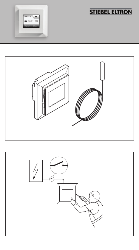
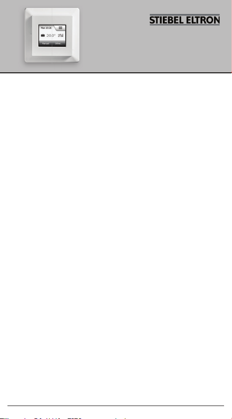
FIG. 1 - CONTENT
• Thermostat
• Sensor
The thermostat is an electronic PWM/PI thermostat for temperature
control by means of an NTC sensor located either externally or
internally within the thermostat.
The thermostat is for fl ush mounting in a wall socket. A baseplate
for wall mounting is also available.
This thermostat can be used as a controller for electric room heating
pursuant to EN50559.*
* Only valid for RTF-TC (MCD5-1999)
Product programme
RTF-TC (MCD5-1999) Clock-thermostat with two sensors:
RTU-TC (MCC5-1999) Clock-thermostat with built-in room
sensor.
FIG. 2 - WARNING – Important Safety Instructions
Disconnect the power supply before carrying out any installation or
maintenance work on this thermostat and associated components.
The thermostat and associated components should only be installed
by a competent person (i.e. a qualifi ed electrician). Electrical installation must be in accordance with appropriate statutory regulations.
fl oor sensor and built-in room sensor.
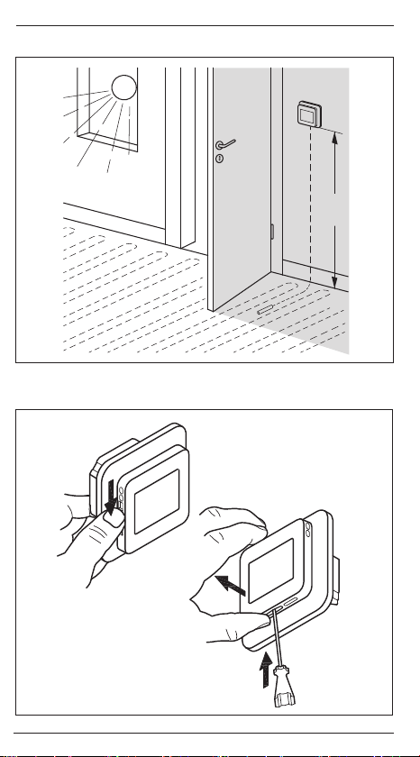
FIG. 3 - THERMOSTAT PLACEMENT
Mounting of sensor
The fl oor sensor contains a safety extra-low voltage (SELV) circuit,
allowing it to be placed as close to the fl oor surface as possible
without having to take account of the risk of shock should the sensor cable become damaged. The two wires connecting the sensor
to the mounting box must be additionally insulated, e.g. shrink fl ex.
7© 2018 OJ Electronics A/S

/ RTU-TC English
RTF-TC
To prevent loose wires in the fixed installation from coming into
contact with the terminal block for the floor sensor, they must be
restrained using cable ties.
It is strongly recommended that the cable and sensor are placed in
a non-conductive installation pipe embedded in the floor. The end
of the pipe must be sealed and the pipe placed as high as possible
in the concrete layer. The sensor cable must be led through a
separate conduit or segregated from power cables.
The floor sensor must be centred between loops of heating cable.
The sensor cable may be extended up to 100 m by means of a
separate two-core cable. Two vacant wires in a multi-core cable
used, for example, to supply current to the floor heating cable must
not be used. The switching peaks of such current supply lines may
create interference signals that prevent optimum thermostat function. If a shielded cable is used, the shield must not be connected
to earth (PE). The two-core cable must be placed in a separate
pipe or segregated from power cables in some other way.
Mounting of thermostat with built-in sensor
The room sensor is used for comfort temperature regulation in
rooms. The thermostat should be mounted on the wall approx.
1.5 m above the floor in such a way as to allow free air circulation
around it. Draughts and direct sunlight or other heat sources must
be avoided.
FIG. 4 - OPENING THE THERMOSTAT
1. Slide the power button down to O “0”.
2. Release the front cover ONLY by inserting a small screwdriver
into the slot at the centre of the bottom side of the front cover to
press and hold the catch securing the front cover.
3. Then carefully pull the front cover away, initially from the lower
part of the thermostat, then from the upper part of the thermostat.
FIG. 5 - CONNECTIONS
Connect the wires in accordance with the diagram. The wires must
be connected as follows:
Term. 1: Neutral (N)
Term. 2: Live (L)
Term. 3-4: Output, max. 16 A
Term. X: Do not connect
8 © 2018 OJ Electronics A/S © 2018 OJ Electronics A/S
RTF-TC / RTU-TC English
Term. 5-6: External floor sensor (RTF-TC Thermostats only)
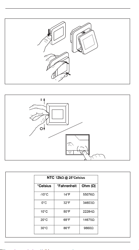
FIG. 6 + 7 - MOUNTING THE THERMOSTAT
1. Mount the thermostat in the wall socket.
2. Fit the frame and carefully press the cover onto the thermostat
- starting with the upper part of the cover, then the lower part of
the cover. Ensure that both the power slide button on the cover
and the power switch pin in the thermostat are down.
3. Click the cover into place by applying light, even pressure.
Warning! Do not apply pressure to the corners of the display
cover or to the display itself.
DO NOT open the thermostat by releasing the four fixing clips on
the back.
FIG. 8 - OPERATING THE THERMOSTAT
There is an ON/OFF switch on the left side of the thermostat: up is
ON - down is OFF.
The resistive touchscreen requires a soft tap with your fingertip to
register the touch.
Installer Wizzard:
The first time the thermostat is connected, push the power slide
button to On “I” The Installer Wizard on the touchscreen will guide
you through the set up of:
1. Region
2. Language
3. Date
4. Time
5. Floor Type
Programming
See user manual.
https://csd.stiebel-eltron.de/Montageanweisung/RTF-TC_en.pdf
/ RTU-TC English RTF-TC / RTU-TC English
RTF-TC
FIG. 9 - TROUBLESHOOTING
If the sensor is disconnected or short-circuited, the heating system
is switched o. The sensor can be checked against the resistance
table.
Error codes
E0: Internal fault. The thermostat must be replaced.
E1: Built-in sensor defective or short-circuited. Replace the ther-
mostat, or use the floor sensor only.
E2: External sensor disconnected, defective or short-circuited.
Reconnect the sensor if disconnected, or replace the sensor.
E5: Internal overheating. Inspect the installation.
CE marking
According to the following standard:
LVD/EMC: EN 60730-1
Classification
Protection from electric shock must be assured by appropriate
installation. Appropriate installation must meet the requirements of
Class II (enhanced insulation).
Environment and recycling
Please help us to protect the environment by disposing of the
packaging in accordance with national regulations for waste
processing.
Recycling of obsolete appliances
Appliances with this label must not be disposed of with
general household waste. They must be collected
separately and disposed of in compliance with local
regulations.
10 © 2018 OJ Electronics A/S © 2018 OJ Electronics A/S
RTF-TC / RTU-TC English
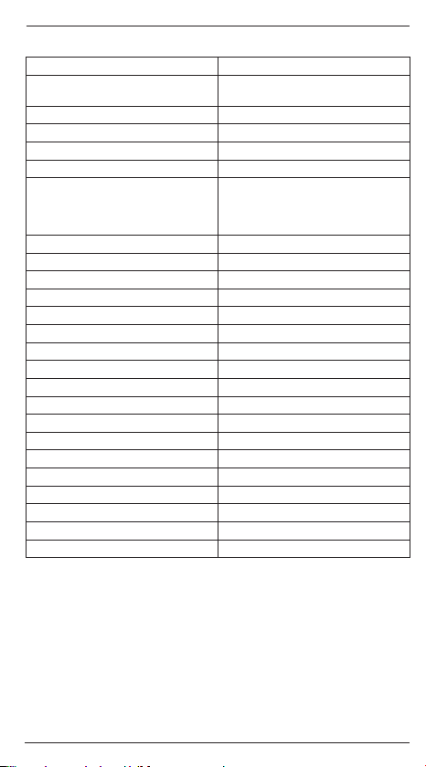
TECHNICAL SPECIFICATIONS
Purpose of control Electrical underfloor heating
Method of mounting.
Supply voltage 100-240 VAC ±10% 50/60 Hz
Max. pre-fuse 16 A
Built-in interupter 2-pole, 16 A
Enclosure rating IP 21
Wire size, terminals
ELV limits realized SELV 24 VDC
Output relay Make contact - SPST - NO
Output, load Max. 16 A / 3600 W
Control principle PWM/PI
Standby consumption ≤0.5 W
Battery backup 5 years (storage)
Battery life, typical 5 years (storage) 10 years (powered)
Dimensions MxD5: H/84, W/84, D/40 mm
Build-in depth 22mm
Weight ≤200 g
Display 176x220 pixels TFT - resistive touch
Control pollution degree 2
Overvoltage category III
Type of action 1.B
Software class A
Rated impulse voltage 4kV
Ball pressure temperature (TB) 125°C
EU registered design DM/082270
Note: At very low ambient temperatues the display may respond slowly.
Wall mounting in a socket or
mounting box
Current ≤ 13 A - 1.5 mm
wire
Current > 13 A to 16 A - 2.5 mm2,
solid core wire
2
, solid core

RTF-TC
RTU-TC
Anleitung
Deutsch
ABB. 1 – LIEFERUMFANG
• Thermostat
• Fühler
Der Thermostat ist ein elektronischer PBM/PI-Thermostat zur Temperaturregelung mittels extern angebrachtem oder im Thermostat
eingebauten NTC-Fühler.
Der Thermostat ist für Unterputzmontage in einer Wanddose
vorgesehen. Eine Grundplatte für Wandmontage ist ebenfalls
verfügbar.
Dieser Thermostat kann zur Steuerung von elektrischer Raumheizung gemäß EN50559 verwendet werden.*
*Nur gültig für RTF-TC (MCD5-1999)
Produktprogramm
RTF-TC (MCD5-1999) Uhr-Thermostat mit zwei Fühlern: Bo-
RTU-TC (MCC5-1999) Uhr-Thermostat mit eingebauter Raum-
ABB. 2 – WARNHINWEIS – Wichtige Sicherheitsanweisungen.
Vor der Ausführung von Installations- oder Instandhaltungsarbeiten an diesem Thermostat und zugehörigen Komponenten ist
die Spannungsversorgung zu unterbrechen. Der Thermostat und
zugehörige Komponenten dürfen nur von einer sachkundigen
Person (d. h. einem qualifi zierten Elektriker) installiert werden.
Die Elektroinstallation muss den entsprechenden gesetzlichen
Vorschriften entsprechen.
denfühler und eingebauter Raumfühler.
fühler.
ABB. 3 – THERMOSTAT-PLATZIERUNG
Montage des Fühlers
Der Bodenfühler ist mit einem Kleinspannungs-Sicherheitskreis
(SELV) ausgestattet, womit eine Anbringung möglichst nahe an
© 2018 OJ Electronics A/S © 2018 OJ Electronics A/S12
/ RTU-TC Deutsch
RTF-TC
der Fußbodenoberfläche ohne Risiko von Stromschlägen durch
ein eventuell schadhaft werdendes Fühlerkabel erfolgen kann. Die
beiden Leiter für den Anschluss des Fühlers im Klemmenkasten
müssen zusätzlich isoliert werden, z. B. mit Schrumpfschlauch.
Um einem Kontakt der Klemmenleiste des Bodenfühlers mit losen
Drähten der vorhandenen Installation vorzubeugen, müssen diese
mit Kabelbindern festgemacht werden.
Es empfiehlt sich, Kabel und Fühler in einem im Boden eingelassenen, nicht leitenden Installationsrohr anzubringen. Mit verschlossenem Rohrende sollte das Rohr so hoch wie möglich in der Estrichschicht eingebettet sein. Das Fühlerkabel ist in einem separaten
Rohr oder getrennt von Leistungskabeln zu verlegen.
Der Bodenfühler muss zwischen den Heizkabelschleifen zentriert
werden.
Das Fühlerkabel kann mit einem separaten Zweileiterkabel bis zu
100 m verlängert werden. Freie Leiter in einem z. B. das Bodenheizkabel mit Strom versorgenden Mehrleiterkabel dürfen nicht
verwendet werden. Die Schaltspitzen einer derartigen Stromversorgung können Interferenzen auslösen die eine optimale Thermostatfunktion behindern. Wird ein abgeschirmtes Kabel verwendet,
darf die Abschirmung nicht geerdet werden. Das Zweileiterkabel
ist in einem separaten Rohr oder getrennt von Leistungskabeln zu
verlegen.
Montage eines Thermostats mit eingebautem Fühler
Der Raumfühler wird zur Regelung der Komforttemperatur in
Räumen eingesetzt. Der Thermostat ist auf der Wand ca. 1,5 m
über dem Boden und freier Luftzirkulation um ihn gestattend zu
montieren. Zugluft und direkte Sonneneinstrahlung oder andere
Wärmequellen müssen vermieden werden.
ABB. 4 – ÖFFNEN DES THERMOSTAT GEHÄUSES
1. Den Schiebeschalter nach unten in Position Aus „0“ schieben.
2. Zum Lösen der Frontabdeckung NUR einen kleinen Schraubendreher benutzen. Diesen in den Schlitz an der Unterseite
der Frontabdeckung einstecken, nach oben drücken und die
Frontabdeckung festhalten.
3. Danach vorsichtig die Frontabdeckung entfernen, zuerst von
unten am Thermostat und dann von oben.
/ RTU-TC Deutsch
RTF-TC
ABB. 5 – ANSCHLÜSSE
Die Leiter gemäß Schaltplan anschließen. Die Leiterdrähte müssen
wie folgt angeschlossen werden:
Klemme 1: Nullleiter (N)
Klemme 2: Phase (L)
Klemme 3-4: Ausgang, max. 16A
Klemme X: Nicht benutzen
Klemme 5-6: Externer Bodenfühler (Nur gültig für RTF-TC)
ABB. 6 + 7 – MONTAGE DES THERMOSTATS
1. Den Thermostat in der Wanddose montieren.
2. Den Rahmen anpassen und den Deckel vorsichtig auf den Thermostat aufsetzen – beginnend mit dem oberen Teil des Deckels
und dann dessen unteren Teil. Bitte beachten, dass sich sowohl
der Schiebeschalter am Deckel als auch der zugehörige Stift im
Thermostat in unterster Position befinden.
3. Den Deckel mit leichtem, gleichmäßigem Druck auf dem
Gehäuse einrasten. Achtung! Nicht auf die Ecken der DisplayAbdeckung oder auf das Display drücken.
KEINESFALLS den Thermostat bei den vier Befestigungsschellen
auf der Rückseite önen.
ABB. 8 – BEDIENUNG DES THERMOSTATS
Ein EIN/AUS-Schalter befindet sich auf der linken Seite des Thermostats: Stellung oben ist EIN – Stellung unten ist AUS.
Der resistive Touchscreen erfordert ein weiches Antippen mit der
Fingerspitze um die Berührung zu registrieren.
Erste Einstellungen:
Zur ersten Inbetriebnahme des Thermostats den Betriebsschalter
in Position Ein „I“ schieben. Der Installationsassistent auf dem
Touchscreen führt Sie durch das Setup von:
1. Region
2. Sprache
3. Datum
4. Uhrzeit
5. Bodentyp
14 © 2018 OJ Electronics A/S © 2018 OJ Electronics A/S
Programmierung
Siehe Benutzerhandbuch:
https://csd.stiebel-eltron.de/Montageanweisung/RTF-TC_en.pdf
ABB. 9 - FEHLERSUCHE UND -BEHEBUNG
Bei unterbrochenem oder kurzgeschlossenem Fühler wird die Heizanlage abgeschaltet. Der Fühler lässt sich mit der Widerstandstabelle abgleichen.
Fehlercodes
E0: Interner Fehler. Der Thermostat muss ausgetauscht werden.
E1: Interner Fühler defekt oder kurzgeschlossen. Thermostat aus-
tauschen, oder nur den Bodenfühler verwenden.
E2: Externer Fühler getrennt, defekt oder kurzgeschlossen. Fühler
wenn getrennt anschließen, oder Fühler austauschen.
E5: Interne Überhitzung. Installation kontrollieren.
CE-KENNZEICHNUNG
Gemäß folgendem Standard:
NSR/EMV: EN 60730-1
Klassifikation
Schutz vor elektrischem Schlag muss durch entsprechende
Installation gewährleistet sein. Entsprechende Installation muss die
Anforderungen der Klasse II (verstärkte Isolierung) erfüllen.
Umwelt und Recycling
Bitte helfen Sie uns die Umwelt zu schützen und entsorgen Sie die
Verpackung gemäß den nationalen Vorschriften für Abfallverwertung.
RTF-TC / RTU-TC Deutsch
Recycling von Altgeräten
Geräte mit diesem Aufkleber dürfen nicht mit dem
normalen Hausmüll entsorgt werden. Sie müssen
getrennt gesammelt und gemäß den lokalen Vorschriften
entsorgt werden.
TECHNISCHE DATEN
Regelungszweck Elektrische Fußbodenheizung
Art der Montage
Spannungsversorgung 100–240 VAC ±10% 50/60 Hz
Max. Vorsicherung 16 A
Eingebauter Schalter 2-polig, 16 A
Schutzart IP21
Leiterquerschnitt, Klemmen
ELV-Grenzen realisiert SELV 24 VDC
Ausgangsrelais Schließkontakt – SPST – NO
Ausgang, Last Max. 16 A / 3600 W
Regelprinzip PWM/PI
Standby-Leistungsaufnahme ≤0,5 W
Batterie-Backup 5 Jahre (Lagerung)
Batterielebensdauer, typisch 5 Jahre (Lagerung), 10 Jahre (Betrieb)
Abmessungen (H x B x T) MxD5: 84 x 84 x 40 mm
Einbautiefe 22 mm
Gewicht ≤200 g
Display
Verschmutzungsgrad 2
Überspannungskategorie III
Aktionstyp 1.B
Software-Klasse A
Nennimpulsspannung 4kV
Temperatur Kugeldruckprüfung (TB) 125°C
EU-Gebrauchsmuster DM/082270
Hinweis: Bei sehr niedrigen Temperaturen kann das Display langsam reagieren.
Wandmontage in Unter- oder
Aufputzdosen
Stromstärke ≤ 13 A = 1,5 mm²
eindrähtig
Stromstärke > 13 bis 16 A = 2,5 mm²
eindrähtig
176x220 Pixel TFT – resistives
Touchdisplay
RTF-TC
RTU-TC
Instruction
Français
FIG. 1-CONTENU
• Thermostat
• Sonde*
Le thermostat est un thermostat électronique PWM/PI pour le
contrôle de la température par une sonde NTC située soit à l'extérieure ou à l'intérieure dans le thermostat.
Le thermostat est conçu pour être installé dans un boîtier mural
a eurant. Un support pour un montage mural est également
disponible.
Ce thermostat peut être utilisé comme contrôleur pour le chau age
électrique de pièce selon EN50559.*
Gamme de produits
RTF-TC (MCD5-1999) Thermostat-horloge avec deux sondes:
RTU-TC (MCC5-1999) Thermostat-horloge avec sonde de
FIG. 2-AVERTISSEMENT-Instructions importantes pour la
sécurité
L’alimentation doit être débranchée avant toutes interventions
d’installation ou d’entretien de ce thermostat et ses composants.
Le thermostat et ses composants doivent être installés par une
personne qualifi ée (c.-à-d. un électricien qualifi é). L’installation électrique doit être conforme aux règlementations en vigueur.
* Uniquement valable pour les thermostats RTF-TC (MCD5-1999)
Sonde de sol et sonde de pièce intégrée.
pièce intégrée.
FIG. 3-LOCALISATION DU THERMOSTAT
Montage de la sonde
La sonde de sol contient un circuit de protection très basse tension
de sécurité (TBTS) permettant de la localiser aussi près de la
surface du plancher que possible sans avoir à considérer le risque
17© 2018 OJ Electronics A/S

/ RTU-TC Français
RTF-TC
de décharges électriques si la sonde est endommagée. On doit
ajouter de l'isolation aux deux fils raccordant la sonde à la boîte de
montage par ex. gaine thermorétractable.
Afin d'éviter que des fils libres dans l'installation fixe ne viennent
en contact avec la plaque à bornes de la sonde de sol, il est nécessaire de fixer ces fils avec des attaches de câble.
Il est fortement recommandé que le câble et la sonde soient placés
dans un tube d'installation non conducteur encastré dans le sol. Le
bout du conduit doit être scellé et placé aussi près que possible de
la surface du béton. Le câble de la sonde doit être acheminé dans
un conduit séparé ou isolé des câbles de puissance.
La sonde de sol doit être au centre des boucles du câble chauffant.
Le câble de la sonde peut être prolongé jusqu’à 100m par un
câble à deux conducteurs séparés. Deux fils libres dans un câble
multi conducteurs utilisé, par exemple, pour alimenter le câble
chauant, ne doivent pas être utilisés. Les pointes de tension
pendant la commutation dans ces câbles d'alimentation peuvent
créer des signaux d'interférence qui interdiront un fonctionnement
optimal du thermostat. Si un câble blindé est utilisé, le blindage ne
doit pas être raccordé à la terre (PE). Le câble à deux conducteurs
doit être placé dans un conduit séparé ou isolé des câbles de
puissance d'une façon ou d'une autre.
Montage d’un thermostat avec sonde intégrée
La sonde de pièce est utilisée pour la régulation de la température
ambiante d’une pièce. Le thermostat doit être installé au mur à une
hauteur d’environ 1,5m au-dessus du sol de façon à permettre
une libre circulation d’air autour du thermostat. Il faut éviter les
courants d'air, la lumière directe du soleil ou d'autres sources de
chaleur.
FIG. 4-OUVERTURE DU THERMOSTAT
1. Stopper l’alimentation du thermostat, en positionnant l’interrupteur sur « O ».
2. Libérez UNIQUEMENT le couvercle du devant en insérant un
petit tournevis dans la fente en bas au centre du couvercle pour
appuyer et tenir sur le loquet de fermeture du couvercle.
3. Puis tirez prudemment le couvercle en commençant par la partie
inférieure puis la partie supérieure du thermostat.
18 © 2018 OJ Electronics A/S © 2018 OJ Electronics A/S

/ RTU-TC Français
RTF-TC
FIG. 5-RACCORDS
Raccordez les fils selon le schéma. Les fils doivent être raccordés
comme suit:
Borne 1: Neutre (N)
Borne 2: Sous tension (L)
Borne 3-4: Sortie, max. 16 A
Borne X: Ne pas raccorder
Borne 5-6: Sonde de sol externe (Uniquement valable pour les
thermostats RTF-TC)
FIG. 6+ 7 -MONTAGE DU THERMOSTAT
1. Montez le thermostat dans le boîtier mural.
2. Ajustez le cadre et poussez prudemment le couvercle sur le
thermostat-en commençant par la partie supérieure puis la
partie inférieure du couvercle. Assurez-vous que le bouton à
glissière pour l’alimentation sur le couvercle et la goupille de
l’interrupteur d’alimentation dans le thermostat sont dirigés vers
le bas.
3. Cliquez le couvercle en place en appuyant légèrement. Avertissement! N'appuyez pas sur les coins du couvercle de l'acheur
ou sur l'acheur lui-même.
NE PAS ouvrir le thermostat en libérant les quatre clips de fixation
situés à l’arrière.
FIG. 8-OUVERTURE DU THERMOSTAT
Il y a un interrupteur MARCHE/ARRÊT sur le côté gauche du thermostat: MARCHE en position haute-ARRÊT en position basse.
L'écran tactile résistif requiert un léger coup du bout du doigt pour
détecter la touche.
Programme d'installation:
La première fois que le thermostat est raccordé, poussez le bouton
à glissière à la position Marche "I". Le programme d'installation
vous guidera à l'écran tactile pour le réglage de:
1. Region
2. Langue
3. Date
4. Heure
5. Type de sol
/ RTU-TC Français RTF-TC / RTU-TC Français
RTF-TC
Programmation
Voir le mode d’emploi.
https://csd.stiebel-eltron.de/Montageanweisung/RTF-TC_en.pdf
FIG. 9 - DIAGNOSTIC DE PANNES
Si la sonde est débranchée ou court-circuitée, le système de
chauage est arrêté. La sonde peut être vérifiée dans le tableau
des résistances.
Code des erreurs
E0 : Faute interne. Le thermostat doit être remplacé.
E1 : Sonde intégrée défectueuse ou court-circuitée. Remplacer le
thermostat ou n'utiliser que la sonde de sol.
E2 : Sonde externe déconnectée, court-circuitée ou défectueuse.
Rebrancher la sonde si déconnectée ou la remplacer.
E5 : Surchaue interne. Vérifier l’installation.
HOMOLOGATION CE
Selon les normes suivantes:
LVD/EMC: EN 60730-1
Classification
La protection contre les décharges électriques doit être assurée
par une installation appropriée. L'installation appropriée doit satisfaire les exigences de la Classe II (isolation renforcée).
Environnement et recyclage
Aidez nous a protéger l'environnement en disposant de l'emballage selon les règles nationales pour le traitement des déchets.
20 © 2018 OJ Electronics A/S © 2018 OJ Electronics A/S
RTF-TC / RTU-TC Français
Recyclage des appareils obsolètes
Les appareils portant cette étiquette ne doivent pas être
jetés avec les déchets ménagers de nature générale. Ils
doivent être ramassés séparément et rebutés selon les
règlements locaux.
SPÉCIFICATIONS TECHNIQUES
But du contrôle Chauage au sol électrique
Méthode de montage.
Tension d’alimentation 100 à 240VCA±10% 50/60Hz
Fusible maximal en amont 16A
Interrupteur intégré 2pôles, 16A
Protection du boîtier IP21
Taille des câbles, terminaux
Limites ELV réalisées SELV 24VCC
Relais de sortie Contact - SPST - NON
Sortie, charge Max. 16A / 3600W
Principe de contrôle PWM/PI
Consommation en veille ≤0,5W
Batterie de secours 5ans (stockage)
Durée de vie, typique 5ans (stockage), 10ans (alimentée)
Dimensions MxD5: H/84, W/84, D/40mm
Profondeur intégrée 22mm
Poids ≤200g
Écran
Degré du contrôle de la pollution 2
Catégorie de surtension III
Type d’action 1.B
Classe de logiciel A
Tension nominale d’impulsion 4kV
Température de boule à pression (TB) 125°C
Dessin déposé UE DM/082270
Remarque: l’écran peut avoir un temps de réponse long à très faible température.
Montage mural dans une cavité ou
un boîtier de montage
Intensité ≤ 13 A pour un câble
monobrin 1,5 mm²
Intensité > 13 A à 16 A pour un câble
monobrin 2,5 mm²
176x220pixels TFT, écran tactile
résistif
 Loading...