

Page 1

RTF
Deutsch
Fußboden-Temperaturregler
Gebrauchs- und Montageanweisung
English
Controller for Under-floor Heating Systems
Operation and installation instructions
Pyccêèé
Регулятор температуры пола
Инструкция по эксплуатации и монтажу
Technik zum Wohlfühlen
2
1
Die Montage (Elektroinstallation) sowie die Erstinbetriebnahme dieses Gerätes dürfen nur von einem zugelassenen Fachhandwerker entsprechend dieser Anweisung ausgeführt werden.
This appliance must be installed (electrical installation) and commisioned by approved service technicians in accordance with these
instructions.
Монтаж (электромонтаж), а также ввод в эксплуатацию и техническое обслуживание данного прибора разрешается
производить только специалисту, имеющему допуск, в соответствии с данной инструкцией.
5 21 176 0
3
4
9035.01
185581
Page 2
1. Gebrauchsanweisung für den Benutzer und den Fachmann
Der Temperaturregler RTF dient zur Regulierung der Wärmeabgabe von Fußbodentemperierungen.
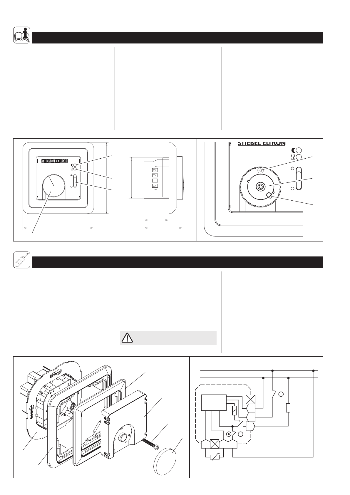
1.1 Bedienung
Nach Einschalten der Fußbodentemperierung
über den Schalter (1) am RTF und dem Erreichen der am Temperaturwählknopf (2) eingestellten Temperatur (zwischen ca. 10 und
45 ºC) wird durch intermittierendes Heizen
der gewünschte Temperaturwert gehalten.
Das Aufheizen ist an der leuchtenden roten
LED-Anzeige (3) zu erkennen.
3
2
1
4
81,5
81,5
Ist eine Zeitschaltuhr an den Regler angeschlossen, senkt dieser zur vorgewählten Zeit
den eingestellten Sollwert um ca. 5K ab. Dieses ist dann an der leuchtenden grünen LEDAnzeige (4) zu erkennen.
1.2 Temperaturbereich-Begrenzung
Der Temperatureinstellbereich kann durch
Einengung des Drehwinkels am Temperaturwählknopf begrenzt werden. Hierfür ist
wie folgt vorzugehen:
4
47
3
1
28,5
44,5
– Temperaturwählknopf (1) mit Hilfe eines
Schraubendrehers vom Gehäuse abhebeln;
– Arretierungsstift (5) mit Spitzzange vor-
sichtig herausziehen;
– Rasterscheiben (6) zur Einstellung der Mi-
nimal- (blau) und/oder Maximaltemperatur
(rot) wie gewünscht verdrehen;
– Arretierungsstift wieder einsetzen;
– Temperaturwählknopf wieder aufsetzen.
7
3
2
1
4
6
5
2
2. Montageanweisung für den Fachmann
Alle elektrischen Anschluss- und Installationsarbeiten sind nach den VDE-Bestimmungen
(DIN VDE 0100 T520 A3), den Vorschriften
des zuständigen EVU’s sowie den entsprechenden nationalen und regionalen Vorschriften auszuführen.
Installation der Schalterdose in Räumen mit
Badewanne und/oder Dusche nur außerhalb
der Schutzbereiche 1 und 2.
Bei Netzausfall bzw. einer Unterbrechung
oder eines Kurzschlusses der Fühlerleitung
wird die Heizung abgeschaltet.
8971.01
2.1 Montage Temperaturfühler
Der Temper aturfühler ist vor dem Aufbringen
des Fußboden-Oberbelages in einem Leerrohr oberflächenbündig im Untergrund (z. B.
Estrich) zu versenken; vgl. Gebrauchs- und
Montageanweisung Temperiermatte.
Die Anschlussleitung des Fühlers kann mit
einen flexiblen Leiter bis 50 m verlängert
werden.
Im Fehlerfall kann Netzspannung an
der Fühlerleitung liegen!
9
L
N
8
Elektronik
7
2
8972.01
2.2 Montage Temperaturregler
Der Temperaturregler ist in eine handelsübliche UP-Schalterdosen für Geräte-Ø 55 mm
einzubauen.
Dabei kann der Regler als separat sitzendes
Gerät oder mittels Zwischenrahmen in verschiedene Flächenschaltersysteme integriertes Gerät installiert werden.
Zum Einsetzen des Temperaturreglers ist wie
folgt vorzugehen:
– Temperaturwählknopf (2) mit Hilfsmittel,
z.B. einem Schraubendreher, vom Gehäuse
abhebeln;
RTF
N
TA
LH
FFL
11
10
2
8973.01
8974.01
Page 3
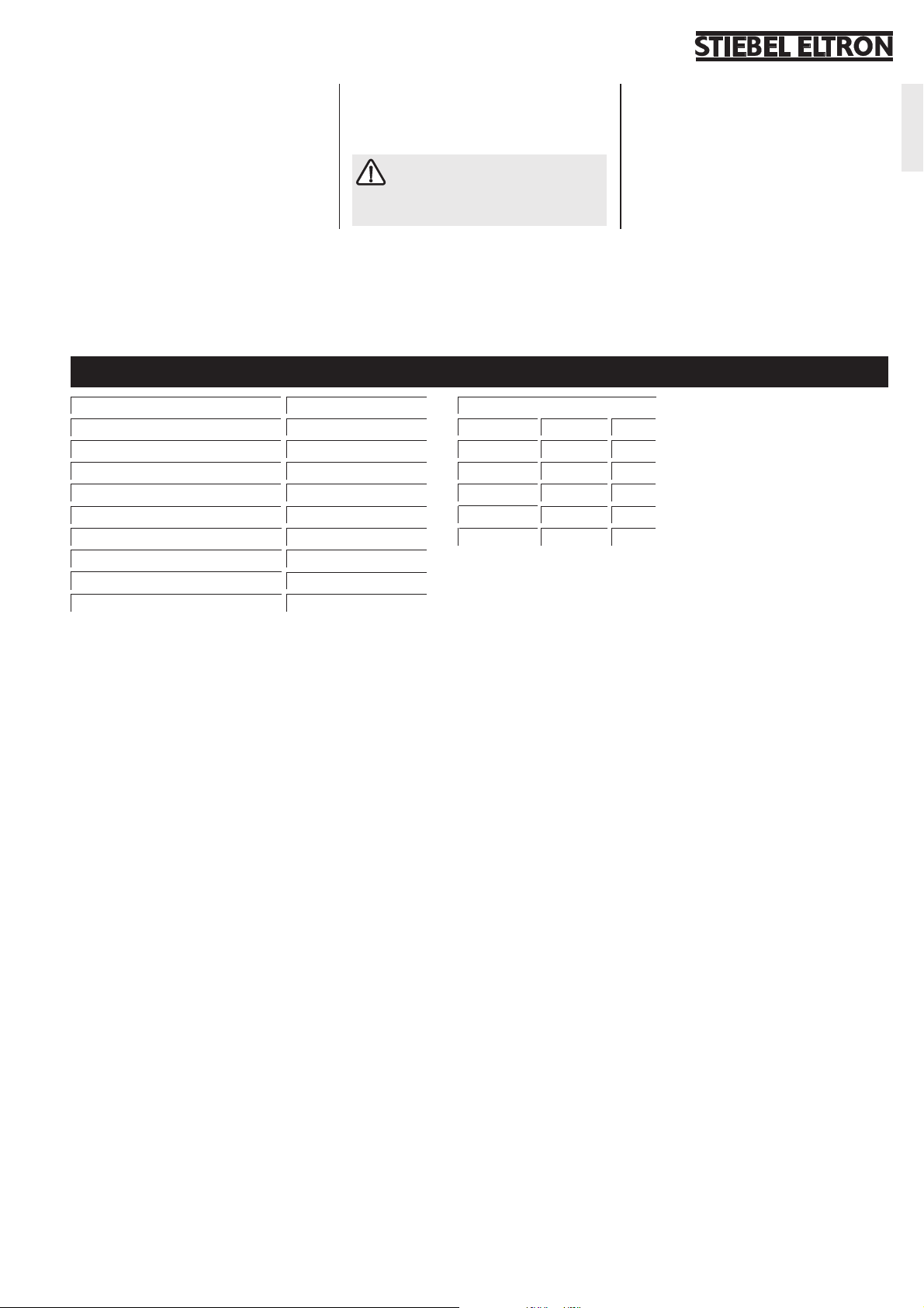
– Befestigungsschraube (7) entfernen und
Gehäusedeckel (8), Zwischenrahmen (9)
und Schalterrahmen (10) abnehmen;
– Elektrischen Anschluss nach dem in dieser
Anweisung abgebildetem Schaltbild vornehmen;
– Temperaturregler in Schalterdose einset-
zen und mit dieser verschrauben;
3. Technische Daten
– Gehäusedeckel, Zwischenrahmen und
Schalterrahmen wieder aufsetzen und festschrauben;
– Temperaturwählknopf wieder aufsetzen.
Montage- und Gebrauchsanweisung
der Fußbodentemperierung, an die
der Temperaturregler angeschlossen werden soll, ist zu beachten.
2.3 Temperaturabsenkung
Mittels einer an die Klemme TA des Temperaturreglers angeschlossen externen Schaltuhr
oder eines Schalters ist eine Temperaturabsenkung um 5 K unterhalb des am Regler eingestellten Wertes möglich.
Deutsch
Ty p R T F
Schaltleistung ~ 12(2) A 230 V
H x B x T 81,5 x 81,5 x 44,5 mm
Einstellbereich ca. 10 ºC . . . 45 ºC
Schaltdifferenz 1 K
Temperaturabsenkung (auf Wunsch) 5 K
Schutzklasse Ι
Schutzart IP 20
Länge Temperaturfühler (DIN 44574) 4 m
Approbationen siehe Geräteaufdruck
Fühlerkennwerte
Temperatur R [kOhm] U [V]
10 °C 3,66 2,49
20 °C 2,43 2,22
30 °C 1,65 1,92
40 °C 1,15 1,63
50 °C 0,82 1,35
3
Page 4

1. Operation instructions for the user and the professional
The RTF controls the heat output of your
under-floor heating system.
1.1 Operation
After switching on the under-floor heating
with the on/off switch (1) on the RTF and
setting the temperature with the temperature
selection knob (2), the floor will heat up and
stay at the set temperature.
During the heating times the red LED light
(3) will illuminate.
3
2
1
4
81,5
If a separate time-switch is installed in
conjunction with the RTF, the green set-back
light (4), will illuminate during the off periods
and set the temperature to approx. 5 K
below the selected temperature.
1.2 Temperature range
limiting
The range of temperatures that can be
chosen can be restricted by using the limiters
located beneath the temperature selection
knob. To do this, take the following actions:
4
81,5
47
3
1
28,5
44,5
– Carefully remove the temperature selection
knob (2) with the help of a screwdriver.
– Remove the locking pin (5) by pulling it out.
– Slide the red (maximum) and / or blue
(minimum) plastic disks (6) to the
appropriate position e.g. Red – 3 and Blue
– 2.
– Replace the locking pin
– Replace the temperature selection knob,
ensuring that the black line is within the
chosen limits before finally pressing into
position.
3
2
1
4
7
6
5
2
2. Installation instructions for the professional
All electrical connections and installation
work must be carried out by a competent
person in accordance with these instructions
and I.E.E. Regulations.
If installed in a bathroom or shower room
the controller must be located outside of
protection zones 1 and 2.
If the sensor probe is damaged, shortcircuited or not connected, the heating
system will be switched off.
8971.01
2.1 Installing the
temperature sensor
The end of the floor temperature sensor
probe must be sited in the floor, within the
area of the heating mat. It is recommended
that the sensor and cable are sited within a
piece of trunking or conduit ( See the Operating and Installation Instructions for the
Heating Mats). The sensor cable can be
extended to up to 50 metres if required.
9
8
7
L
N
Elektronik
2
8972.01
In the case of a fault live electricity
can be present in the controller or
sensor lead.
2.2 Installing the Controller
The controller is designed to be fitted into a
flush back box with an opening of at least
Ø55 mm.
The controller may be installed separately or
in a group of flat-switches by using the
RTF
N
TA
LH
FFL
11
10
4
8973.01
8974.01
Page 5

various frames which belong to the
controller.
To install the controller take the following
steps:
– Carefully remove the temperature
selection knob (2) with the help of a
screwdriver.
– Remove the locating screw (7) and
remove the cover and frames (8,9 and 10).
– Connect the electrical connections in
accordance with the wiring diagram below
and as follows:
! The sensor probes are connected to
the 2 terminals marked ‘F’.
3. Technical data
! The incoming mains electricity
connection should be connected as
follows;
! Live to ‘L’
! Neutral to ‘N’
! Earth to Earth terminal on the back
box.
! The heating mats connections should be
as follows;
! Live to ‘LH’
! Neutral to ‘N’ (common with the
incoming mains supply)
! Earth to Earth terminal on the back
box
– Fit the controller into the back box using
the locating screw holes on the back plate
(11) .
– Refit the frames and cover (8-10).
The Instructions for the controller
and the under-floor heating should
be kept together.
2.3 Set-back Temperature
By using the terminal TA in conjunction with
an external time-switch or a switch, a setback facility, reducing the set temperature by
5K is possible.
English
Type RTF
Switching Capacity ~ 12(2) A 230 V
H x W x D 81,5 x 81,5 x 44,5 mm
Range ca. 10 ºC . . . 45 ºC
Switching Differential 1 K
Set-back (if required) 5 K
Class Ι
Protection rating IP 20
Sensor cable length (DIN 44574) 4 m
Approvals see print on unit
Sensor Values
Temperature R [kOhm] U [V]
10 °C 3,66 2,49
20 °C 2,43 2,22
30 °C 1,65 1,92
40 °C 1,15 1,63
50 °C 0,82 1,35
5
Page 6

1. Инструкция по эксплуатации для специалиста и пользователя
Регулятор температуры RTF служит для
регулировки температуры пола с
устанавливаемым температурным
режимом.
1.1 Обслуживание
После включения подогрева полов с
помощью выключателя (1) на
регйуляторе и достижения температуры,
установленной посредством ручки
выбора температуры (2) (между 10 и
45°С), в ходе периодического
подогрева поддерживается желаемое
значение температуры. Процесс
3
2
1
4
81,5
подогрева можно определить по
светящемуся индикатору (3). Если к
регулятору подключен таймер, то в
заданный интервал времени
установленное значение температуры
понижается примерно на 5К. Это
можно определить по светящемуся
зеленому индикатору (4).
1.2 Ограничение
температурного диапазона
Диапазон установки температуры
можно ограничить путем уменьшения
угла поворота ручки выбора
4
81,5
47
3
1
28,5
44,5
температуры. Для этого необходимо
выполнить следующие шаги:
– снять ручку выбора температуры (1)
при помощи отвертки;
– осторожно извлечь стопорный
фиксатор (5) с помощью инструмента;
– установить шайбы (6) для настройки
минимальной (голубой цвет) и/или
максимальной температуры
(красный цвет);
– установить стопорный фиксатор на
место;
– установить ручку выбора
температуры на место.
7
3
2
1
4
6
5
2
2. Инструкция по монтажу для специалиста
Все работы по электрическому
подключению и установке следует
проводить согласно определениям
Союза немецких электротехников
(DIN VDE 0100 T520 A3), правилам
электроснабжающего предприятия, а
также национальным и региональным
правилам.
Установка коробки для выключателя в
помещениях с ванной и/или душем
запрещена в зонах безопасности 1 и 2!
При разрыве или коротком замыкании
провода температурного датчика
нагрев отключается.
8971.01
2.1 Монтаж
температурного датчика
Перед нанесением верхнего слоя
полового покрытия необходимо
уложить полую трубку для
температурного датчика в основу таким
образом, чтобы поверхность основы
осталась плоской; см. инструкцию по
эксплуатации и монтажу для
нагревательных матов.
С помощью гибкого провода
стандартный провод температурного
датчика можно удлинить до 50 м.
9
8
7
L
N
Elektronik
2
8972.01
При повреждении регулятора
провод температурного датчика
может оказаться под сетевым
напряжением.
2.2 Монтаж регулятора
температуры
Регулятор температуры необходимо
устанавливать в стандартной UP-коробке
для выключателя диаметром 55 мм.
При этом регулятор может быть
установлен как отдельный прибор или с
RTF
N
TA
LH
FFL
11
10
8973.01
6
8974.01
Page 7

помощью промежуточной рамки может
быть интегрирован в различные
системы напольных выключателей.
Для установки регулятора температуры
необходимо выполнить следующие
действия:
– снять ручку выбора температуры (2)
при помощи отвертки;
– выкрутить винт (7) и снять крышку
корпуса (8), промежуточную рамку
(9) и рамку переключателя (10);
– произвести электрическое
подключение согласно схеме,
приведенной в данной инструкции;
– установить регулятор температуры в
коробку для переключателя и
зафиксировать винтовым
соединением;
– установить крышку корпуса,
промежуточную рамку и рамку
переключателя в обратном порядке и
закрепить винтом (7);
– установить ручку выбора
температуры на место.
Необходимо учитывать
требования инструкции по
эксплуатации для нагревательных
матов, к которым должен быть
подключен регулятор температуры.
2.3 Понижение
температуры
С помощью внешнего таймера,
подключенного к клемме ТА регулятора
температуры возможно понижение
температуры на 5К ниже значения,
настроенного на регуляторе.
3. Технические характеристики
Òèï RTF
Коммутационная мощность ~ 12(2) A 230 V
Высота х ширина х глубина 81,5 x 81,5 x 44,5 mm
Диапазон настройки около 10 ºC . . . 45 ºC
Перепад температуры 1 K
Понижение температуры
(внешний таймер)
Класс защиты I
Вид защиты IP 20
Длина провода температурного
датчика (DIN 44574)
Сертификаты см. заводскую табличку с указанием
номинальных данных
OSKO-Service Moskau:
129090 Россия, г. Москва, ул. Троицкая, д.9, к.1
тел.: +7 (095) 933-8774 факс: +7 (095) 933-8775
5 K
4 m
Pyccêèé
Параметры датчика
Температура R [kOhm] U [V]
10 °C 3,66 2,49
20 °C 2,43 2,22
30 °C 1,65 1,92
40 °C 1,15 1,63
50 °C 0,82 1,35
OSKO-Service St.-Petersburg:
197022 Россия, г. С.-Петербург, Каменноостровский пр., д. 50
тел.: +7 (812) 234-9369, 327-5252 факс: +7 (812) 325-1346
7
Page 8

Adressen und Kontakte www.stiebel-eltron.com
Zentrale Holzminden
Stiebel Eltron GmbH & Co. KG
Dr.-Stiebel-Str. 37603 Holzminden
Telefon 0 55 31 / 7 02-0
Fax Zentrale 0 55 31 / 7 02-4 80
E-Mail info@stiebel-eltron.com
Internet www.stiebel-eltron.com
Stiebel Eltron International GmbH
Dr.-Stiebel-Str. 37603 Holzminden
Telefon 0 55 31 / 7 02-0
Fax 05531/702-479
E-Mail info@stiebel-eltron.com
Internet www.stiebel-eltron.com
Unseren zentralen Service
erreichen Sie unter 0 180 3...
... in der Zeit von:
Montag bis Donnerstag 715 bis 1800 Uhr
Freitag 715 bis 1700 Uhr
Info-Center
allgemeine Information
und technische Auskunft
Telefon 0 180 3 - 70 20 10
Telefax 0 180 3 / 70 20 15
E-Mail: info-center@stiebel-eltron.com
0 180 3 -
STI EBEL
7843235
Kundendienst
Telefon 0 180 3 - 70 20 20
Telefax 0 180 3 / 70 20 25
E-Mail: kundendienst@stiebel-eltron.com
Ersatzteil-Verkauf
Telefon 0 180 3 - 70 20 30
Telefax 0 180 3 / 70 20 35
E-Mail: ersatzteile@stiebel-eltron.com
0,09 /min (Stand: 12/02)
Gedruckt auf
100% Recycling-Papier.
Aktiv im Umweltschutz.
7851
Stiebel Eltron Vertriebszentren
Dortmund
Oespel (Indupark)
Brennaborstr. 19 44149 Dortmund
Telefon 02 31 / 96 5022-10
E-Mail: dortmund@stiebel-eltron.com
Frankfurt
Rudolf-Diesel-Str. 18 65760 Eschborn
Telefon 0 61 73 /602-10
E-Mail: frankfurt@stiebel-eltron.com
Hamburg
Georg-Heyken-Straße 4a 21147 Hamburg
Telefon 0 40 / 75 20 18-10
E-Mail: hamburg@stiebel-eltron.com
Holzminden/Info-Center
Berlin/Hannover/Nürnberg
Dr.Stiebel-Straße 37603 Holzminden
Telefon 0 180 3 / 702010
E-Mail: info-center@stiebel-eltron.com
Köln
Ossendorf (Butzweiler Hof)
Mathias-Brüggen-Str. 132 50829 Köln
Telefon 02 21 /597 71-10
E-Mail: koeln@stiebel-eltron.com
Leipzig
Airport Gewerbepark/Glesien
Ikarusstr. 10 04435 Schkeuditz-Glesien
Telefon 03 4207/755-10
E-Mail: leipzig@stiebel-eltron.com
München
Hainbuchenring 4 82061 Neuried
Telefon 0 89/ 89 91 56-10
E-Mail: muenchen@stiebel-eltron.com
Stuttgart
Weilimdorf
Motorstr. 39 70499 Stuttgart
Telefon 07 11/988 67-10
E-Mail: stuttgart@stiebel-eltron.com
Tochtergesellschaften und Vertriebszentren Europa und Übersee
Belgique
Stiebel Eltron Sprl/Pvba
Rue Mitoyenne 897 B-4840 Welkenraedt
087-88 14 65 Fax 087-88 1597
E-Mail stiebel@skynet.be
Internet www.stiebel-eltron.com
∨∨
∨
∨∨
C
eská republika
Stiebel Eltron spol. s r.o.
oo
o
oo
K Háju
m 946 C
∨∨
∨
∨∨
Z-15500 Praha 5-Stodulky
2-511 16111 Fax 2-355 12 122
E-Mail info@stiebel-eltron.cz
Internet www.stiebel-eltron.cz
France
Stiebel Eltron International
Succursale Française à Metz
7-9, rue des Selliers
B.P. 85107 F-57073 Metz-Cédex
03-87-74 38 88 Fax 03-87-74 68 26
E-Mail secretcom@stiebel-eltron.fr
Internet www.stiebel-eltron.fr
Great Britain
Stiebel Eltron Ltd.
Lyveden Road
Brackmills GB-Northampton NN4 7ED
016 04-76 64 21 Fax 016 04-76 52 83
E-Mail info@stiebel-eltron.co.uk
Internet www.stiebel-eltron.co.uk
Magyarország
Stiebel Eltron Kft.
Pacsirtamezo´´ !u.! 41 H-1036 Budapest
012 50-60 55 Fax 013 68-80 97
E-Mail info@stiebel-eltron.hu
Internet www.stiebel-eltron.hu
Nederland
Stiebel Eltron Nederland B.V.
Daviottenweg 36
Postbus 2020 NL-5202 CA 's-Hertogenbosch
073-6 23 00 00 Fax 073-6 23 11 41
E-Mail stiebel@stiebel-eltron.nl
Internet www.stiebel-eltron.nl
Österreich
Stiebel Eltron Ges.m.b.H.
Eferdinger Str. 73 A-4600 Wels
072 42-4 73 67-0 Fax 072 42-4 7367-42
E-Mail info@stiebel-eltron.at
Internet www.stiebel-eltron.at
Polska
Stiebel Eltron sp.z. o.o
ul. Instalatorów 9 PL-02-237 Warszawa
022-8 46 48 20 Fax 022-8 46 67 03
E-Mail stiebel@stiebel-eltron.com.pl
Internet www.stiebel-eltron.com.pl
Sverige
Stiebel Eltron AB
Box 206 SE-641 22 Katrineholm
0150-48 7900 Fax 0150-48 7901
E-Mail info@stiebel-eltron.se
Internet www.stiebel-eltron.se
Schweiz
Stiebel Eltron AG
Netzibodenstr. 23 c CH-4133 Pratteln
061-8 16 93 33 Fax 061-8 16 93 44
E-Mail info@stiebel-eltron.ch
Internet www.stiebel-eltron.com
Thailand
Stiebel Eltron Ltd.
469 Building 77, Bond Street
Tambon Bangpood
Ampur Pakkred Nonthaburi 11120
02-960 1602-4 Fax 02-960 1605
E-Mail stiebel@loxinfo.co.th
Internet www.stiebeleltronasia.com
USA
Stiebel Eltron Inc.
242 Suffolk Street Holyoke MA 01040
04 13-5 38-78 50 Fax 04 13-5 38-85 55
E-Mail info@stiebel-eltron-usa.com
Internet www.stiebel-eltron-usa.com
CAP 185581/33401/2/7860 · ALRE · Änderungen vorbehalten · These instructions are subject to alteration notice! · Возможны ижменения
 Loading...