

Page 1
OPERATION AND INSTALLATION
Central ventilation appliance with heat recovery
» LWZ 170 E plus
» LWZ 370 plus
Page 2

2 | LWZ 170 E PLUS / LWZ 370 PLUS WWW.STIEBEL-ELTRON.COM
CONTENTS | SPECIAL INFORMATION
SPECIAL INFORMATION
OPERATION
1. General information �����������������������������������������3
1.1 Safety instructions ����������������������������������������������� 3
1.2 Other symbols in this documentation ����������������������� 3
1.3 Standardised output data �������������������������������������� 3
1.4 Units of measurement ������������������������������������������ 3
2. Safety ���������������������������������������������������������� 3
2.1 Intended use ������������������������������������������������������ 3
2.2 General safety instructions ������������������������������������ 4
2.3 Test symbols ������������������������������������������������������ 4
3. Appliance description ���������������������������������������4
4. Settings �������������������������������������������������������5
4.1 Remote control ��������������������������������������������������� 5
4.2 User interface on the appliance������������������������������� 5
4.3 Switching the appliance on ������������������������������������ 5
4.4 Switching off the appliance ������������������������������������ 6
4.5 Standard mode ��������������������������������������������������� 6
5. Maintenance, cleaning and care ����������������������������7
5.1 Replacement filter ����������������������������������������������� 7
5.2 Cleaning filters ��������������������������������������������������� 7
6. Troubleshooting ����������������������������������������������9
6.1 Fault analysis ����������������������������������������������������� 9
6.2 Fault codes �������������������������������������������������������� 9
INSTALLATION
7. Safety �������������������������������������������������������� 10
7.1 General safety instructions ����������������������������������� 10
7.2 Instructions, standards and regulations ������������������� 10
7.3 Operation of the appliance in buildings with
combustion equipment ���������������������������������������� 10
8. Appliance description ������������������������������������� 11
8.1 Standard delivery ����������������������������������������������� 11
8.2 Required accessories ������������������������������������������11
8.3 Further accessories��������������������������������������������� 11
9. Preparations ������������������������������������������������ 11
9.1 Installation site �������������������������������������������������� 11
9.2 Transport ��������������������������������������������������������� 11
10. Installation �������������������������������������������������� 11
10.1 Mounting the appliance ���������������������������������������11
10.2 Connecting the condensate drain ��������������������������� 12
10.3 Connecting air ducts ������������������������������������������� 12
10.4 Power supply ���������������������������������������������������� 13
11. Commissioning ��������������������������������������������� 17
11.1 Initial start-up ��������������������������������������������������� 17
11.2 Shutdown �������������������������������������������������������� 17
11.3 Recommissioning ����������������������������������������������� 17
12. Settings ����������������������������������������������������� 17
12.1 Settings menu ��������������������������������������������������� 17
12.2 Read-out menu �������������������������������������������������21
12.3 Service menu ���������������������������������������������������� 21
12.4 Restoring factory settings ������������������������������������� 22
13. Maintenance ������������������������������������������������ 23
14. Troubleshooting �������������������������������������������� 25
15. Specification ������������������������������������������������ 26
15.1 Dimensions and connections ��������������������������������� 26
15.2 Minimum clearances ������������������������������������������� 26
15.3 Data table �������������������������������������������������������� 26
15.4 Wiring diagram ������������������������������������������������� 27
15.5 Sound ������������������������������������������������������������� 27
15.6 Fan diagram �����������������������������������������������������28
GUARANTEE
ENVIRONMENT AND RECYCLING
SPECIAL INFORMATION
- The appliance may be used by children aged8
and up and persons with reduced physical, sensory or mental capabilities or a lack of experience
and know-how, provided that they are supervised
or they have been instructed on how to use the
appliance safely and have understood the resulting risks. Children must never play with the appliance. Children must never clean the appliance
or perform user maintenance unless they are
supervised.
- The power cable must only be replaced (for example if damaged) by qualified contractors authorised by the manufacturer.
- Secure the appliance as described in chapter "Installation/ Installation".
Page 3
OPERATION
General information
ENGLISH
WWW.STIEBEL-ELTRON.COM LWZ 170 E PLUS / LWZ 370 PLUS | 3
OPERATION
1. General information
The chapters "Operation" and “Special Information” are intended
for appliance users and qualified contractors.
The chapter "Installation" is intended for qualified contractors.
Note
Read these instructions carefully before using the appliance and retain them for future reference.
Pass on the instructions to any new user where appropriate.
1.1 Safety instructions
1.1.1 Structure of safety instructions
KEYWORD Type of risk
Here, possible consequences are listed that may result
from failure to observe the safety instructions.
Steps to prevent the risk are listed.
1.1.2 Symbols, type of risk
Symbol Type of risk
Injury
Electrocution
Burns
(burns, scalding)
1.1.3 Keywords
KEYWORD Meaning
DANGER Failure to observe this information will result in serious
injury or death.
WARNING Failure to observe this information may result in serious
injury or death.
CAUTION Failure to observe this information may result in non-seri-
ous or minor injury.
1.2 Other symbols in this documentation
Note
General information is identified by the adjacent symbol.
Read these texts carefully.
Symbol Meaning
Material losses
(appliance damage, consequential losses and environmental pollution)
Appliance disposal
This symbol indicates that you have to do something. The ac-
tion you need to take is described step by step.
1.3 Standardised output data
Explanations to determine and interpret the specified standardised
output data
1.3.1 Standard: EN 13141-7
The output data specifically mentioned in text, diagrams and
technical datasheets has been determined in line with the test
conditions described in the standard shown in the heading of
this chapter.
Generally, these standardised test conditions will not fully meet
the conditions found at the installation site of the system user.
Depending on the chosen test method and the extent to which
the selected method deviates from the conditions described in the
standard shown in the heading of this chapter, any deviations can
have a considerable impact. Further factors that have an influence
on the test values are the measuring equipment, the system configuration, the age of the system and the flow rates.
A confirmation of the specified output data can only be obtained
if the conditions applicable to the relevant test match those of the
standard shown in the heading of this chapter.
1.4 Units of measurement
Note
All measurements are given in mm unless stated otherwise.
2. Safety
2.1 Intended use
The appliance is designed as a mechanical ventilation unit with
centralised supply air and extract air routing.
This appliance is intended for domestic use. It can be used safely
by untrained persons. The appliance can also be used in a non-domestic environment, e.g.in a small business, as long as it is used
in the same way.
Any other use beyond that described shall be deemed inappropriate. Observation of these instructions and of instructions for any
accessories used is also part of the correct use of this appliance.
!
!
Page 4

OPERATION
Appliance description
4 | LWZ 170 E PLUS / LWZ 370 PLUS WWW.STIEBEL-ELTRON.COM
It is deemed inappropriate to:
- Use extract air loaded with grease, explosive gases, dust or
adhesive aerosols
- Install the unit outdoors
- Connect cooker hoods and dryer exhausts to the ventilation
system.
Never adjust the setting of supply and extract air valves inside the
rooms. These have been set up by a qualified contractor during
commissioning.
2.2 General safety instructions
!
WARNING Injury
The appliance may be used by children aged 8 and up and
persons with reduced physical, sensory or mental capabilities or a lack of experience and know-how, provided
that they are supervised or they have been instructed on
how to use the appliance safely and have understood
the resulting risks. Children must never play with the
appliance. Children must never clean the appliance or
perform user maintenance unless they are supervised.
Note
Trouble-free operation of the appliance is only possible
with a closed appliance cover.
2.3 Test symbols
See type plate on the appliance.
3. Appliance description
The appliance draws in outdoor air with a fan. A second fan draws
in extract air from rooms in the home with odour or humidity loads
(kitchen, bathroom and WC). Extract air and outdoor air are routed
through separate ducts. Extract air and outdoor air are filtered
by separate filters.
Both air streams are routed through a cross-countercurrent heat
exchanger. The extract air gives off heat, which is transferred to
the outdoor air. This means that the extracted stale indoor air
heats the fresh clean outdoor air, saving energy and routing fresh
air into the interior.
The appliance has a filter service indicator, as well as an optional
filter service indicator at the stage switch.
The appliance has a frost protection control unit, which ensures
that the appliance works to optimum effect even at low outside
temperatures. If required, the frost protection control unit switches on the integral preheater coil.
The appliance is fully wired when delivered and works fully automatically.
The air flow rate is preset for each fan stage by the qualified
contractor. Constant flow rate control ensures that the air flow
rates of the supply air and extract air are achieved irrespective of
the duct pressure.
Fan stage
Humidity protection ventilation: This fan stage prevents
mould formation using the factory-set air flow rate of
50m³/h. Alternatively, the contractor can set an air flow
rate of 0m³/h when commissioning the appliance. In such
a case, no humidity protection is provided.
Fan stage1 should be seen as background ventilation, to
be selected when going away for example.
Fan stage2 is recommended for standard ventilation.
Fan stage3 is recommended as intensive ventilation, to
temporarily increase the air flow rate for load peaks (e.g.
as a party stage).
Bypass function
An automatic bypass damper is built into the appliance. The bypass damper enables the supply of fresh air, which is not heated by
the heat exchanger. Cool, fresh air is required on summer nights
in particular. In such cases, as much of the warm air in the home
as possible is displaced by cooler fresh air.
The bypass damper opens and closes automatically when the following conditions are met.
Bypass damper
position
Conditions
Open
The outside temperature is higher than 10°C and lower
than the room temperature, and the room temperature is
higher than the bypass temperature set in parameter 05.
Sealed unvented
The outside temperature is lower than 10°C.
The outside temperature is at least 0.5°C higher than the
room temperature.
The room temperature is lower than the bypass tem-
perature reduced by the bypass hysteresis. The bypass
temperature is set in parameter 05. The bypass hysteresis
is set in parameter 06.
When the bypass damper is opened, the extract air does not flow
through the cross-countercurrent heat exchanger, but is instead
routed directly as exhaust air out of the building. This means there
is no transfer of heat to the supply air.
Frost protection
The appliance has a frost protection control unit and an integral
preheater coil to prevent the cross-countercurrent heat exchanger
from freezing up.
Once the frost protection control unit has been enabled (-1.5°C),
the preheater coil is only switched on when the heat exchanger
begins to ice up, at an output that is infinitely variable. The frost
protection control unit detects icing-up of the heat exchanger
when the pressure increases on the extract air side of the appliance. The supply and extract air fans continue to run with the
same air flow rates.
Only when the output of the preheater coil becomes insufficient
for de-icing does the control unit reduce the speed of the supply
air fan variably until it stops.
Page 5
OPERATION
Settings
ENGLISH
WWW.STIEBEL-ELTRON.COM LWZ 170 E PLUS / LWZ 370 PLUS | 5
4. Settings
Note
User operations at the appliance are restricted to switching the appliance ON and OFF.
4.1 Remote control
Observe the operating and installation instructions for the relevant
remote control (see chapter "Appliance description/ Required accessories" or "Appliance description / Other accessories").
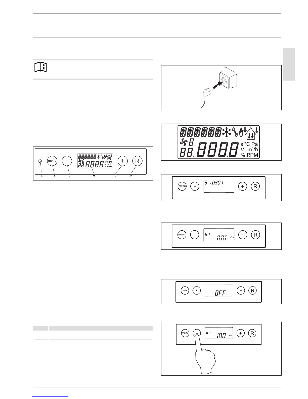
4.2 User interface on the appliance
The appliance has a user interface with display. This enables
air flow rates to be variably adjusted or operating details to be
checked.
.
26�04�15�0008
1 2 3 4 5 6
1 Service plug-in connection
2 Menu key
3 Minus key
4 LCD
5 Plus key
6 R key
With the four control keys (menu, plus, minus, R), you can call up
and change settings.
When the mains power is switched on, all available symbols are
displayed for two seconds. In addition, the backlighting is activated for 60seconds. If one of the control keys is pressed, the display
is illuminated for 30 seconds.
If no keys are pressed and/or if no blocking fault occurs, standard
mode is displayed.
When the menu key is pressed, you can use the plus or minus key
to choose between three different sub-menus:
- Settings menu (SET)
- Read-out menu (READ)
- Service menu (SERV)
With the R key, you can exit any selected menu and return to
standard mode.
To switch on the display backlight without changing anything in
the menu, press the R key briefly (less than 5 seconds).
Button Key function
Menu Open menu; open sub-menu; enable parameter for value change;
confirm value change
- Scroll; adjust value; switch appliance on or off from standard mode
(press and hold down for 5 seconds)
+ Scroll; adjust value
R One step back in the menu; reset adjusted value; filter reset (press
and hold down for 5 seconds); delete fault history
4.3 Switching the appliance on
Plug the appliance into a standard socket.
26�04�15�0009
All display symbols are shown for two seconds.
26�04�15�0011
The software version is displayed for two seconds.
26�04�15�0029
The appliance then runs according to the stage switch setting. If
no stage switch is connected, the appliance always runs in fan
stage1.
26�04�15�0030
Switching on via software
If the appliance has been switched off via software, "OFF" is displayed.
26�04�15�0032
Switch on the appliance by pressing the minusbutton for 5
seconds.
5 s
26�04�15�0031
Page 6
OPERATION
Settings
6 | LWZ 170 E PLUS / LWZ 370 PLUS WWW.STIEBEL-ELTRON.COM
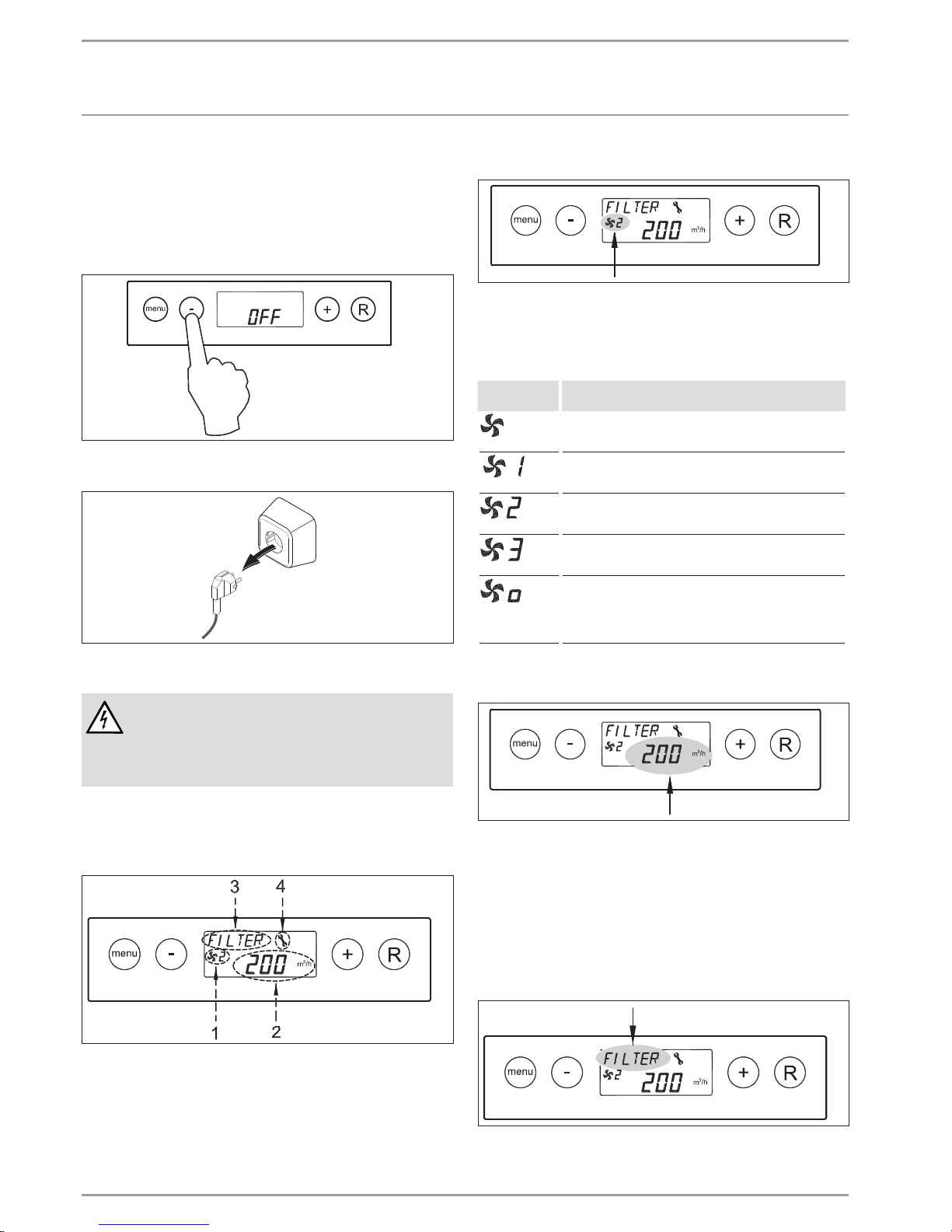
4.4 Switching off the appliance
Switching off via software
Press and hold down the minus button for 5 seconds to
switch off the appliance.
The display shows "OFF".
5s
26�04�15�0048
Interrupting the power supply
26�04�15�0010
The display is now blank.
WARNING Electrocution
Before working on the appliance, always isolate the
appliance from the power supply by first switching the
appliance off via the software and then unplugging it
from the mains.
4.5 Standard mode
In standard mode, the display shows up to four different pieces of
information (operating modes and values) simultaneously.
26�04�15�0012
1 Indication of the fan stage, indication of connected
appliances
2 Indication of the air flow rate
3 Message text, e.g. filter status text, triggering of external
switching contact, etc.
4 Fault symbol
4.5.1 Fan stage
26�04�15�0013
A fan symbol is displayed when the supply air fan and the extract
air fan rotate. The fan symbol is not visible when the fans are at
a standstill.
The number after the fan symbol indicates the fan stage.
Fan stage indicator
Description
The supply air and extract air fans generate an air flow rate
of 50m³/h or stop. This depends on the setting of parameter
01. This fan stage cannot be enabled with a 3-stage switch.
The supply air and extract air fans rotate according to
stage1 of the stage switch. The air flow rate depends on the
parameter 02 setting.
The supply air and extract air fans rotate according to
stage2 of the stage switch. The air flow rate depends on the
parameter 03 setting.
The supply air and extract air fans rotate according to
stage3 of the stage switch. The air flow rate depends on the
parameter 04 setting.
This appliance has been connected using an eBUS or OpenTherm coupling. The supply air and extract air fans rotate
according to the fan stage selected at the master appliance.
If the appliance is connected in a cascade, the slave number
of the appliance is displayed.
4.5.2 Indication of the air flow rate
26�04�15�0014
The selected air flow rate of the supply air and extract air fans is
displayed.
If the air flow rates of the supply air and extract air fans differ,
e.g. when an external switching contact is used, the highest air
flow rate is always displayed.
When the appliance is switched off via software, the text "OFF"
appears.
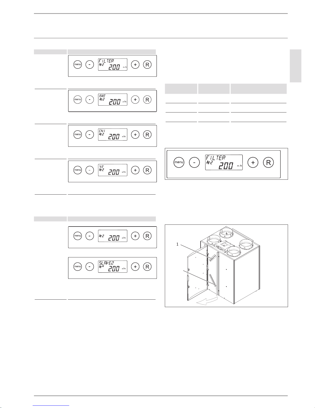
4.5.3 Message texts in standard mode
26�04�15�0049
At this point on the display, a message text may appear. The message text "FILTER" always takes priority over other message texts.
Page 7
OPERATION
Maintenance, cleaning and care
ENGLISH
WWW.STIEBEL-ELTRON.COM LWZ 170 E PLUS / LWZ 370 PLUS | 7
Message text Description
FILTER
If FILTER is displayed, the filter must be cleaned or replaced.
EWT
If EWT is displayed, the geothermal heat exchanger is
enabled.
CN1 or CN2
If CN1 or CN2 is displayed, one of the external switching
inputs is enabled.
V1 or V2
If V1 or V2 is displayed, one of the 0-10V inputs is enabled.
Only when connection X1 is used (eBUS or OpenTherm connection):
Message text Description
Slave 1, Slave 2, etc.
Master appliance:
Slave appliance:
With connected appliances, the message tex t indicates
which appliance is the "Slave 1" to "Slave 9". The default
display for fan operation is indicated on the master
appliance.
5. Maintenance, cleaning and care
Maintenance by the user is limited to filter cleaning or replacement
required at certain intervals.
5.1 Replacement filter
Product designation
Part number Description
FMSG4-10 232475 Coarse particle filter mat G4;
10 pce per packing unit
FMSF5-2 232476 Fine filter F5;
2pce per packing unit
FMSF7-2 23247 7 Fine filter F7;
2pce per packing unit
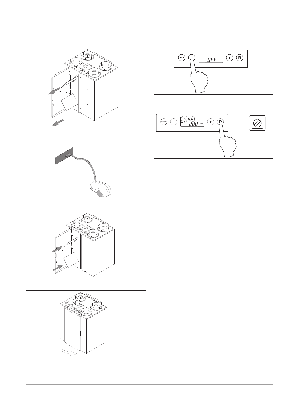
5.2 Cleaning filters
Filters must be cleaned when "FILTER" is displayed.
26�04�15�0050
Replace filters annually.
Never operate the appliance without filters.
Cleaning or replacing filters
Press and hold down the minus button for 5 seconds to
switch off the appliance.
26�04�15�0037
1
2
1 Extract air filter
2 Supply air filter
Open the filter door.
Page 8
OPERATION
Maintenance, cleaning and care
8 | LWZ 170 E PLUS / LWZ 370 PLUS WWW.STIEBEL-ELTRON.COM
26�04�15�0039
Extract the supply air and extract air filters. Make a note of
how the filters were fitted.
26�04� 15�0015
Clean the filters, e.g. with a vacuum cleaner.
26�04�15�0040
Push the cleaned or new filter into the appliance.
26�04�15�0041
Close the filter door.
> 5 s
26�04�15�0016
Switch on the appliance by pressing the minusbutton for 5
seconds.
5s
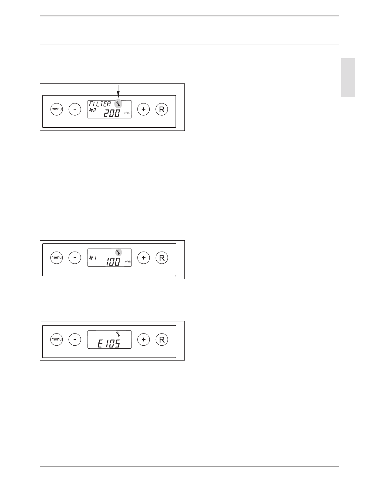
1
2 3
26�04�15�0059
After cleaning or replacing the filters, hold down the R key
for 5 seconds to reset the filter display.
To confirm that the filters have been reset, the text "FILTER" will
flash briefly. Even if the message "FILTER" has not yet been displayed, it is possible to reset the filter. The counter is then reset
to zero.
Once the filter has been reset, the text "FILTER" disappears and
standard mode is displayed again.
Page 9
OPERATION
Troubleshooting
ENGLISH
WWW.STIEBEL-ELTRON.COM LWZ 170 E PLUS / LWZ 370 PLUS | 9
6. Troubleshooting
6.1 Fault analysis
26�04�15�0060
If the appliance detects a fault, a flashing fault symbol (spanner)
is displayed, possibly together with a fault number.
The appliance differentiates between a fault, where the appliance
continues to operate with limited functionality, and a blocking
fault, where both fans are stopped.
In the event of a blocking fault, the settings and read-out menus
are also switched off and access is restricted to the service menu.
The appliance remains in this fault condition until the problem has
been resolved. The appliance then resets itself (auto reset) and
standard mode is displayed again.
6.2 Fault codes
Non-blocking fault
26�04�15�0061
If the appliance detects a non-blocking fault code, it continues to
operate with limited functionality. Non-blocking faults are displayed with the fault symbol (spanner).
Blocking fault
D0000036353
If the appliance detects a blocking fault code, it stops. The permanently illuminated display shows the fault symbol (spanner)
together with a fault code.
Notify a qualified contractor, who can correct the fault.
A blocking fault cannot be resolved by briefly disconnecting the
appliance from the power supply. The fault itself must first be
rectified.
If you cannot remedy the fault, notify your qualified contractor.
To facilitate and speed up your request, provide the number from
the type plate (000000-0000-000000).
Page 10

10 | LWZ 170 E PLUS / LWZ 370 PLUS WWW.STIEBEL-ELTRON.COM
INSTALLATION
Safety
INSTALLATION
7. Safety
Only a qualified contractor should carry out installation, commissioning, maintenance and repair of the appliance.
7.1 General safety instructions
We guarantee trouble-free function and operational reliability only
if original accessories and spare parts intended for the appliance
are used.
7.2 Instructions, standards and regulations
Note
Observe all applicable national and regional regulations
and instructions.
7.3 Operation of the appliance in buildings with
combustion equipment
If the building contains combustion equipment (tiled stoves, fireplaces, etc.), the responsible flue gas inspector must be consulted
in the planning phase. The flue gas inspector assesses whether all
statutory regulations are being observed. Here, a differentiation
is made between balanced and open flue combustion equipment.
For simultaneous operation of combustion equipment and a mechanical ventilation system, we recommend choosing approved
room sealed combustion equipment (in Germany, DIBt approval).
7.3.1 Room sealed combustion equipment
In conjunction with room sealed combustion equipment, no additional precautions are generally required. Assessment is carried
out by the flue gas inspector.
7.3.2 Open flue combustion equipment
!
WARNING INJURY
If open flue combustion equipment is operated with the
mechanical ventilation system, tested safety equipment
must be installed. The combustion equipment must also
have a separate combustion air supply.
With open flue combustion equipment, a differentiation must be
made between alternate and simultaneous operation of the ventilation system and combustion equipment.
Alternate operation
Operation on alternate sides means that, when the combustion
equipment is commissioned, the mechanical ventilation system is
switched off and/or cannot be started.
Simultaneous operation
!
WARNING INJURY
To prevent any flue gas escaping into the installation
room, it is necessary to ensure that sufficient combustion
air is supplied or that the negative pressure in room
where the stove is installed is not greater than 4 Pa.
Tested safety equipment must be installed to monitor the
chimney draught (differential pressure monitoring) and
to switch off the ventilation unit in the event of a fault.
Connect the safety equipment according to the chapter "Installation / Electrical connection/ ConnectionX15/ Connecting safety
equipment for stove/fireplace operation".
The equipment for differential pressure monitoring should fulfil
the following requirements:
- Monitoring of the differential pressure between the connection piece to the chimney and the room where the combustion equipment is installed.
- Possibility of matching the shutdown value for the differential
pressure to the minimum draught requirement for the combustion equipment.
- Floating contact to switch off ventilation.
- Optional connection of a temperature capturing device so
that differential pressure monitoring is only enabled when
the combustion equipment is in operation and so that unwanted shutdowns due to environmental influences can be
avoided.
Note
Differential pressure switches that use the pressure
differential between the outdoor air pressure and the
pressure in the room where the combustion equipment
is sited as a response criterion are not suitable.
Connect the safety equipment with a floating contact (see
chapter "Electrical connection / Connection X15").
The mechanical ventilation system is switched off when the safety
equipment responds.
Note
The maximum available external pressure (see chapter
"Specification/ Data table") must not be exceeded.
Page 11

ENGLISH
WWW.STIEBEL-ELTRON.COM LWZ 170 E PLUS / LWZ 370 PLUS | 11
INSTALLATION
Appliance description
8. Appliance description
8.1 Standard delivery
The following are delivered with the appliance:
- Wall mounting bracket set (2mounting brackets, 3protective caps, 1rubber strip, 2rubber rings, 1 set of installation
instructions)
- PVC condensate drain connection (1plastic nut1.5”, 1sealing
ring, 1glued joint PVC fitting32 mm)
- Approx. 90 cm long cable for connecting a remote control
8.2 Required accessories
- Hardwired remote control used to control the air flow rates
preset in three stages. Our range of accessories includes remote control units with additional functions.
8.3 Further accessories
You can also obtain ventilation pipes, extract air and supply air
valves and similar accessories from us.
9. Preparations
9.1 Installation site
The appliance can be mounted on the wall with the wall mounting
bracket set supplied.
!
Material losses
For vibration-free mounting, a solid wall with a minimum
mass of 200kg/m2 is required. A plaster board or metal
framed wall is inadequate. Additional measures such as
a double skin or additional supports would be needed
in such cases.
Ensure the equipment is level after installation.
The installation site must have an adequate condensate drain with
stench trap and a fall for the condensate.
The installation site must be free from the risk of frost.
9.2 Transport
To protect the appliance against damage, you should transport it
to the installation room inside its original packaging.
10. Installation
10.1 Mounting the appliance
10 mm
26�04� 15�0078
Undo the two top crosshead screws on the back of the
appliance.
Secure one of the two rails to the appliance with screws.
!
Material losses
Check whether the wall can bear the weight of the
appliance.
Use appropriate rawl plugs and screws suitable for
the wall structure to attach the rail.
Mount the second rail on the wall as a retainer. To avoid
sound transmission, place the washers supplied between the
wall and the rail.
Affix the spacers supplied to the back of the appliance.
26�04� 15�0079
Place the rubber strips supplied on the rail mounted on the
wall. The rubber strips are also meant to provide additional
anti-vibration separation.
Fit the appliance so that the two rails interlock.
Page 12

12 | LWZ 170 E PLUS / LWZ 370 PLUS WWW.STIEBEL-ELTRON.COM
INSTALLATION
Installation
10.2 Connecting the condensate drain
!
Material losses
Never kink the hose, to ensure the condensate drains perfectly. The fall must be at least 10%, and the appliance
must be horizontal.
> 60
D0000046572
2
1
1 Condensate drain
2 Condensate drain connector (Ø32mm) with union nut
The condensate drain is routed through the floor plate. The condensate must drain away via the domestic sewer system.
Secure the condensate drain connector supplied along with
the gasket and union nut to the condensate drain located underneath the appliance.
You can fit the condensate drain pipe (bent if required) to this
condensate drain connector with a glued joint.
Before connecting the condensate drain to the appliance,
pour water into the siphon to create a stench trap.
The condensate drain pipe must terminate below the water level
in the siphon. The condensate drain pipe must be immersed in
the water in the siphon by at least 60 mm.
10.3 Connecting air ducts
During installation, ensure that no metal swarf enters the
ductwork. However, should this occur, remove this debris, otherwise the fans may be damaged.
External wall ducts
Supply outdoor air from a location where contamination (dust,
soot, odours, flue gas, exhaust air) is as low as possible.
When installing external wall ducts, prevent any short circuit between the air intake and the air discharge.
Silencers
Always install a silencer in both the supply air duct and the extract
air duct. We recommend installing additional silencers if required
to avoid sound transmission.
If a room with a high noise level must be ventilated, install additional silencers upstream of this room to reduce sound transmission to adjacent rooms.
Aspects such as carried voices and impact sound must also be
taken into consideration in the case of ducts embedded in concrete. Carried voices should be avoided by designing the duct with
separate branches to the valves. If required, insulate the supply air
ducts, e.g. if they are outside the insulated wall panel.
Overflow apertures
In living rooms and bedrooms, air is only blown in. Air is only
extracted from rooms where odours and moisture are generated.
Ventilation grilles must be installed in internal doors or walls,
or the air gap beneath the door must be increased to ≥ 8 mm to
ensure an unobstructed air flow.
Insulation against condensation
!
Material losses
When warm air meets cold surfaces, condensation can
result.
For outdoor air and exhaust air ducts, use va-
pour-proof thermally insulated pipes.
If you use uninsulated pipes and moulded parts for
this pipework, ensure that they are adequately insulated.
Insulate the supply air and extract air ducts if they
are routed through unheated rooms.
The extract air duct does not require a control valve, because the
necessary air flow rates are controlled by the appliance itself.
Page 13

ENGLISH
WWW.STIEBEL-ELTRON.COM LWZ 170 E PLUS / LWZ 370 PLUS | 13
INSTALLATION
Installation
10.4 Power supply
WARNING Electrocution
Carry out all electrical connection and installation work
in accordance with national and regional regulations.
WARNING Electrocution
Before connecting the appliance to the mains power supply, isolate all power cables. Isolation from the mains
power supply must be carried out with a contact separation of at least 3 mm, e.g. by means of omnipolar
isolators.
The appliance can be connected at a socket using the plug fitted
to the appliance.
Take the power consumption of the preheater coil into consideration.
10.4.1 Terminal X1
Connection for eBUS or OpenTherm plug-in connection
The appliance can operate with both an OpenTherm and an eBUS
protocol. Provide the accessories required for this on site.
Subject to the setting of parameter 08 in the settings menu, you
can choose between eBUS and OpenTherm.
X1
26�04�15�0019
To connect an eBUS or OpenTherm connection, there is a 2-pole
X1 connection on the back of the display cover.
The eBUS protocol can, for example, be used to link appliances
(cascade control). In the context of sensitivity to polarity, always
connect contacts X1-1 and X1-1, and contacts X1-2 and X1-2. If the
contacts are interchanged, the appliance will not work.
With the OpenTherm protocol, swapping over the cable connection
at the 2-pole screw connection X1 does not affect the functioning
of the appliance.
The eBUS connection is set as default in parameter08.
The X1 connection is only suitable for low voltage.
10.4.2 X2 connection
Connecting a stage switch
Note
Route the stage switch cable and power cable for the
ventilation unit separately.
X2
26�04�15�0019
Connect the stage switch (not part of standard delivery) to the
modular plug-in connection, type RJ12 (X2 connection). The X2
connection is on the back of the appliance's display cover.
Depending on which stage switch is connected, connect a type
RJ11 or RJ12 plug.
- When using a 4-stage switch with filter status indicator,
connect an RJ12 plug in conjunction with a 6-wire modular
cable.
- When using a 3-stage switch without filter status indicator,
connect an RJ11 plug in conjunction with a 4-wire modular
cable.
A combination of stage switches is also possible. The X2 connection is only suitable for low voltage.
10.4.3 Connection X14
X14
26�04�15�0003
The X14 connection is used to connect an external reheater coil.
The 2-pole X14 connection can be accessed once you have removed the display cover. The display cover has a second union nut.
This union nut enables any connected 230V cable, which can be
connected at X14, to be routed out of the appliance.
The X14 connection is disabled as default.
If you connect a reheater coil, adjust parameter13 in the set-
tings menu.
The max. permissible connected load is 1000W.
If you connect a reheater coil, also connect the temperature
sensor for the reheater coil across X15-7 and X15-8.
Secure the power cable that is routed to the reheater coil
using the strain relief below the display cover.
Page 14

14 | LWZ 170 E PLUS / LWZ 370 PLUS WWW.STIEBEL-ELTRON.COM
INSTALLATION
Installation
10.4.4 Connection X14
1 2 3 4 5 6 7 8 9
26�04�15�0002
The 9-pole X15 terminal strip can be accessed on the back of the
display cover without having to open the appliance.
Connection X14 Purpose Parameter 15 Parameter 21
1 & 2 External switching contact 0 N/O contact (factory set ting)
1 0 - 10V input; X15-1 = GND & X15-2 = 0 - 10V
2 N/C contact
3 Switching input 1: Bypass open = 12V; bypass closed = 0V
4 Switching input 1: Bypass open = 0V; bypass closed = 12V
3 & 4 Input 0 - 10V 0 N/O contact
1 0 - 10Vinput (= factory setting)
2 N/C contact
3 Switching input 2: Bypass open = 12V; bypass closed = 0V
4 Switching input 2: Bypass open = 0V; bypass closed = 12V
5 & 6 24V connection max. 4.5V A; 5 = earth; 6 = +
7 & 8
Connection of sensor for reheater coil or outside temperature
for geothermal heat exchanger
9 Valve control signal (0 or 10V) 9 = + ; 5 = ear th
Page 15

ENGLISH
WWW.STIEBEL-ELTRON.COM LWZ 170 E PLUS / LWZ 370 PLUS | 15
INSTALLATION
Installation
Connection of an external switching contact across X15-1 and
X15-2
By adjusting parameter 18, when the input of "external switching
contact 1 (X15-1 and X15-2)" is closed, you can set five different
operating modes for the supply air and extract air fans. Subject
to the setting for parameters 19 and 20, the supply air and extract
air fans can deliver different air flow rates (maximum air flow rate
is displayed).
Parameter 18
Function conditions
Supply air fan and extract air fan operating
mode
Parameter 19
Parameter 20
Action, supply air or extract
air fan when closing contact
input X15-1& X15-2
0 Contact input1 (X15-1 & X15-2)
closed
No action possible, because contact input 1 has not been enabled (parameter 18 is still on 0)
1 Contact input1 (X15-1 & X15-2)
closed
Action dependent on the setting for the supply air fan
(parameter 19) and the extract air fan (parameter 20)
0 0 Fan switches of f
1 1 Fan on minimum air flow rate
(50m3/h)
2
Contact input1 (X15-1 & X15-2)
closed; bypass conditions for
"Damper open" are met
2
2
Fan on air flow rate stage 1
3 3 Fan on air flow rate stage 2
4 4 Fan on air flow rate stage 3
3
Contact input1 (X15-1 & X15-2)
closed
The bypass damper opens; automatic bypass control unit
in the appliance is 'overridden'; action of the fans subject
to parameters 19 and 20.
5
5
Fan on air flow rate step switch
6 6 Fan on max. air flow rate
4
Contact input
X15-1 & X15-2 closed
The supply air diverter valve opens. The supply air diverter valve (24V) is connected to X15-5 (24V GND), X15-6
(24V +) and X15-9 (0-10V control unit); the action of the
fans is subject to parameters 19 and 20.
7
7
No fan control
If connections X15-3 and X15-4 are programmed as switching
input2, you can use parameters 24, 25 and 26 to set the individual
operating modes similarly to contact input 1. When contact input2
is closed, "CN2" is displayed.
10.4.5 Connection of safety equipment for operation of a stove/
fireplace
Version 1: Connection of safety equipment at X15
Close the safety equipment floating contact for stove/fireplace
operation at X15-1 and X15-2.
Set parameter 18 to 1, and parameters 19 and 20 to 0. If the
safety equipment closes the power circuit across X15-1 and
X15-2, the extract air fan and the supply air fan are switched
off.
Version 2: Power supply interruption through safety equipment
Connect the safety equipment in accordance with the diagram
in chapter "Electrical connection/ Standard circuit".
Page 16

16 | LWZ 170 E PLUS / LWZ 370 PLUS WWW.STIEBEL-ELTRON.COM
INSTALLATION
Installation
10.4.6 Standard circuit
L
N
PE
1/N/PE
230V ~50Hz
Lüftungsgerät
6 x 0,5 mm² max. 30 m
Schalter
Kaminbetrieb
Ofen
Raum
Druckanschluss
Differenzdruckcontroller für Feuerstätten
X2
ZLWZ 4S
24 V
P (0V)0 2 3LED
24 V
P (0V)0 2 3LED
FEZ
24 V
P (0V)0 23 LED
12104 115
FEQ
24 V
P (0V)02 3LED
64
251
3-Stufen-Schalter
24 V
P (0V)0 23 LED
3
2
1
D0000055737
3-Stufen-Schalter 3-stage switch
ZLWZ 4S 4-stage switch
FEQ Air quality sensor
FEZ Remote control
Lüftungsgerät Ventilation unit
Ofen Stove
Raum Room
Druckanschluss Pressure connection
Schalter Kaminbetrieb Switch, fireplace operation
Differenzdruckcontroller
für Feuerstätten
Differential pressure controller for combustion equipment
Page 17

ENGLISH
WWW.STIEBEL-ELTRON.COM LWZ 170 E PLUS / LWZ 370 PLUS | 17
INSTALLATION
Commissioning
11. Commissioning
11.1 Initial start-up
11.1.1 Setting the air flow rate
Output and energy consumption of the appliance depend on the
pressure drop in the duct system and the resistance of the filters.
Fan stage Air flow rate
m³/h
0
50: Moisture protection ventilation
This fan stage prevents mould formation using the
factory-set air flow rate of 50m³/h.
m³/h must be lower than for stage 2
m³/h must be lower than for stage 3
m³/h LWZ 370 plus: 50 - 400
m³/h LWZ 170 E plus: 50 - 300
The air flow rate of the higher fan stage is automatically selected
if one of the above conditions is not met.
11.2 Shutdown
Even during longer periods away from home, we recommended
that the equipment should be allowed, via the remote control,
to run at switch position1. If you nevertheless need to take the
appliance out of use for an extended period, switch it off via the
user interface and unplug it from the mains to isolate it from the
power supply.
Clean or replace filters.
11.3 Recommissioning
Check whether filters are fitted in the appliance. Never start
the appliance without filters.
Check whether the condensate drain is damaged or kinked.
12. Settings
12.1 Settings menu
For optimum appliance function, you can change parameters used
to adapt the appliance to the actual installation. Some parameter
settings such as the air flow rates have been set out in the technical
details appertaining your individual building.
Note
Changes to settings not described may only be made by
agreement with the manufacturer. Incorrect settings may
impair the correct appliance function.
12.1.1 How to set parameters
Selecting the settings menu
Press menu in standard mode.
The settings menu is displayed ("SET").
26�04�15�0064
Enabling the settings menu
Press menu again to enable the settings menu.
26�04�15�0065
Selecting parameters
Use the plus or minus key to select the parameter you want
to set.
26�04�15�0066
1 2
1 Parameter number
2 Parameter value
Page 18

18 | LWZ 170 E PLUS / LWZ 370 PLUS WWW.STIEBEL-ELTRON.COM
INSTALLATION
Settings
Parameter change
Press menu.
26�04�15�0067
The parameter value starts to flash.
Use plus or minus to change the parameter value.
26�04�15�0068
Discarding a parameter change
If you do not want to save the changed parameter value,
press R.
26�04�15�0069
Confirm parameter value
26�04� 15�0070
If you want to save the changed parameter value, press
menu.
Note
To change other parameters, repeat the steps described
from "Selecting parameters". If you do not want to change
any more parameters, press R to return to standard mode.
Page 19

ENGLISH
WWW.STIEBEL-ELTRON.COM LWZ 170 E PLUS / LWZ 370 PLUS | 19
INSTALLATION
Settings
12.1.2 List of parameters in the settings menu
Parameter
Description
Unit Factory setting
Setting range Step
size
Display text
and symbols
01
Air flow rate of stage
m3/h 50 0
50: Moisture protection ventilation
02 Air flow rate of stage 1 m
3
/h 100 LWZ 370 plus: 50 - 400 5
LWZ 170 E plus: 50 - 300
03 Air flow rate of stage 2 m
3
/h LWZ 370 plus: 200 LWZ 370 plus: 50 - 400 5
LWZ170Eplus: 150 LWZ 170 E plus: 50 - 300
04 Air flow rate of stage 3 m
3
/h LWZ 370 plus: 300 LWZ 370 plus: 50 - 400 5
LWZ170Eplus: 225 LWZ 170 E plus: 50 - 300
05 Bypass temperature °C 22 15 - 35 0.5
BYPA SS
06 Bypass hysteresis °C 2 0 - 5 0.5
BY HYS
07 Bypass damper function 0 0 (Automatic function)
BYPA SS
1 (Bypass damper closed)
2 (Bypass damper open)
08 Communication eBUS
OT (OpenTherm)
eBUS OT/BUS
09 BUS address 0 0 - 9 (0 = master) BUSADR
10 Introduction of an additional extract
air flow.
OFF As default, this parameter must remain OFF for this
appliance.
CV+WTW
11 Pressure imbalance permissible ON
OFF (Air flow rate for supply/extract air the same)
ON (Pressure imbalance permissible)
12 Fixed pressure imbalance m3/h 0 -100 - 100 1
13 Heating coils 0 0 (Aus)
HEATER
1 (Preheater coil)
2 (Reheater coil)
14 Reheater coil temperature °C 21 15 - 30 0.5
HEATER
15 Selection, switching input1 0 0 (N/O contact) V1
1 (0 - 10V input)
2 (N/C contact)
3 (Bypass open = 12V; bypass closed = 0V)
4 (Bypass open = 0V; bypass closed = 12V)
16 Minimum voltage, switching input1 V 0 0 - 10 0.5 V1 MIN
17 Maximum voltage, switching input1 V 10 0 - 10 0.5 V1 MAX
18 Conditions, switching input1 0
0 (Aus) CN1
1 (Ein)
2 (On, if conditions for open bypass are met)
3 (Bypass control)
4 (Supply air diverter valve)
19 Supply air fan mode, switching
input 1
5
0 (Supply air fan off)
CN1
1 (Absolute minimum air flow rate 50 m3/h)
2 (Air flow rate stage 1)
3 (Air flow rate stage 2)
4 (Air flow rate stage 3)
5 (Step switch)
6 (Max. air flow rate)
7 (No supply air fan control)
Page 20

20 | LWZ 170 E PLUS / LWZ 370 PLUS WWW.STIEBEL-ELTRON.COM
INSTALLATION
Settings
Parameter
Description
Unit Factory setting
Setting range Step
size
Display text
and symbols
20 Extract air fan mode,
switching input 1
5
0 (Extract air fan off)
CN1
1 (Absolute minimum air flow rate 50 m3/h)
2 (Air flow rate stage 1)
3 (Air flow rate stage 2)
4 (Air flow rate stage 3)
5 (Step switch)
6 (Max. air flow rate)
7 (No extract air fan control)
21 Selection, switching input2 1 0 (N/O contact) V2
1 (0 - 10V input)
2 (N/C contact)
3 (Bypass open = 12V; bypass closed = 0V)
4 (Bypass open = 0V; bypass closed = 12V)
22 Minimum voltage, switching input2 V 0 0 - 10 0.5 V2 MIN
23 Maximum voltage, switching input2 V 10 0 - 10 0.5 V2 MAX
24 Conditions, switching input 2 0
0 (Aus) CN2
1 (Ein)
2 (On, if conditions for open bypass are met)
3 (Bypass control)
4 (Supply air diverter valve)
25 Supply air fan mode, switching
input2
5
0 (Supply air fan off)
CN2
1 (Absolute minimum air flow rate 50 m3/h)
2 (Air flow rate stage 1)
3 (Air flow rate stage 2)
4 (Air flow rate stage 3)
5 (Step switch)
6 (Max. air flow rate)
7 (No supply air fan control)
26
Extract air fan mode, switching
input 2
5
0 (Extract air fan off)
CN2
1 (Absolute minimum air flow rate 50 m3/h)
2 (Air flow rate stage 1)
3 (Air flow rate stage 2)
4 (Air flow rate stage 3)
5 (Step switch)
6 (Max. air flow rate)
7 (No extract air fan control)
27 Geothermal heat exchanger OFF
OFF (Valve control for geothermal heat exchanger of f) EWT
ON (= Valve control for geothermal heat exchanger on)
28
Minimum temperature for geothermal heat exchanger (below this temperature, the valve opens)
°C 5
0 - 10
0.5
EW T T-
29
Maximum temperature for geothermal heat exchanger (above this temperature, the valve opens)
°C 25
15 - 40
0.5
EW T T+
Page 21

ENGLISH
WWW.STIEBEL-ELTRON.COM LWZ 170 E PLUS / LWZ 370 PLUS | 21
INSTALLATION
Settings
12.2 Read-out menu
With the read-out menu, you can call up some values for more
detailed information on the function of the appliance. Values and
settings cannot be changed in the read-out menu.
Press menu in standard mode.
The settings menu is displayed ("SET").
26�04�15�0064
Press plus or minus to switch to the read-out menu.
26�04� 15�0071
Press menu to enable the read-out menu.
26�04� 15�0072
Use plus or minus in the read-out menu to move to the required
parameter.
26�04� 15�0073
1 2
Parameter Description of the actual value Unit
01 Room temperature °C
02 Outside temperature (captured by the outside temper-
ature sensor)
o
C
03 Bypass status (ON = Bypass damper open,
OFF = Bypass damper closed)
04 Frost protection status (ON = Frost protection enabled,
OFF = Frost protection disabled)
05 Supply air duct pressure Pa
06 Extract air duct pressure Pa
07 Air flow rate of supply air fan m3/h
08 Air flow rate of extract air fan m3/h
Press R twice to return to standard mode.
2 x
26�04� 15�0074
If no key is pressed for 5 minutes, the appliance returns automatically to standard mode.
12.3 Service menu
In the service menu, you can view the last 10 fault messages.
In the case of blocking faults, the settings menu and the read-out
menu are blocked and only the service menu can be accessed.
Pressing menu opens the service menu.
Viewing the service menu
Press menu in standard mode. The settings menu is
displayed.
26�04�15�0064
Press plus or minus to switch to the read-out menu.
26�04�15�0057
Press menu to enable the service menu.
Page 22

22 | LWZ 170 E PLUS / LWZ 370 PLUS WWW.STIEBEL-ELTRON.COM
INSTALLATION
Settings
26�04�15�0058
1
2
1 Fault message number
2 Fault code
You can use plus and minus to scroll through the read-out menu.
Indication "No fault message"
26�04�15�0056
Current fault message (fault symbol on the display)
For fault messages with a cause that has not yet been eliminated,
the fault symbol (spanner) appears.
26�04� 15�0075
Resolved fault message (no fault symbol on the display)
For fault messages with a caused that has been eliminated, the
fault symbol (spanner) does not appear.
26�04� 15�0076
Back to standard mode
Press R twice to return to standard mode.
2 x
26�04� 15�0074
Deleting fault messages
You can delete all fault messages by holding down R for five seconds. This is only possible if there are no active faults.
12.4 Restoring factory settings
It is possible to reset all changed settings simultaneously to factory
settings.
All changed settings revert back to their defaults as delivered
from the factory; all message/fault codes are also deleted from
the service menu.
Press plus and minus simultaneously and hold down for 10
seconds.
26�04� 15�0077
All display symbols light up for three seconds. The appliance is
then in standard mode.
Page 23

ENGLISH
WWW.STIEBEL-ELTRON.COM LWZ 170 E PLUS / LWZ 370 PLUS | 23
INSTALLATION
Maintenance
13. Maintenance
WARNING Electrocution
In the event of damage to the power cable this must
always be replaced by a qualified contractor authorised
by the manufacturer, using original spare parts.
Maintenance by the qualified contractor includes the cleaning of
the cross-countercurrent heat exchanger and the fans.
Subject to runtime, this maintenance work should be carried out
every 3 years.
Switch off the appliance by pressing the minus key for
5seconds.
Disconnect the power supply.
Open the filter door.
Extract the filters. Make a note of how the filters were fitted.
26�04�15�0042
Remove the front cover.
26�04�15�0043
Carefully remove the heat exchanger from the appliance.
Avoid damaging the foam parts in the appliance.
26�04�15�0047
Use a commercially available vacuum cleaner to remove dust
and other loose dirt particles from the intake and discharge
surfaces.
If required, clean the heat exchanger with warm water
(max.55 °C) and a commercially available detergent. Never
use solvents.
Afterwards flush the heat exchanger with water.
Remove the plug-in connections from the back of the display
cover.
26�04�15�0044
Undo both screws securing the display cover to the
appliance.
26�04�15�0046
Remove the display cover.
Disconnect the 4 pressure hoses and 3 plug-in connections
from the PCB.
Page 24

24 | LWZ 170 E PLUS / LWZ 370 PLUS WWW.STIEBEL-ELTRON.COM
INSTALLATION
Maintenance
26�04�15�0045
Extract the fan unit from the appliance.
26�04�15�0020
Place the fan unit on a flat surface with the pressure hoses
facing up.
Pull the red and blue pressure hose (without a black mark)
out of the pressure tubes inside the fan unit. Ensure that no
dirt drops into the pressure tubes.
Rotate the foam part so that the pressure hoses are pointing
down.
26�04�15�0022
Carefully remove the top EPS insulation semi-shell so that
both fans are accessible. Ensure that the fans remain in the
lower EPS insulation semi-shell.
26�04�15�0021
Clean the fans with a soft brush. Never displace the pressure
compensation weights.
Replace the top EPS insulation semi-shell over the fans.
Reconnect the pressure hoses to the pressure tubes. Ensure
that no dirt drops into the pressure tubes.
Reinstall the complete fan unit in the appliance.
Reconnect the pressure hoses and fan cables to the PCB.
Ensure that the pressure hoses are positioned correctly on
the marking labels on the pressure sensors. Observe the
label in the appliance for correctly positioning the plug-in
connections.
Fit the display cover.
Reconnect the previously disconnected plugs at the back of
the display cover.
Slide the heat exchanger back into the appliance.
Fit the front cover.
Insert the filters, respectively with their clean sides facing
towards the heat exchanger.
Close the filter door.
Switch on the power supply.
Switch on the appliance using the user interface by holding
down minus for 5 seconds.
After cleaning the filter or installing a new filter, reset the fil-
ter status indicator by holding down R for 5 seconds.
Cleaning the air ducts
Air ducts should be checked and possibly cleaned at regular intervals. Releasing the air ducts from the appliance or over the
extract air and supply air valves enables inspection and cleaning.
Page 25

ENGLISH
WWW.STIEBEL-ELTRON.COM LWZ 170 E PLUS / LWZ 370 PLUS | 25
INSTALLATION
Troubleshooting
14. Troubleshooting
Fault code Blocking
fault
Cause Appliance behaviour Measure
E100
no
Supply air fan pressure
sensor faulty. Red pressure
hoses blocked or kinked.
Switches over to constant speed control. At an
outside temperature below 0°C, the preheater coil switches on.
Isolate the appliance from the power supply. Check
the red pressure hoses (including pressure tubes) for
dirt, kinks or damage.
E101
no
Extract air fan pressure
sensor faulty. Blue pressure
hoses blocked or kinked.
Switches over to constant speed control. At an
outside temperature below 0°C, the preheater coil switches on.
Isolate the appliance from the power supply. Check
the blue pressure hoses (including pressure tubes)
for dirt, kinks or damage.
E103
no
Bypass fault y.
None. If the power is too low, the stepper
motor is not correctly connected or is faulty;
if the power is too high, there is a short circuit in the cabling or the stepper motor.
Isolate the appliance from the power supply. Check
the stepper motor connection. Replace the cabling or
stepper motor if required.
E104
Yes
Extract air fan faulty
Both fans are switched off. The preheater coil
is switched off. The reheater coil, if present,
is switched off. Restarting occurs every 5
minutes.
Isolate the appliance from the power supply. Replace
the extract air fan. Switch on the power supply to
the appliance again. The fault is reset automatically.
Check the cabling.
E105
Yes
Supply air fan faulty
Both fans are switched off. The preheater coil
is switched off. The reheater coil, if present,
is switched off. Restarting occurs every 5
minutes.
Isolate the appliance from the power supply. Replace
the supply air fan. Switch on the power supply to
the appliance again. The fault is reset automatically.
Check the cabling.
E106
Yes
The temperature sensor for
capturing the outside temperature is faulty.
Both fans are switched off.
The preheater coil is switched off.
Bypass closes and is blocked.
Isolate the appliance from the power supply. Replace
the outside temperature sensor. Switch on the power
supply to the appliance again. The fault is reset automatically.
E107
no
The temperature sensor for
capturing the extract air
temperature is faulty.
Bypass closes and is blocked.
Isolate the appliance from the power supply. Replace
the room temperature sensor.
E108
no
If installed: The temperature sensor for capturing
the outside temperature is
faulty.
The reheater coil, if present, is switched of f.
The geothermal heat exchanger, if present, is
switched off.
Replace the temperature sensor for the outside temperature.
E999
Yes
The microswitches on the
control PCB are not set
correctly.
The appliance does not operate; the red fault
LEDs at the stage switch are also off.
Adjust the microswitches correctly.
Correct microswitch setting
Check whether the microswitches on the control PCB are
set correctly (see diagram). If message E999 is nevertheless
displayed, replace the control PCB with a PCB of the correct
type.
LWZ 370 plus
26�04�15�0018
LWZ170Eplus
D0000045299
Stage switch modular connector
If stage2 on a stage switch does not work, the modular connector
of the stage switch is not connected correctly.
Cut off one of the RJ plug-in connections to the stage switch
and fit a new plug-in connection the other way round.
Pressure drop at the connections of the pressure hoses
For fan control, the appliance takes into account the pressure
readings. The pressure sensors are fitted to the control PCB. Two
pressure hoses are routed from each fan to the pressure sensors. If the pressure hoses are not connected correctly, leak or
are blocked, pressure is captured incorrectly and the fans are
therefore not correctly controlled.
Check the connections of the pressure hoses if you have
doubts about the correct functioning of the appliance.
Page 26

26 | LWZ 170 E PLUS / LWZ 370 PLUS WWW.STIEBEL-ELTRON.COM
INSTALLATION
Specication
15. Specification
15.1 Dimensions and connections
677
45
879
765
138
388
138
328
280
526
564
g03
g05
g04
g06
d45
b01
D0000021554
LWZ 370
plus
LWZ 170 E
plus
b01 Entry electrical
cables
d45 Condensate drain Diameter mm 32 32
g03 Outdoor air
Nominal diameter
DN 180
DN 160
g04 Exhaust air
Nominal diameter
DN 180
DN 160
g05 Extract air
Nominal diameter
DN 180
DN 160
g06 inrushing air
Nominal diameter
DN 180
DN 160
15.2 Minimum clearances
≥400
≥700
≥400
D0000023251
15.3 Data table
LWZ 370
plus
LWZ 170 E
plus
232033 233850
Sound data
Sound power level (EN 12102) dB(A) 54 45
Electrical data
Rated voltage V 230 230
Max. current drawn A 6 6
Power consumption without preheater coil A 0.7 0.5
Power consumption with preheater coil A 6 6
Phases 1/N/PE 1/N/PE
Frequency Hz 50 50
Fan power consumption W 9- 172 9 - 138
Power consumption without preheater coil W 172 132
Power consumption with preheater coil W 1380 1350
Versions
IP rating IP30 IP30
Filter class G4 G4
Dimensions
Height mm 765 765
Width mm 677 677
Depth mm 567 567
Weights
Weight kg 38 38
Connections
Air connector diameter mm 180 160
Condensate connection mm 32 32
Values
Air flow rate m³/h 50-400 50-300
Heat recovery level up to % 90 90
Extract air application range °C 15-3 0 15-30
Max. ambient temperature °C 60 60
Available external pressure, ventilation Pa 160 160
Page 27

ENGLISH
WWW.STIEBEL-ELTRON.COM LWZ 170 E PLUS / LWZ 370 PLUS | 27
INSTALLATION
Specication
15.4 Wiring diagram
B
C
D
E
3
2
1
A
BN
WH
BN
WH
BN
WH
D0000046340
A 3-stage switch, 4-stage switch, air quality sensor FEQ or
remote control FEZ (see chapter "Installation/ Electrical
connection/ Standard circuit")
B Outside temperature sensor
C Additional preheater coil
D Room temperature sensor
E Service connection
15.5 Sound
In practice, measuring tolerances mean that the value may deviate by 1dB(A).
Sound power LWZ 370 plus
Ventilat ion rate [m3/h]
100 200 225 300 400
Static pressure Pa 9 40 38 80 47 100 84 175 240 150 225
Sound power
level Lw (A)
Appliance noise
emission
dB(A) 29.5 32.5 40.5 41.5 43.5 47. 5 51.0 53.0 54.0 54.5 57.0
Exhaust air duct dB(A) 31.5 34.5 46.5 48.0 48.5 50.0 56.5 57.0 58.0 59.0 60.0
Outdoor air duct dB(A) 42.5 47.5 57.0 59.0 60.5 62.5 66.0 68.0 69.5 70.5 71.5
Sound power LWZ 170Eplus
Ventilat ion rate [m3/h]
90 150 210 300
Static pressure Pa 50 100 50 100 50 100 50 100
Sound power
level Lw (A)
Appliance noise
emission
dB(A) 30 33 38 38 44 46 50 52
Exhaust air duct dB(A) 33 34 39 42 45 46 54 54
Outdoor air duct dB(A) 44 47 52 55 60 60 67 67
Page 28

28 | LWZ 170 E PLUS / LWZ 370 PLUS WWW.STIEBEL-ELTRON.COM
INSTALLATION
Specication
15.6 Fan diagram
LWZ 370 plus
0
25
50
75
100
125
150
175
200
225
250
275
300
0 25 50 75 100 125 150 175 200 225 250 275 300 325 350 375 400 425
0,33
0,45
0,46
0,23
0,42
0,27
0,18
0,16
0,20
0,24
0,15
0,17
0,22
0,26
0,33
0,36
0,29
0,20
0,20
0,15
0,14
0,17
0,13
0,15
0,40
0,40
0,40
D0000042024
X Air flow rate [m³/h]
Y Average value, static pressure [Pa]
x
Power consumption of both fans [Wh/m³]
LWZ170Eplus
0
25
50
75
100
125
150
175
200
225
250
275
300
50 75 100 125 150 175 200 225 250 275 300 325
0,22
0,26
0,19
0,24
0,35
0,26
0,14
0,16
0,20
0,20
0,20
0,23
0,31
0,16
0,29
0,35
0,15
0,46
0,40
0,40
D0000042028
X Air flow rate [m³/h]
Y Average value, static pressure [Pa]
x
Power consumption of both fans [Wh/m³]
Page 29

ENGLISH
WWW.STIEBEL-ELTRON.COM LWZ 170 E PLUS / LWZ 370 PLUS | 29
GUARANTEE | ENVIRONMENT AND RECYCLING
Guarantee
The guarantee conditions of our German companies do not
apply to appliances acquired outside of Germany. In countries
where our subsidiaries sell our products a guarantee can only
be issued by those subsidiaries. Such guarantee is only granted if the subsidiary has issued its own terms of guarantee. No
other guarantee will be granted.
We shall not provide any guarantee for appliances acquired in
countries where we have no subsidiary to sell our products.
This will not aect warranties issued by any importers.
Environment and recycling
We would ask you to help protect the environment. After use,
dispose of the various materials in accordance with national
regulations.
Page 30

30 | LWZ 170 E PLUS / LWZ 370 PLUS WWW.STIEBEL-ELTRON.COM
NOTES
Page 31

ENGLISH
WWW.STIEBEL-ELTRON.COM LWZ 170 E PLUS / LWZ 370 PLUS | 31
NOTES
Page 32

Deutschland
STIEBEL ELTRON GmbH & Co. KG
Dr.-Stiebel-Straße 33 | 37603 Holzminden
Tel. 05531 702-0 | Fax 05531 702-480
info@stiebel-eltron.de
www.stiebel-eltron.de
Verkauf Tel. 05531 702-110 | Fax 05531 702-95108 | info-center@stiebel-eltron.de
Kundendienst Tel. 05531 702-111 | Fax 05531 702-95890 | kundendienst@stiebel-eltron.de
Ersatzteilverkauf Tel. 05531 702-120 | Fax 05531 702-95335 | ersatzteile@stiebel-eltron.de
Irrtum und technische Änderungen vorbehalten! | Subject to errors and technical changes! | Sous réserve
d‘erreurs et de modifications techniques! | Onder voorbehoud van ver
g
issingen en technische wijzigingen! |
Salvo error o modificación técnica! | Excepto erro ou alteração técnica | Zastrzeżone zmian
y
techniczne i
ewentualne błędy | Omyly a technické změny jsou vyhrazeny! | A muszaki változtatások és tévedések jogát
fenntartjuk! |
Отсутствие ошибок не гарантируется. Возможны технические изменения.
| Chyby a
technické zmeny sú vyhradené! Stand 9046
Australia
STIEBEL ELTRON Australia Pty. Ltd.
6 Prohasky Street | Port Melbourne VIC 3207
Tel. 03 9645-1833 | Fax 03 9645-4366
info@stiebel.com.au
www.stiebel.com.au
Austria
STIEBEL ELTRON Ges.m.b.H.
Eferdinger Str. 73 | 4600 Wels
Tel. 07242 47367-0 | Fax 07242 47367-42
info@stiebel-eltron.at
www.stiebel-eltron.at
Belgium
STIEBEL ELTRON bvba/sprl
't Hofveld 6 - D1 | 1702 Groot-Bijgaarden
Tel. 02 42322-22 | Fax 02 42322-12
info@stiebel-eltron.be
www.stiebel-eltron.be
China
STIEBEL ELTRON (Guangzhou) Electric
Appliance Co., Ltd.
Rm 102, F1, Yingbin-Yihao Mansion, No. 1
Yingbin Road
Panyu District | 511431 Guangzhou
Tel. 020 39162209 | Fax 020 39162203
info@stiebeleltron.cn
www.stiebeleltron.cn
Czech Republic
STIEBEL ELTRON spol. s r.o.
K Hájům 946 | 155 00 Praha 5 - Stodůlky
Tel. 251116-111 | Fax 235512-122
info@stiebel-eltron.cz
www.stiebel-eltron.cz
Finland
STIEBEL ELTRON OY
Kapinakuja 1 | 04600 Mäntsälä
Tel. 020 720-9988
info@stiebel-eltron.fi
www.stiebel-eltron.fi
France
STIEBEL ELTRON SAS
7-9, rue des Selliers
B.P 85107 | 57073 Metz-Cédex 3
Tel. 0387 7438-88 | Fax 0387 7468-26
info@stiebel-eltron.fr
www.stiebel-eltron.fr
Hungary
STIEBEL ELTRON Kft.
Gyár u. 2 | 2040 Budaörs
Tel. 01 250-6055 | Fax 01 368-8097
info@stiebel-eltron.hu
www.stiebel-eltron.hu
Japan
NIHON STIEBEL Co. Ltd.
Kowa Kawasaki Nishiguchi Building 8F
66-2 Horikawa-Cho
Saiwai-Ku | 212-0013 Kawasaki
Tel. 044 540-3200 | Fax 044 540-3210
info@nihonstiebel.co.jp
www.nihonstiebel.co.jp
Netherlands
STIEBEL ELTRON Nederland B.V.
Daviottenweg 36 | 5222 BH 's-Hertogenbosch
Tel. 073 623-0000 | Fax 073 623-1141
info@stiebel-eltron.nl
www.stiebel-eltron.nl
Poland
STIEBEL ELTRON Polska Sp. z O.O.
ul. Działkowa 2 | 02-234 Warszawa
Tel. 022 60920-30 | Fax 022 60920-29
biuro@stiebel-eltron.pl
www.stiebel-eltron.pl
Russia
STIEBEL ELTRON LLC RUSSIA
Urzhumskaya street 4,
building 2 | 129343 Moscow
Tel. 0495 7753889 | Fax 0495 7753887
info@stiebel-eltron.ru
www.stiebel-eltron.ru
Slovakia
TATRAMAT - ohrievače vody s.r.o.
Hlavná 1 | 058 01 Poprad
Tel. 052 7127-125 | Fax 052 7127-148
info@stiebel-eltron.sk
www.stiebel-eltron.sk
Switzerland
STIEBEL ELTRON AG
Industrie West
Gass 8 | 5242 Lupfig
Tel. 056 4640-500 | Fax 056 4640-501
info@stiebel-eltron.ch
www.stiebel-eltron.ch
Thailand
STIEBEL ELTRON Asia Ltd.
469 Moo 2 Tambol Klong-Jik
Amphur Bangpa-In | 13160 Ayutthaya
Tel. 035 220088 | Fax 035 221188
info@stiebeleltronasia.com
www.stiebeleltronasia.com
United Kingdom and Ireland
STIEBEL ELTRON UK Ltd.
Unit 12 Stadium Court
Stadium Road | CH62 3RP Bromborough
Tel. 0151 346-2300 | Fax 0151 334-2913
info@stiebel-eltron.co.uk
www.stiebel-eltron.co.uk
United States of America
STIEBEL ELTRON, Inc.
17 West Street | 01088 West Hatfield MA
Tel. 0413 247-3380 | Fax 0413 247-3369
info@stiebel-eltron-usa.com
www.stiebel-eltron-usa.com
A 311820-38851-9059
B 297212-38851-9059
4<AMHCMO=bbicag>
 Loading...