

Page 1

IS 5-1 E / 5-2 E / 7-2 E
English
Instantaneous shower water heater - Operation and installation instructions
Español
Calentador de ducha instantáneo – Instrucciones de instalación y uso
This water heater must be installed (water and electrical installation),
commissioned and serviced by approved service technicians in
accordance with these instructions.
Este calentador de agua debe ser instalado (instalación eléctrica y de agua),
revisado y puesto en servicio por técnicos certicados de acuerdo a estas
instrucciones.
Page 2
English
1. Operating Instruction for the user and the qualied installer
1.1 Description of the unit
The Stiebel Eltron IS pressureless
(open) instantaneous water heater is
a device for heating water for shower.
The electrical power is electronically
controlled. The unit switches the
power on once the ow volume
reach 1.5-2 l/min.
The “Power” light (C) indicates
that the unit is switched on. If the
temperature adjustment rotary
(B) switch is turned to the left, it is
possible to take a cold shower (the
heating will not be switched on).
The IS is tted with an overheating
protection device. In the event of
overheating the heating power will
be cut o.
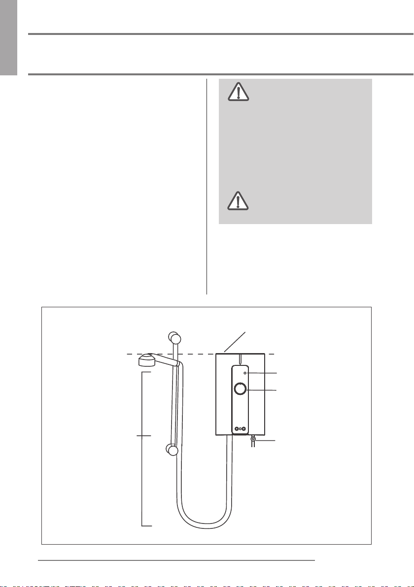
Shower head level must not be higher than the unit.
This appliance is not intended
for use by persons (including
children) with reduced physical,
sensory or mental capabilities, or lack
of experience and knowledge, unless
they have been given supervision or
instruction concerning use of the
appliance by a person responsible for
their safety.
Children should be supervised
to ensure that they do not
play with the appliance.
1.2 The essentials - in brief (Fig 1)
A) Water valve
B) Rotary control for temperature
adjustment
C) “Power” light
D) Shower accessories
C
B
D
2
A
Fig 1
STIEBEL ELTRON
Page 3
1. Operating Instruction for the user and the qualied installer
English
1.3 Important information
The unit is optionally equipped
with an ELSD (Type IS..E only)
It is recommended to test the ELSD
one time per month.
How to test:
Switch on the electrical supply.
Press the Test button, the Trip light
will go on. Press the Reset button.
Warning!
If the Trip light activate after
reset or if the light activate during
shower, never try to x it. Contact
your dealer for a check and repair.
Warning!
If, during a shower , the
water valve is closed, (such as
applying soap to the body), then
valve opened again, high water
temperature may occur, to avoid risk
of scalding, stay any from the shower
head discharge zone momentarily.
The unit must not be put
under pressure. The outlet
of the unit is also used as a vent. A
periodical scale removal is essential
for the function of the shower head.
1.4 Hot water capacity
The hot water capacity depends on
the power of the unit, the cold water
temperature, and the ow volume.
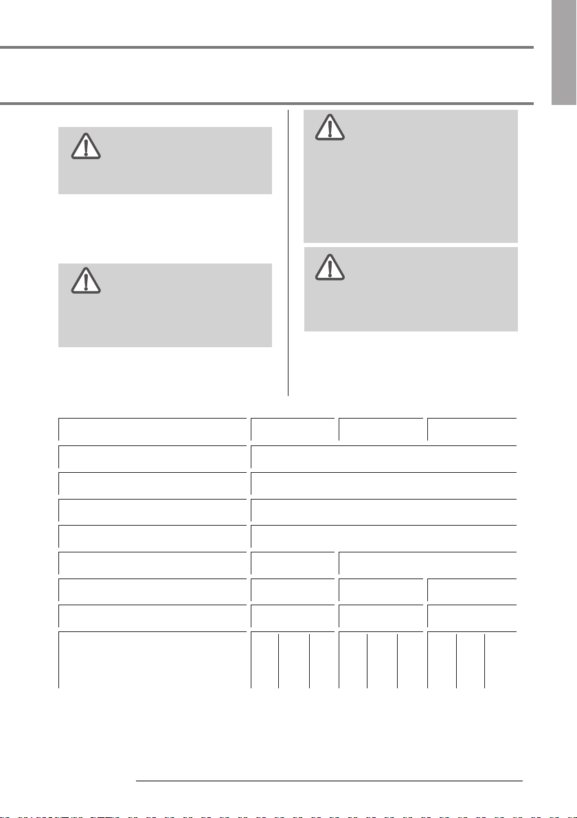
1.5 Technical Data
Type
IS 5-1 E IS 5-2 E IS 7-2 E
Design Open outlet
Min. inlet water pressure MPa(bar)
Max. inlet water pressure MPa(bar) 0.5(5)
0.015(0.15)
Cold water connection G½”
Electrical connection
1/N/PE/AC 115...127V 1/N/PE/AC 208...240V
Recommended circuit breaker 50 A 25 A 30 A
Recommended cable size 8 AWG 12 AWG 10 AWG
Voltage (V)
Rated Power (kW)
Rated current (A)
115 120 127
4.6 5.0 5.6
40 41.7 44
208 220 240
4.1 4.5 5.4
19.5 20.5 22.5
208 220 240
5.3 6.0 7.1
25.7 27.3 29.6
Note:
The cable sizes can only be a guiding value. Always abide by the corresponding
local standards, laws and regulations.
Stiebel Eltron cannot be held liable for any damages.
STIEBEL ELTRON
3
Page 4
English
1. Operating Instruction for the user and the qualied installer
1.6 Important note
All the information in these
Operating and Installation
Instructions must be carefully
followed. These instructions provide
important details regarding the
safety, operation,
maintenance of the unit.
connected to any tab or
tting other than those specied
1.7 Regulations and Provisions
- Regulations of the local power
supply company should be
observed.
- Regulations of the water supply
company should observed
- Technical data.
- Install the unit ush with the wall
- Electrical connection to be secure.
The device must be capable
of being isolated from the
mains, for example by fuses, with an
isolating distance of at least 3.5 mm.
in all poles.
If the supply cord is damaged,
it must be replaced by the
manufacturer, its service agent or
similarly qualied persons in order to
avoid a hazard.
The unit must be earthed
(see circuit diagram). To
protect against water penetration,
the cable seal (2) must be used.
1.8 Installation location
The shower unit is to be
installed in a closed, frost-free
room (disconnected units are to be
The outlet must not be
installation, and
stored in a frost-free location, since
there will always be some water left
in the unit) The IS is to be installed
vertically on a wall (hot water
connection downwards).
1.9 First operation
(Only to be carried out by a qualied
installer)
Before switching on, set the
rotary water valve to “Max”
setting until the pipework and the
unit are free of air.
- Check the operation of the water heater.
- Before switching “ON” set the rotary
temperature to “OFF”
Handing over the unit
Explain to the user how the unit works
and familiarise him or her with its use.
.
- Advise the user about possible
hazards (high water temperature)
- Hand over these instructions, to
be kept in a safe place.
1.10 Care and Maintenance
All that is needed for the housing is a
damp cloth. Do not use any abrasive
cleaning agents or agents containing
solvents.
Maintenance work may only
be carried out by a qualied
installer.
1.11 Service note
When carrying out any work,
isolate the unit from the mains
and shut o the water connection.
- Clean the lter
Disconnect water valve (17), remove
lter (14) and clean. Re-assemble
in reverse order.
4
STIEBEL ELTRON
Page 5
2. Guarantee
English
For guarantees please refer to the
respective terms and conditions of
supply for your country.
The installation, electrical
connection and rst
The company does not accept liability
for failure of any good supplied
which have not been installed and
operated in accordance with the
manufacturer’s instructions.
operation of this appliance should be
carried out by a qualied installer.
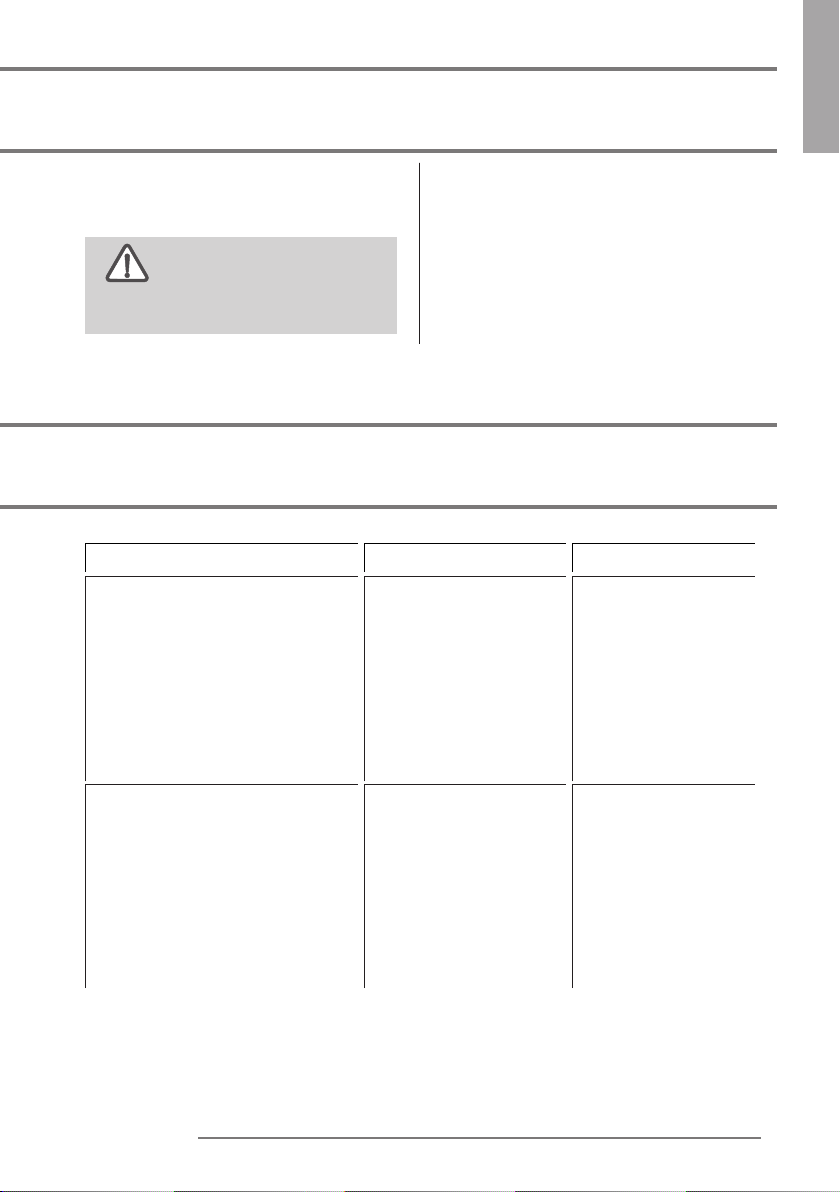
3. Fault elimination for the user
Fault Cause Rectication
No hot water despite ow volume
setting at
“Trip” - light on
The water ow volume
required for the unit to
turn on has not been
reached.
- The shower head is
blocked with
dirt or limescale.
- Flow volume too low.
- ELSD activated
- Clean shower head
or remove limescale.
- Increase ow volume.
- Press “Reset” - button.
The unit is not being switched
on. Electricity supply and ow
available.
STIEBEL ELTRON
The water ow volume
required for the unit to
turn on has not been
reached.
- Filter in the cold water
connection pipe blocked
with dirt.
- Water pressure not
enough
- Clean the lter after
shutting o the cold
water intake.
- Increase mains
pressure
5
Page 6

English
4. Installation Instruction for the qualied installer
350
275.28
18
4 x 35 mm
6 mm
6 mm
210
100.02
min. 4.5 mm
max. 5.5 mm
9
7
100
11
Fig 2
115 mm
50 mm
10
12
Fig 4 Fig 5 Fig 6
Wiring diagram
A
A
Fig 3
13
C
B
D
Type IS 5-1 E
A - Heating Element
B - Electronic control set
C - Double Triac Set
D - Double action Thermostat
D
B
E
F
C
Type IS 5-2 E , IS 7-2 E
A - Heating Element
B - Electronic control set
C - ELSD Circuit
D - Triac Set
E - Thermostat
F - Button Board
G - Current Leakage Sensor
G
Fig 7
6
STIEBEL ELTRON
Page 7

4. Installation Instruction for the qualied installer
4.1 Description of the unit
1 Double action thermostat
2 Cable duct for electrical
connection
3 Power light
4 Rotary control for temperature
adjustment
5Hot water connection for
shower hose
6 Cold water connection
7 Lower fixing hole
8 Position for electrical connection
9 Upper fixing hole
10 Connection cable (Fig 5)
11 Cover securing screw (Fig 3)
12 Depth for mounting screw (Fig 4)
13 Rear wall installation (Fig 6)
14 Combination filter
15 Washer
16 Union nut and washer, provide
by client
17 Water valve
18 ELSD (option)
English
18
9
1
5
8
2
3
4
7
6
14
15
17
16
Fig 8
STIEBEL ELTRON
7
Page 8

English
4. Installation Instruction for the qualied installer
4.2 Installing the unit
1. Flush the cold water pipe
thoroughly.
2. Fit a secure connection cable (10
ensure dimensions are correct).
3. Release cover securing screw (11).
4. Remove cover.
5. Determine the position of the
drill holes and drill the holes.
Insert the wall plugs and screw in
the screws (ensure screw insertion
depth is correct, 12).
6. Feed the connection cable through
the cable seal (2) in the rear wall.
Guide the unit over the wall
securing screws and slide it
downwards (13).
7. Fit the cold water connection.
Connect the water valve (17) with
the lter (14) and the washer (15)
to the cold water inlet of the unit
(6). Tighten the union nut and
washer (16) to the water valve.
8. Straighten the unit and tighten
the screws.
9. Connect the electrical supply.
10. Fit the cover and secure with the
screw.
11. Turn the rotary control (B) to the
left and right (internal setting
lever will engage).
12. Fit the shower accessories to the
unit.
8
STIEBEL ELTRON
Page 9

1. Instrucciones de uso para el usuario y el instalador certicado
1.1 Descripción de la unidad
El calentador de agua instantáneo
sin presión interna de Stiebel Eltron
es un una unidad para calentar
agua para la ducha. La intensidad
de la unidad está controlada
electrónicamente. El ujo se abre
o se cierra usando la válvula de
entrada. La unidad se enciende
cuando el ujo alcanza 1.5-2l/
min. El indicador de “energía”(C) se
enciende cuando la unidad se activa.
Si el control de temperatura (B) se
gira hacia la izquierda, es posible
tomar una ducha fría(la resistencia
no estará activa). La ducha IS cuenta
con un sistema de prevención de
sobrecalentamiento. En caso del
mismo, se desactivará el calor en la
resistencia.
1.2 Información básica- resumen
A Válvula de agua
B Control rotatorio para ajuste
de temperatura
C Indicador de encendido
D Accesorios de ducha
La unidad está equipada de
manera opcional con
un ELSD (sólo modelo IS…E). Se
recomienda probar el ELSD una vez
al mes..
Cómo probar:
Encienda la corriente eléctrica.
Presionar el botón de Test, la luz
indicadora se encenderá. Presionar el
botón de Reset.
Atención!
Si la luz indicadora está activa
después del Reset o si dicha luz está
activa durante el uso de la ducha,
no intente repararla. Contacte con
su distribuidor o técnico para su
comprobación y reparación.
Atención!
Si durante la ducha, la
válvula de agua está cerrada(por
ejemplo, mientras aplicamos el
jabón), y posteriormente se abre,
puede salir agua a temperaturas
muy altas. Para evitar riesgo de
quemarse, apártese de la dicha
momentáneamente.
Español
1.3 Información importante
Esta unidad no debe ser
instalada a presión. La salida
de la unidad también es utilizada
como ventilación. Una eliminación
peródica de residuos de aguas duras
es esencial para el funcionamiento de
la ducha a lo largo del tiempo.
STIEBEL ELTRON
1.4 Cuidado y Mantenimiento
Lo único que necesita para la
cobertura es un trapo húmedo.
No utilice productos de limpieza
abrasivos o que contengan disolventes
Trabajo de mantenimiento
debe ser realizado
únicamente por un instalador
cualicado.
9
Page 10

Español
1. Instrucciones de uso para el usuario y el instalador certicado
1.5 Capacidad de agua caliente
La capacidad de agua caliente
depende de la potencia de la unidad,
de la temperatura del agua entrante
y del volumen del ujo entrante.
- Este calentador no
está diseñado para su uso
por personas(incluidos niños) con
experiencia o conocimiento, a no ser
que hayan recibido instrucciones para
el uso de este aparato por la persona
responsable de su seguridad.
- Los niños deben ser
supervisados para asegurarse
de que no juegan con la unidad.
capaciadades físicas, sensoriales o
mentales reducidas, o insuciente
1.6 Datos Técnicos
(Se aplica la información en la placa de datos de la unidad)
Tipo IS 5-1 E IS 5-2 E IS 7-2 E
Diseño Sistema abierto
Min. la presión del agua de entrada MPa (bar)
Max. la presión del agua de entrada MPa (bar)
Conexión de agua ( Ø Tuberia) G ½“
0.015(0.15)
0.5(5)
Conexión eléctrica
Tamaño Mínimo Requerido
del Interruptor Auto. “Breaker”
Cable AWG Cobre
Voltaje (V)
Vatios (kW)
Amperaje (A)
1/N/PE/AC 115...127V 1/N/PE/AC 208...240V
50 A 25 A 30 A
8 AWG 12 AWG 10 AWG
115 120 127
4.6 5.0 5.6
40 41.7 44
208 220 240
4.1 4.5 5.4
19.5 20.5 22.5
Los tamaños
de cables son únicamente valores orientativos. Se deben tener en cuenta los
correspondientes estándares, normas, leyes y reglamentos locales. Stiebel Eltron
no se hace responsable de posibles daños y perjuicios.
10
208 220 240
5.3 6.0 7.1
25.7 27.3 29.6
STIEBEL ELTRON
Page 11

2. Garantía
Español
Para las garantías, consulte los
respectivos términos y condiciones
de la oferta de su país.
La empresa no se hace responsable
del fallo de cualquier mercancía
suministrada que no se haya
instalado u operado de acuerdo con
La instalación, la conexión
las instrucciones del fabricante.
eléctrica y la primera
operación de este aparato debe
ser realizada por un instalador
autorizado.
3. Identicación y resolución de incidencias
Motivo Causa Solución
No hay agua caliente a pesar
de que el control rotatorio esta
situado al máximo a la derecha.
“Trip” - light on
No hay suciente ujo
para activar la unidad
- La ducha está
bloqueada con
impurezas de aguas
duras.
- ELSD activado
- Limpiar la cabeza de
ducha de impurezas
- Presionar botón de
“Reset”.
La unidad no se enciende.
Conexión eléctrica y ujo
disponible.
STIEBEL ELTRON
El volumen de ujo de
agua requerido para
encender la unidad no
se ha alcanzado
- Filtro en la entrada de
agua fría está
bloqueado con
impurezas.
- Presión de agua
insuciente
- Limpiar el ltro
después de cortar la
entrada de agua fría.
- Incrementar la
presión del sistema
11
Page 12

Español
4. Instrucciones de instalación para el usuario y el instalador cualificado
La ducha no debe estar a una altura mayor que la unidad.
C
B
10
115 mm
50 mm
11
D
13
Modelo IS...E Modelo IS...
A
4 x 35 mm
6 mm
6 mm
A
min. 4.5 mm
max. 5.5 mm
12
9
210
350
275.28
7
18
100.02
A
100
12
D
E
G
F
C
B
C
B
D
A - Resistencia
B - Set de control electrónico
C - Circuito ELSD
D - Set de Triac
E - Termostato
F - Tablero de botones
G - Sensor de corriente de fuga
A - Resistencia
B - Set de control electrónico
C - Set de Triac
D - Termostato
STIEBEL ELTRON
Page 13

4. Instrucciones de instalación para el usuario y el instalador cualificado
4.1 Información técnica
1 Termostato de doble acción
2 Canal de cableado para conexión
eléctrica
3 Indicador de encendido
4 Control rotatorio para el ajuste
de la temperatura
5 Conexión de agua caliente para
la manguera de ducha
6 Toma de agua fría
7 Agujero de jación inferior
8 Posición para la conexión eléctrica
9 Agujero de jación superior
10 Conexión del cable
11 Tornillo de jación de la tapa
12 Profundidad para tornillos de montaje
13 Instalación para la pared trasera
14 Combinación ltro / sello
15 Arandela
16 Tuerca de unión y arandela,
proporcionada por el cliente
17 Válvula de agua
18 ELSD (opcional)
Español
STIEBEL ELTRON
18
9
1
5
8
2
3
4
7
6
14
15
17
16
13
Page 14

Español
4. Instrucciones de instalación para el usuario y el instalador cualificado
4.2 Reglamentos y disposiciones
- Reglamento de la empresa de
suministro eléctrico local debe
ser observado
- Reglamento de la empresa
de suministro de agua debe ser
observado.
- Reglamento de la empresa de
suministro de agua deben ser
observados.
- Datos técnicos.
- Instale la unidad a ras con la pared.
- La conexión eléctrica es segura.
El dispositivo debe ser capaz
de ser aislado de la red, por
ejemplo por medio de fusibles, con
una distancia de aislamiento de al
menos 3,5 mm, en todos los polos.
La unidad debe estar
conectada a tierra (ver
esquema). Para proteger contra la
penetración de agua, el sello del cable
(2) debe ser utilizado.
4.4 Lugar de montaje
La unidad de ducha se debe
instalar en un sistema cerrado,
en una habitación libre de escarcha
(unidades desconectadas deben ser
almacenadas en un lugar libre de
escarcha, ya que siempre habrá algo
de agua en la unidad), el IS es para ser
instalado verticalmente en una muro
(conexión de agua caliente hacia abajo).
4.3 Nota importante
Toda la información en este
manual de instrucciones y la
instalación deben seguirse
cuidadosamente. Estas instrucciones
proporcionan detalles importantes
con respecto a la seguridad, operación,
instalación y mantenimiento de la unidad.
14
STIEBEL ELTRON
Page 15

4. Instrucciones de instalación para el usuario y el instalador cualificado
Español
4.5 Instalación del calentador
1. Purgue la tubería de agua fría a
fondo.
2. Coloque un cable de conexión
segura (10 asegurar que
dimensiones son correctas).
3. Soltar tornillo de jación de la
tapa (11).
4. Quite la cubierta.
5. Determinar la posición de los
agujeros de perforación y perforar
los agujeros. Inserte los tacos y
atornille los tornillos asegurar la
profundidad de inserción del
tornillo es correcta, 12).
6. Alimentar el cable de conexión
a través de la junta de cable (2) en
la pared trasera. Guíe la unidad
sobre la pared sobre los tornillos de
jación y deslice hacia abajo (13).
7. Coloque la conexión de agua
fría. Conectar la válvula de agua
(17) con el ltro (14) y la arandela
(15) a la entrada de agua fría de
la unidad (6). Apretar la tuerca de
unión y la arandela (16) en la
válvula de agua.
8. Enderece la unidad y apriete los
tornillos.
9. Conecte el suministro eléctrico.
10. Coloque la cubierta y asegúrela
con el tornillo.
11. Girar el control giratorio (B) a la
izquierda y la derecha (palanca
de ajuste interno se acoplará).
12. Montar los accesorios de ducha a
la unidad.
La salida no debe estar
conectada a ninguno de los
accesorios que no sean los especicados.
4.6 Primera operación
(Sólo para ser llevada a cabo por
un instalador calicado)
Antes de poner en
funcionamiento, ajustar la
válvula de agua giratorio en “Max”
hasta que las tuberías y la unidad estén
libres de aire.
- Comprobar el funcionamiento del
calentador de agua.
- Antes de poner en “ON”, ajuste la
temperatura giratoria en “OFF”
Entrega de la unidad
Explique al usuario cómo funciona la
unidad y familiarice a él o ella con su
uso.
- Informar al usuario sobre los posibles
peligros (alta temperatura del agua)
- Entregar estas instrucciones, que
deben mantenerse en un lugar seguro.
4.7 Nota de Servicio
En el desempeño de
cualquier trabajo, aislar la
unidad de la red eléctrica y cierre la
toma de agua.
- Limpie el ltro
Desconecte la válvula de agua (17),
quite el ltro (14) y límpielo. Vuelva a
montar en el orden inverso.
STIEBEL ELTRON
15
Page 16

Size:A5
Material: Green read paper 75 g.
Plastic bag : 7 x 11 INCH
Part no. 7901-315405
Part name : OPERATING INSTRUCTION IS (En-Sp)
Rev.00
Product code : IS 5-1 E :234257 / IS 5-2 E : 234258 / IS 7-2 E : 234260
 Loading...