

Page 1
BE
DIENUNG UND INSTALLATION
OPERATION AND INSTALLATION
UTILISATION ET INSTALLATION
Elektronisch ge
regelter Kompakt Durchlauferhitzer | Electronically controlled
instantaneous water heater | Chauffe-eau instantané compact à régulation
électronique
» DCE 11/13
» DCE 11/13 H
» DCE 11/13 RC
1
+
-
2
°C
40
50
60
30
20
°C
40
50
60
30
20
Page 2

2 |DCE 11/13| DCE 11/13 RC| DCE 11/13 H www.stiebel-eltron.com
INHALT | BESONDERE HINWEISE
BESONDERE HINWEISE
BEDIENUNG
1. Allgemeine Hinweise ����������������������������������������3
1.1 Sicherheitshinweise ��������������������������������������������� 3
1.2 Andere Markierungen in dieser Dokumentation ���������� 3
1.3 Maßeinheiten ����������������������������������������������������� 3
2. Sicherheit �����������������������������������������������������3
2.1 Bestimmungsgemäße Verwendung ������������������������� 3
2.2 Allgemeine Sicherheitshinweise ������������������������������ 3
2.3 Prüfzeichen ������������������������������������������������������� 4
3. Gerätebeschreibung �����������������������������������������4
4. Einstellungen �������������������������������������������������4
4.1 DCE11/13 | DCE11/13H �������������������������������������� 4
4.2 DCE11/13RC ����������������������������������������������������� 4
4.3 Verbrühschutz/ Temperaturbegrenzung ������������������� 5
4.4 Nach Unterbrechung der Wasserversorgung �������������� 5
5. Reinigung, Pflege und Wartung ����������������������������5
6. Problembehebung �������������������������������������������6
INSTALLATION
7. Sicherheit �����������������������������������������������������7
7.1 Allgemeine Sicherheitshinweise ������������������������������ 7
7.2 Vorschriften, Normen und Bestimmungen ����������������� 7
8. Gerätebeschreibung �����������������������������������������7
8.1 Lieferumfang ����������������������������������������������������� 7
8.2 Zubehör ������������������������������������������������������������ 7
9. Vorbereitungen �����������������������������������������������7
9.1 Montageort ������������������������������������������������������� 8
9.2 Mindestabstände ������������������������������������������������ 8
10. Montage �������������������������������������������������������9
10.1 Standardmontage������������������������������������������������ 9
11. Inbetriebnahme �������������������������������������������� 10
11.1 Erstinbetriebnahme �������������������������������������������� 10
11.2 Übergabe des Gerätes ����������������������������������������� 10
11.3 Wiederinbetriebnahme ���������������������������������������� 10
12. Außerbetriebnahme ��������������������������������������� 10
13. Montage-Alternativen ������������������������������������� 10
13.1 Wählbare Anschlussleistung ��������������������������������� 10
13.2 Verbrühschutz/ Temperaturbegrenzung ������������������11
13.3 Umbau Elektroanschluss unten ������������������������������ 11
14. Störungsbehebung ����������������������������������������� 11
15. Wartung ����������������������������������������������������� 13
16. Technische Daten ������������������������������������������� 14
16.1 Maße und Anschlüsse ����������������������������������������� 14
16.2 Elektroschaltplan ����������������������������������������������� 14
16.3 Einsatzbereiche / Umrechnungstabelle �������������������� 14
16.4 Druckverluste ���������������������������������������������������� 15
16.5 Störfallbedingungen �������������������������������������������15
16.6 Landesspezifische Zulassungen und Zeugnisse ���������� 15
16.7 Angaben zum Energieverbrauch ����������������������������15
16.8 Datentabelle ����������������������������������������������������� 15
BESONDERE HINWEISE
- Das Gerät kann von Kindern ab 3 Jahren sowie
von Personen mit verringerten physischen, sensorischen oder mentalen Fähigkeiten oder Mangel an Erfahrung und Wissen benutzt werden,
wenn sie beaufsichtigt werden oder bezüglich
des sicheren Gebrauchs des Gerätes unterwiesen
wurden und die daraus resultierenden Gefahren
verstanden haben. Kinder dürfen nicht mit dem
Gerät spielen. Reinigung und Benutzer-Wartung
dürfen nicht von Kindern ohne Beaufsichtigung
durchgeführt werden.
- Die Armatur kann während des Betriebs eine
Temperatur von über 60 °C annehmen. Bei
Auslauftemperaturen größer 43 °C besteht
Verbrühungsgefahr.
- Das Gerät muss über eine Trennstrecke von mindestens 3 mm allpolig vom Netzanschluss getrennt werden können.
- Das Netzanschlusskabel darf bei Beschädigung
oder Austausch nur durch einen vom Hersteller
berechtigten Fachhandwerker mit dem originalen
Ersatzteil ersetzt werden.
- Befestigen Sie das Gerät wie in Kapitel „Installation/ Montage“ beschrieben.
- Beachten Sie den maximalen zulässigen Druck
(siehe Kapitel „Installation/ Technische Daten/
Datentabelle“).
- Entleeren Sie das Gerät wie in Kapitel „Installation / Wartung / Gerät entleeren“ beschrieben.
KUNDENDIENST UND GARANTIE
UMWELT UND RECYCLING
MONTAGESCHABLONE IM MITTELTEIL DIESER ANLEITTUNG
Page 3
BEDIENUNG
Allgemeine Hinweise
DEUTSCH
www.stiebel-eltron.com DCE 11/13| DCE 11/13 RC| DCE 11/13 H | 3
BEDIENUNG
1. Allgemeine Hinweise
Das Kapitel „Bedienung“ richtet sich an den Gerätebenutzer und
den Fachhandwerker.
Das Kapitel „Installation“ richtet sich an den Fachhandwerker.
Hinweis
Lesen Sie diese Anleitung vor dem Gebrauch sorgfältig
durch und bewahren Sie sie auf.
Geben Sie die Anleitung ggf. an einen nachfolgenden
Benutzer weiter.
1.1 Sicherheitshinweise
1.1.1 Aufbau von Sicherheitshinweisen
SIGNALWORT Art der Gefahr
Hier stehen mögliche Folgen bei Nichtbeachtung des
Sicherheitshinweises.
Hier stehen Maßnahmen zur Abwehr der Gefahr.
1.1.2 Symbole, Art der Gefahr
Symbol Art der Gefahr
Verletzung
Stromschlag
Verbrennung
(Verbrennung, Verbrühung)
1.1.3 Signalworte
SIGNALWORT Bedeutung
GEFAHR Hinweise, deren Nichtbeachtung schwere Verletzungen
oder Tod zur Folge haben.
WARNUNG Hinweise, deren Nichtbeachtung schwere Verletzungen
oder Tod zur Folge haben kann.
VORSICHT Hinweise, deren Nichtbeachtung zu mittelschweren oder
leichten Verletzungen führen kann.
1.2 Andere Markierungen in dieser Dokumentation
Hinweis
Hinweise werden durch horizontale Linien ober- und unterhalb des Textes begrenzt. Allgemeine Hinweise werden mit dem nebenstehenden Symbol gekennzeichnet.
Lesen Sie die Hinweistexte sorgfältig durch.
Symbol
Sachschaden
(Geräte-, Folgen-, Umweltschaden)
Geräteentsorgung
Dieses Symbol zeigt Ihnen, dass Sie etwas tun müssen.
Die erforderlichen Handlungen werden Schritt für Schritt
beschrieben.
1.3 Maßeinheiten
Hinweis
Wenn nicht anders angegeben, ist die verwendete Maßeinheit Millimeter.
2. Sicherheit
2.1 Bestimmungsgemäße Verwendung
Das Gerät ist für den Einsatz im häuslichen Umfeld vorgesehen.
Es kann von nicht eingewiesenen Personen sicher bedient werden. In nicht häuslicher Umgebung, z.B. im Kleingewerbe, kann
das Gerät ebenfalls verwendet werden, sofern die Benutzung in
gleicher Weise erfolgt.
Das Gerät dient zur Erwärmung von Trinkwasser oder zur Nacherwärmung von vorgewärmtem Wasser. Das Gerät ist für eine Küchenspüle oder ein Handwaschbecken bestimmt.
Eine andere oder darüber hinausgehende Benutzung gilt als nicht
bestimmungsgemäß. Zum bestimmungsgemäßen Gebrauch gehört auch das Beachten dieser Anleitung sowie der Anleitungen
für eingesetztes Zubehör.
2.2 Allgemeine Sicherheitshinweise
WARNUNG Verbrennung
Die Armatur kann während des Betriebs eine Temperatur
von über 60°C annehmen.
Bei Auslauftemperaturen größer 43°C besteht Verbrühungsgefahr.
!
WARNUNG Verletzung
Das Gerät kann von Kindern ab 3 Jahren sowie von Personen mit verringerten physischen, sensorischen oder
mentalen Fähigkeiten oder Mangel an Erfahrung und
Wissen benutzt werden, wenn sie beaufsichtigt werden
oder bezüglich des sicheren Gebrauchs des Gerätes unterwiesen wurden und die daraus resultierenden Gefahren verstanden haben. Kinder dürfen nicht mit dem Gerät
spielen. Reinigung und Benutzer-Wartung dürfen nicht
von Kindern ohne Beaufsichtigung durchgeführt werden.
WARNUNG Stromschlag
Ein beschädigtes Anschlusskabel darf nur der Fachhandwerker austauschen. Dadurch vermeiden Sie eine mögliche Gefährdung.
!
Sachschaden
Schützen Sie das Gerät und die Armatur vor Frost.
!
!
Page 4
BEDIENUNG
Gerätebeschreibung
4 |DCE 11/13| DCE 11/13 RC| DCE 11/13 H www.stiebel-eltron.com
2.3 Prüfzeichen
Siehe Typenschild am Gerät.
Landesspezifische Zulassungen und Zeugnisse: Deutschland
Für die Geräte ist aufgrund der Landesbauordnungen ein allgemeines bauaufsichtliches Prüfzeugnis zum Nachweis der Verwendbarkeit hinsichtlich des Geräuschverhaltens erteilt.
DIN 4109
P-IX 16726/I
3. Gerätebeschreibung
Der elektronisch geregelte Kompakt-Durchlauferhitzer hält die
Auslauftemperatur unabhängig von der Zulauftemperatur bis zur
Leistungsgrenze konstant.
Das Gerät erwärmt das Wasser direkt an der Entnahmestelle, sobald Sie das Warmwasserventil an der Armatur öffnen. Durch
kurze Leitungswege entstehen geringe Energie- und Wasserverluste.
Einschaltmenge siehe Kapitel „Installation/ Technische Daten/
Datentabelle“.
Die Warmwasserleistung hängt von der Kaltwassertemperatur,
der Heizleistung, der Durchflussmenge und der eingestellten
Wunschtemperatur ab.
Warmwasser-Temperatur
Die Warmwasser-Auslauftemperatur können Sie stufenlos einstellen.
Heizsystem
Das Blankdraht-Heizsystem ist für kalkarme und kalkhaltige Wässer geeignet. Das Heizsystem ist gegen Verkalkung weitgehend
unempfindlich. Das Heizsystem sorgt für eine schnelle und effiziente Bereitstellung von Warmwasser.
Hinweis
Das Gerät ist mit einer Lufterkennung ausgestattet, die
eine Beschädigung des Heizsystems weitgehend verhindert. Gelangt während des Betriebes Luft in das Gerät,
schaltet die Heizleistung automatisch für eine Minute aus
und das Heizsystem ist geschützt.
4. Einstellungen
4.1 DCE11/13 | DCE11/13H
Bedienung
°C
40
50
60
30
20
D0000039989
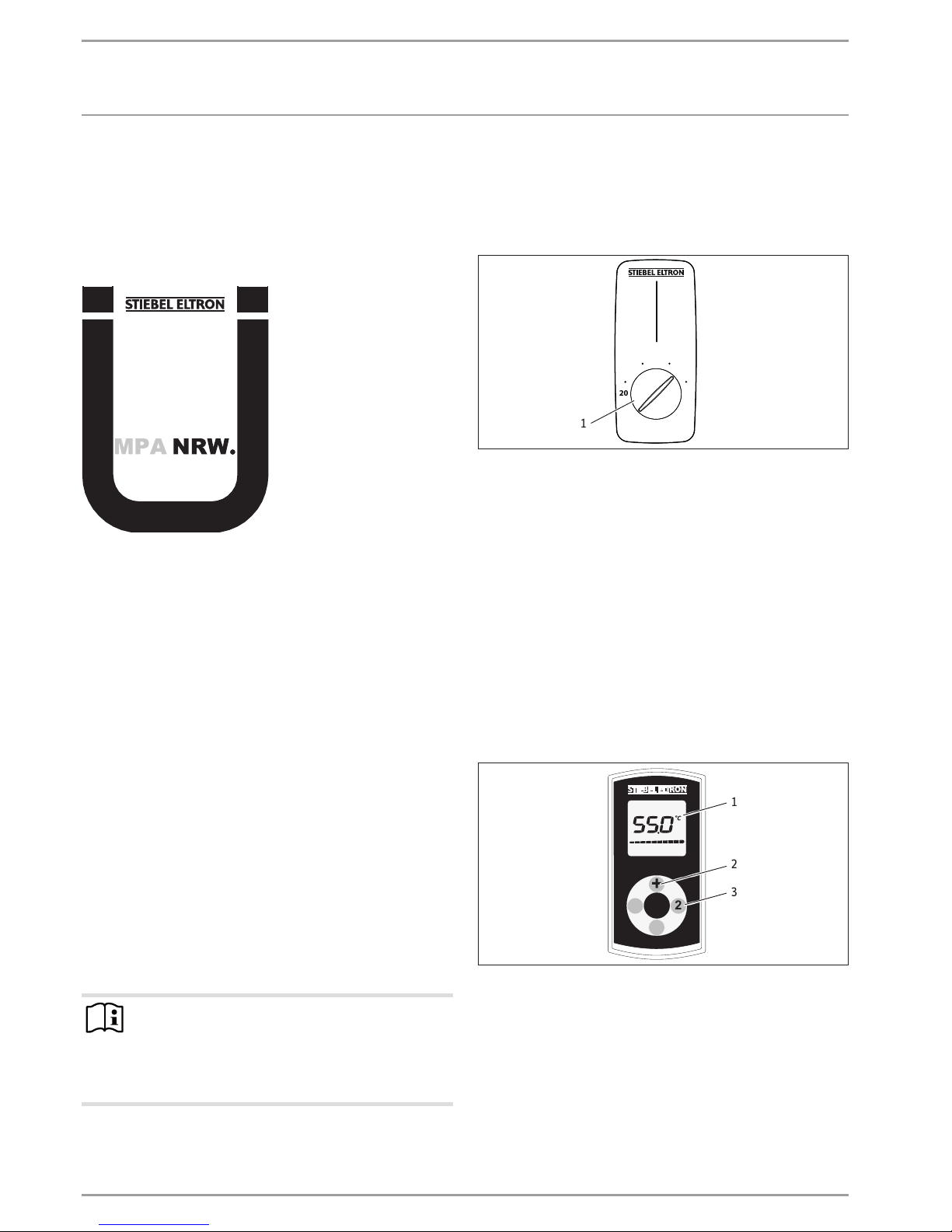
1
1 Temperatur-Einstellknopf, Temperatureinstellung
20°C- 60°C
4.2 DCE11/13RC
Mit der Funk-Fernbedienung können Sie die Temperatureinstellung per Funk ändern. Die eingestellte Temperatur erscheint auf
dem Display der Funk-Fernbedienung.
Die mitgelieferte Funk-Fernbedienung ist beim Empfängermodul
angemeldet. Nur eine angemeldete Funk-Fernbedienung kann die
Einstellungen am Gerät ändern.
Die Reichweite der Funkstrecke reduziert sich durch Hindernisse
zwischen dem Gerät und der Funk-Fernbedienung.
Sie können die Funk-Fernbedienung mit der zum Lieferumfang
gehörenden Wandhalterung an einem beliebigen Ort montieren.
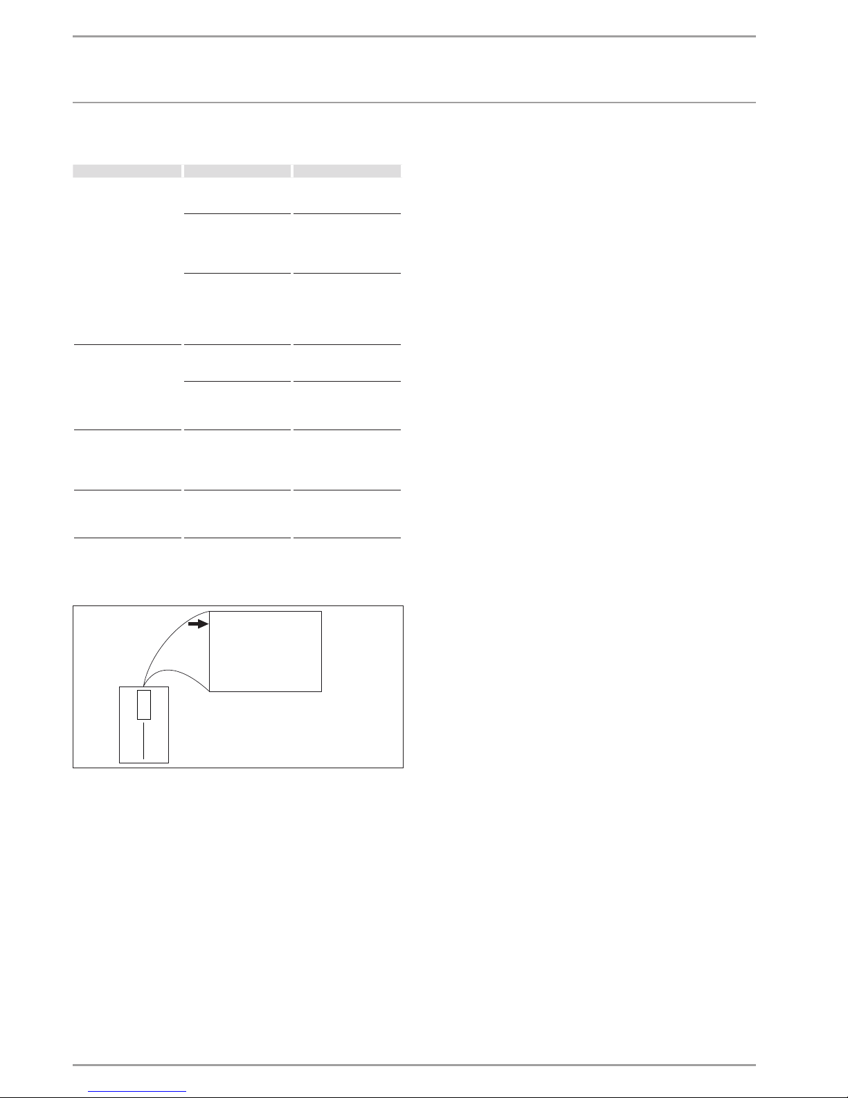
Bedienung
1
+
-
2
D0000039990
2
1
3
1 Display
2 Temperatureinstellung 20°C - 60°C in 0,5°C- Schritten mit
den Tasten „+“ und „-“
3 Speichertasten „1“ und „2“
Die Funk-Fernbedienung befindet sich im Normalfall im stromspa-
renden Modus, dabei ist das Display ausgeschaltet. Durch Drücken
einer beliebigen Taste aktivieren Sie die Funk-Fernbedienung, die
Temperaturanzeige erscheint. Der Laufbalken im Display signalisiert die Datenübertragung zum Gerät.
Wenn innerhalb von 10Sekunden keine Betätigung einer Taste
erfolgt, schaltet die Funk-Fernbedienung automatisch wieder in
den stromsparenden Modus.
Page 5
BEDIENUNG
Reinigung, Pege und Wartung
DEUTSCH
www.stiebel-eltron.com DCE 11/13| DCE 11/13 RC| DCE 11/13 H | 5
Die gewählte Temperatur wird auch im Stromsparmodus beibehalten.
Speichertastenbelegung
Wählen Sie eine Wunschtemperatur.
Drücken Sie 2Sekunden die Speichertaste „1“ oder „2“. Zur
Bestätigung blinkt die Temperaturanzeige 1x.
Sie können das Heizsystem des Gerätes ausschalten (Dis-
play-Anzeige OFF). Drücken Sie zum Ausschalten die Taste
„-“ 1x, ausgehend von der Einstellung 20°C.
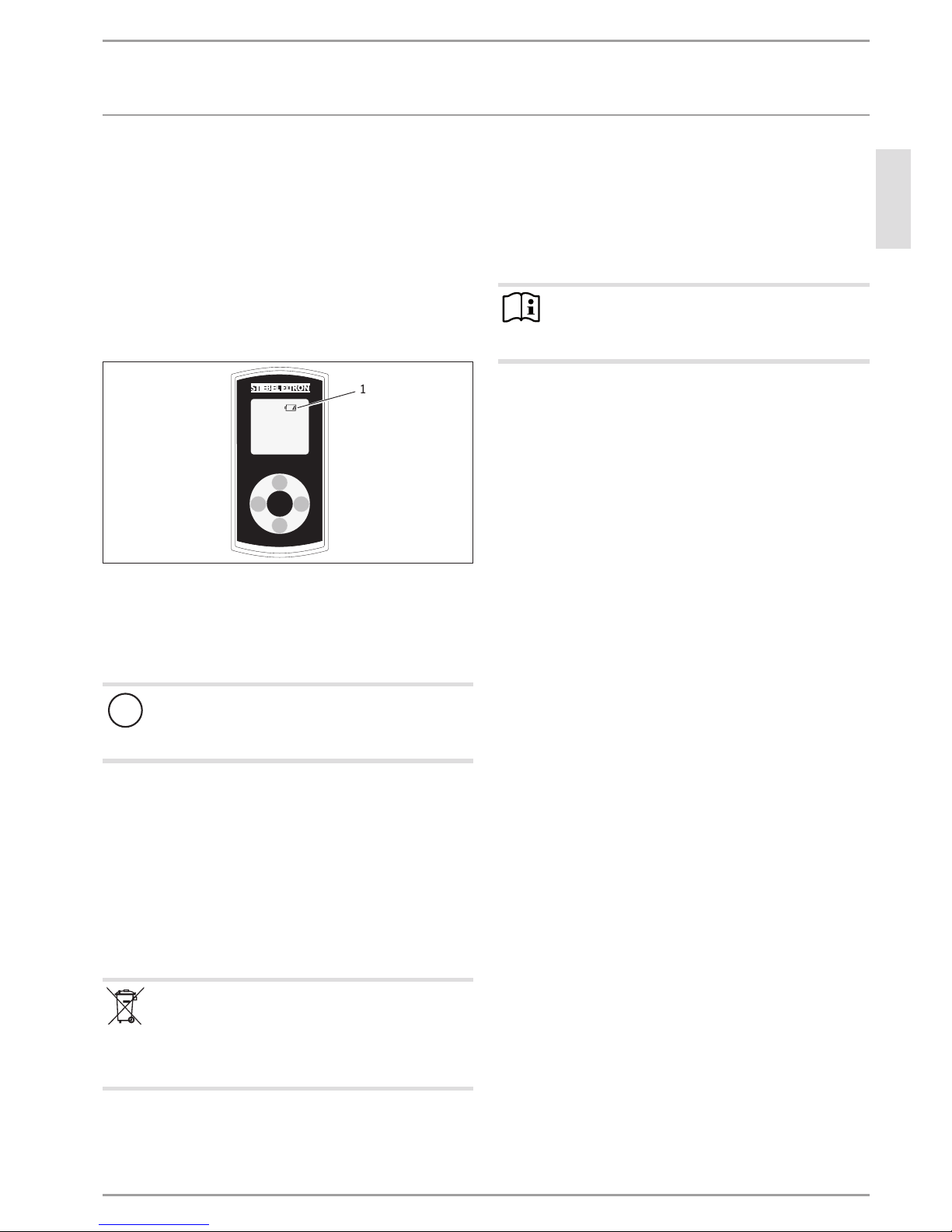
Batteriewechsel
1
+
-
2
D0000047484
1
1 Symbol Batteriewechsel
Wenn das Batteriesymbol aufleuchtet, wechseln Sie die Batterie
der Funk-Fernbedienung. Ein Batteriewechsel kann auch notwendig werden, wenn die Temperatureinstellungen nicht beim
Gerät ankommen und/oder die Reichweite der Funkstrecke sich
verkleinert.
!
Sachschaden
Entfernen Sie die verbrauchte Batterie.
Für Schäden durch eine ausgelaufene Batterie haften wir
nicht.
Öffnen Sie das Gehäuse der Funk-Fernbedienung, indem Sie
die 4 Schrauben an der Unterseite der Funk-Fernbedienung
lösen.
Wechseln Sie die Batterie, Bauform CR2032, aus. Der Einsatz
von NiCd-Akkus ist nicht zulässig. Achten Sie auf die korrekte
Polung der Batterie (+ oben).
Drücken Sie das Gehäuse wieder zusammen und schrauben
die 4 Schrauben wieder ein. Bei der Montage des Gehäuses
dürfen Sie die umlaufende Dichtung nicht beschädigen.
Während des Batteriewechsels bleiben die gespeicherten Werte
für die Tasten „1 „und „2“ erhalten.
Batterie entsorgen
Batterien dürfen Sie nicht im Hausmüll entsorgen. Altbatterien enthalten Schadstoffe, die der Umwelt und
Gesundheit schaden. Verbrauchte Batterien müssen Sie
beim Handel oder einer Sammelstelle für Sonderstoffe
abgeben.
4.3 Verbrühschutz/ Temperaturbegrenzung
Bei der Aktivierung des Verbrühschutzes können Sie die Warmwasser-Temperatur nur von 20°C bis 43°C einstellen.
Höhere Temperatureinstellungen werden nicht ausgeführt.
Verwenden Sie den Verbrühschutz z.B. in Kindergärten, Kranken-
häusern, Seniorenheimen usw.
Hinweis
Der Fachhandwerker darf Ihnen den Verbrühschutz im
Gerät aktivieren (siehe Kapitel „Installation/ Montage-Alternativen/ Verbrühschutz/ Temperaturbegrenzer“).
4.4 Nach Unterbrechung der Wasserversorgung
Siehe Kapitel „Installation/ Inbetriebnahme/ Wiederinbetriebnahme“.
5. Reinigung, Pflege und Wartung
Verwenden Sie keine scheuernden oder anlösenden Reini-
gungsmittel. Zur Pflege und Reinigung des Gerätes genügt
ein feuchtes Tuch.
Kontrollieren Sie regelmäßig die Armaturen. Kalk an den
Armaturausläufen können Sie mit handelsüblichen Entkalkungsmitteln entfernen.
Lassen Sie die elektrische Sicherheit am Gerät regelmäßig
von einem Fachhandwerker prüfen.
Page 6
BEDIENUNG
Problembehebung
6 |DCE 11/13| DCE 11/13 RC| DCE 11/13 H www.stiebel-eltron.com
6. Problembehebung
Problem Ursache Behebung
Das Gerät schaltet trotz
voll geöffnetem Warmwasserventil nicht ein.
Am Gerät liegt keine
Spannung an.
Prüfen Sie die Sicherung
in der Hausinstallation.
Die Durchflussmenge ist
zu gering. Der Strahlregler in der Armatur
ist verkalkt oder verschmutzt.
Reinigen und / oder entkalken Sie den Strahlregler oder erneuern Sie den
Spezial-Strahlregler.
Die Wasserversorgung ist
unterbrochen.
Entlüften Sie das Gerät
und die Kaltwasser-Zulaufleitung (siehe Kapitel
„Installation/Inbetriebnahme/ Wiederinbetriebnahme“).
Die Wunschtemperatur
wird nicht erreicht.
Der interne Verbrühschutz ist aktivier t.
Lassen Sie den Verbrühschutz vom Fachhandwerker deaktivieren.
Das Gerät heizt nicht
mehr, die Kaltwasser-Zulauftemperatur ist
>55°C.
Verringern Sie die Kaltwasser-Zulauftemperatur.
„Con“ erscheint gelegentlich auf dem Display.
Die Funk-Fernbedienung
befindet sich außerhalb
der Reichweite.
Verringern Sie den
Abstand von Funk-Fernbedienung zum Gerät.
Senden Sie erneut den
Temperaturwunsch.
„Con“ erscheint häufig
auf dem Display.
Batterie ist am Ende der
Kapazität.
Wechseln Sie die Batterie
(siehe Kapitel „Bedienung / Gerätebeschreibung / Batteriewechsel“).
Können Sie die Ursache nicht beheben, rufen Sie den Fachhandwerker. Zur besseren und schnelleren Hilfe teilen Sie ihm die
Nummer vom Typenschild mit (000000-0000-000000).
Nr.: 000000-0000-000000
D0000040351
Page 7
DEUTSCH
www.stiebel-eltron.com DCE 11/13| DCE 11/13 RC| DCE 11/13 H | 7
INSTALLATION
Sicherheit
INSTALLATION
7. Sicherheit
Die Installation, Inbetriebnahme sowie Wartung und Reparatur
des Gerätes darf nur von einem Fachhandwerker durchgeführt
werden.
7.1 Allgemeine Sicherheitshinweise
Wir gewährleisten eine einwandfreie Funktion und Betriebssicherheit nur, wenn das für das Gerät bestimmte Original-Zubehör und
die originalen Ersatzteile verwendet werden.
!
Sachschaden
Beachten Sie die max. zulässige Zulauftemperatur (siehe
Kapitel „Installation/ Technischen Daten/ Datentabelle“).
Bei höheren Temperaturen kann das Gerät beschädigt
werden. Mit einer Zentral-Thermostatarmatur (siehe
Kapitel „Installation/ Gerätebeschreibung/ Zubehör“)
können Sie die Zulauftemperatur begrenzen.
7.2 Vorschriften, Normen und Bestimmungen
Hinweis
Beachten Sie alle nationalen und regionalen Vorschriften
und Bestimmungen.
Der spezifische elektrische Widerstand des Wassers darf nicht
kleiner sein als auf dem Typenschild angegeben. Bei einem Wasser-Verbundnetz müssen Sie den niedrigsten elektrischen Widerstand des Wassers berücksichtigen (siehe Kapitel „Installation/
Technischen Daten/ Datentabelle“). Den spezifischen elektrischen
Widerstand oder die elektrische Leitfähigkeit des Wassers erfahren Sie bei Ihrem Wasserversorgungs-Unternehmen.
8. Gerätebeschreibung
8.1 Lieferumfang
Mit dem Gerät werden geliefert:
- Stopfen für Kabeldurchführung
- Montageschablone, im Mittelteil dieser Anleitung
- Anschlussschlauch 3/8, 500mm lang, mit Dichtungen*
- T-Stück 3/8*
* nur bei DCE 11/13 und DCE 11/13 RC für den Anschluss als druckfestes Gerät
8.2 Zubehör
Lastabwurfrelais
Eine Vorrangschaltung kann mit einem elektronischen Lastabwurfrelais ermöglicht werden, z.B. um einen zweiten Durchlauferhitzer vom Stromnetz zu trennen.
Der Ansprechstrom des Lastabwurfrelais muss ≤2A sein. Der
Anschluss erfolgt an der mittleren Klemme „L“.
Drucklose Armaturen
- WEN-Sensor-Armatur für den Waschtisch
- MEK Einhebel-Mischarmatur
- WKM Zweigriff-Mischarmatur
Druckfeste Armatur
- WEH-Sensor-Armatur für den Waschtisch
- MEKD-Einhebel-Mischarmatur für Übertisch
ZTA 3/4 – Zentral Thermostatarmatur
Die Thermostatarmatur ist für die zentrale Vormischung, z.B. zum
Betrieb des Durchlauferhitzers mit einer Solaranlage.
9. Vorbereitungen
Spülen Sie die Wasserleitung gut durch.
Wasserinstallation
Ein Sicherheitsventil ist nicht notwendig.
Armaturen
Verwenden Sie geeignete Armaturen (siehe Kapitel „Installa-
tion/ Gerätebeschreibung/ Zubehör“).
Page 8
8 |DCE 11/13| DCE 11/13 RC| DCE 11/13 H www.stiebel-eltron.com
INSTALLATION
Vorbereitungen
9.1 Montageort
Montieren Sie das Gerät immer senkrecht, in einem frostfreien
Raum und in der Nähe der Entnahmestelle.
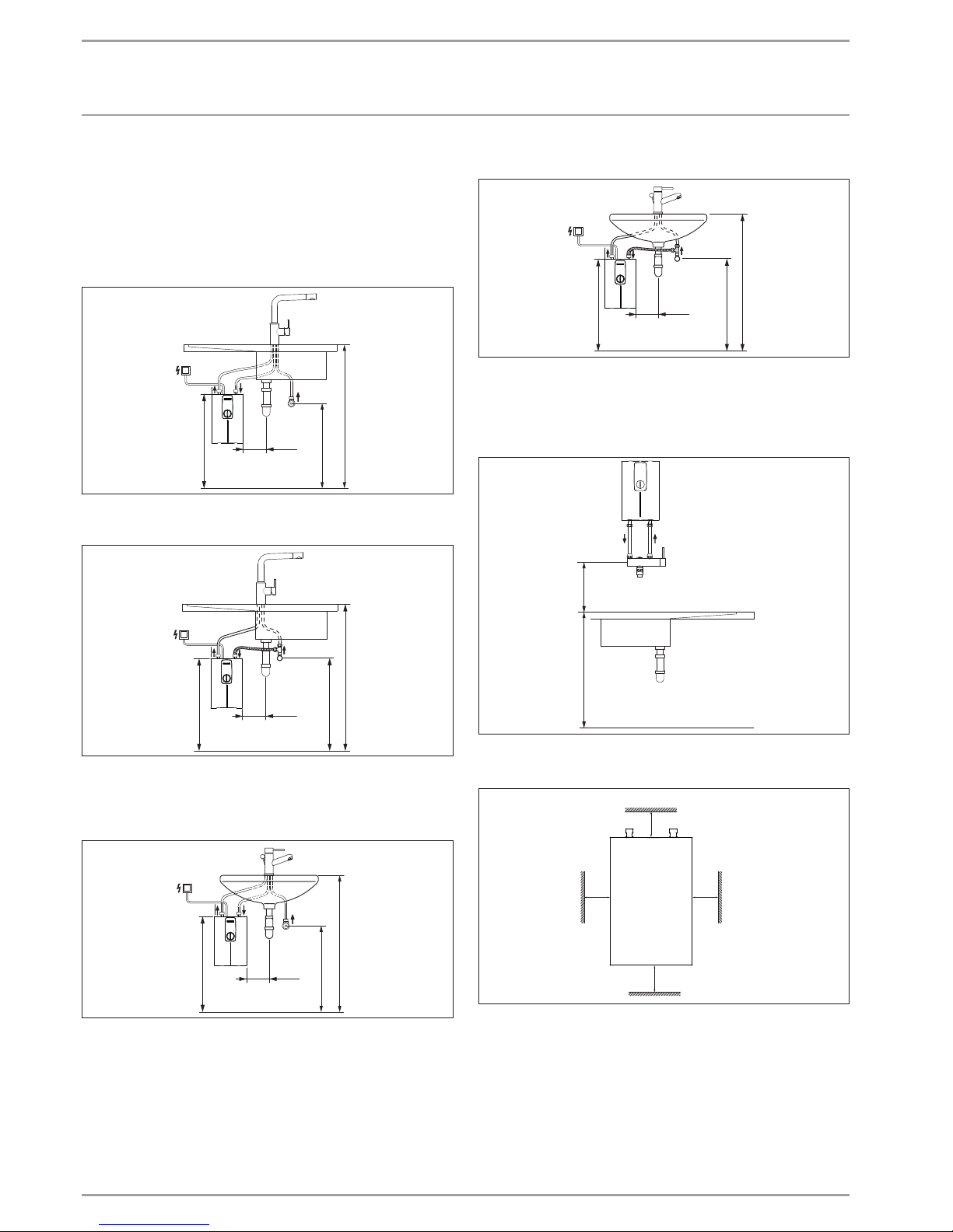
9.1.1 Untertischmontage Spüle DCE11/13 | DCE11/13RC
Drucklos, mit druckloser Armatur
850
550-600
≈ 600
≥ 70
D0000039998
Druckfest, mit druckfester Armatur
850
520 - 570
≈ 600
≥ 70
D0000039997
9.1.2 Untertischmontage Waschtisch DCE11/13 | DCE11/13RC
Drucklos, mit druckloser Armatur
850
520-570
≈ 600
≥ 70
D0000040000
Druckfest, mit druckfester Armatur
850
520 - 570
≈ 600
≥ 70
D0000039999
9.1.3 Übertischmontage Waschtisch DCE11/13H
Drucklos, mit druckloser Armatur
Druckfest, mit druckfester Armatur
850
200-300
D0000050407
9.2 Mindestabstände
≥20≥20
≥50
≥50
D0000060938
Halten Sie die Mindestabstände ein, um einen störungsfreien
Betrieb des Gerätes zu gewährleisten und Wartungsarbeiten
am Gerät zu ermöglichen.
Page 9
DEUTSCH
www.stiebel-eltron.com DCE 11/13| DCE 11/13 RC| DCE 11/13 H | 9
INSTALLATION
Montage
10. Montage
Standardmontage
- Elektroanschluss im oberen Bereich des Gerätes
Weitere Anschlussmöglichkeit siehe Kapitel „Installation/
Montage-Alternativen“.
- Wählbare Anschlussleistung
- Verbrühschutz/ Temperaturbegrenzung
- Elektroanschluss im unteren Bereich des Gerätes
10.1 Standardmontage
Montage des Gerätes
Hinweis
Montieren Sie das Gerät an einer Wand.
Die Wand muss ausreichend tragfähig sein.
D0000039991
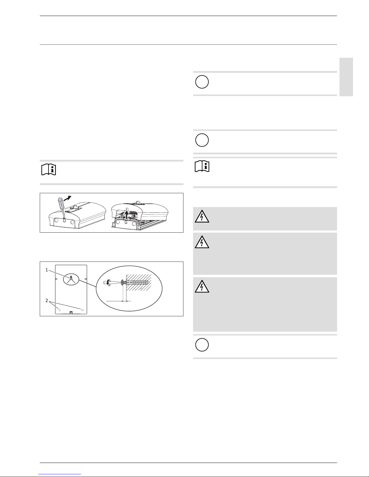
Entriegeln Sie den Schnappverschluss mit einem
Schraubendreher.
Nehmen Sie die Gerätekappe nach vorn ab.
5,5 - 6,5
1
2
D0000039992
1 obere Befestigungsschraube
2 unteren Befestigungsschrauben
Zeichnen Sie die 3 Bohrlöcher mit der beiliegenden Monta-
geschablone (im Mittelteil dieser Anleitung) an.
Bohren Sie die Löcher. Verwenden Sie geeignete Dübel und
Rundkopf- oder Zylinderkopfschrauben mit 8mm Schraubenkopf-Durchmesser. Die Schrauben und Dübel gehören
nicht zum Lieferumfang.
Schrauben Sie die obere Schraube bis auf das angegebene
Maß ein.
Hängen Sie das Gerät auf die Schraube. Ziehen Sie das Gerät
nach unten.
Richten Sie das Gerät horizontal aus. Drehen Sie die unteren
2Schrauben ein.
Wasseranschluss
!
Sachschaden
Das Sieb muss für die Funktion des Gerätes im Kaltwasser
Zulauf des Gerätes eingebaut sein.
Montage der Armatur
Montieren Sie die Armatur. Beachten Sie dabei auch die Be-
dienungs- und Installationsanleitung der Armatur.
!
Sachschaden
Beim Montieren aller Anschlüsse müssen Sie am
Gerät mit passenden Schlüssel gegenhalten.
Hinweis
Nur beim druckfesten Anschluss DCE11/13 | DCE11/13RC:
Montieren Sie den mitgelieferten Anschlussschlauch
3/8 und das T-Stück 3/8.
Elektroanschluss herstellen
WARNUNG Stromschlag
Führen Sie alle elektrischen Anschluss- und Installationsarbeiten nach Vorschrift aus.
WARNUNG Stromschlag
Achten Sie darauf, dass das Gerät an den Schutzleiter
angeschlossen ist.
Das Gerät muss über eine Trennstrecke von mindestens
3mm allpolig vom Netzanschluss getrennt werden können.
WARNUNG Stromschlag
Die Geräte sind im Anlieferungszustand mit einem Anschlusskabel ausgestattet.
Ein Anschluss an eine festverlegte elektrische Leitung ist
möglich, wenn die elektrische Leitung mindestens den
Querschnitt des serienmäßigen Abschlusskabels aufweist. Maximal ist ein Leitungsquerschnitt von 4x6mm²
möglich.
!
Sachschaden
Beachten Sie das Typenschild. Die angegebene Spannung
muss mit der Netzspannung übereinstimmen.
Schließen Sie das Anschlusskabel entsprechend des Elektro-
anschlussplanes an (siehe Kapitel „Installation/Technische
Daten/ Elektroschaltplan“). Die Anschlussleistung ist 2-stufig
wählbar. Die hohe Leistung ist voreingestellt. Wählen Sie
eine andere Leistung siehe Kapitel „Installation/ Montage-Alternativen/ Wählbare Anschlussleistung“.
Page 10
10 |DCE 11/13| DCE 11/13 RC| DCE 11/13 H www.stiebel-eltron.com
INSTALLATION
Inbetriebnahme
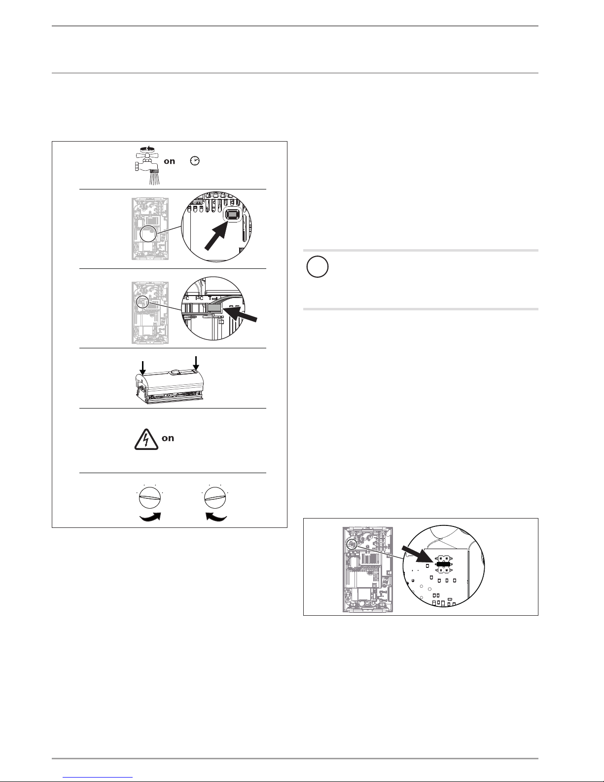
11. Inbetriebnahme
11.1 Erstinbetriebnahme
1.
2.
4.
3.
5.
6.
≥ 60 s
°C
40
50
60
30
20
°C
40
50
60
30
20
DCE 11/13
DCE 11/13 H
DCE 11/13
DCE 11/13 H
D0000039994
Befüllen Sie das Gerät über die Armatur, bis das Leitungs-
netz und das Gerät luftfrei sind. Öffnen Sie mehrfach das
Entnahmeventil.
Aktivieren Sie den elektronischen Sicherheitsschalter (AE3).
Der elektronische Sicherheitsschalter ist bei der Anlieferung
ausgelöst.
Nur beim DCE11/13 | DCE11/13H: Stecken Sie den Stecker
des Temperatureinstellers auf die Elektronik „T-soll“. Beachten Sie die Ausrichtung der Litzen.
Montieren Sie die Gerätekappe, indem Sie die Gerätekappe
aufsetzen und andrücken, bis die beiden Rasthaken hörbar
oben und unten einrasten. Kontrollieren Sie das Einrasten
der Rasthaken.
Schalten Sie die elektrische Netzspannung ein.
Nur beim DCE11/13 | DCE11/13H: Drehen Sie den Tempera-
tur-Einstellknopf zum linken und zum rechten Anschlag.
Führen Sie eine Dichtheitskontrolle durch.
Kreuzen Sie die gewählte Anschlussleistung und die
Nennspannung auf dem Typenschild an. Verwenden Sie dafür
einen Kugelschreiber.
Prüfen Sie die Arbeitsweise des Gerätes.
11.2 Übergabe des Gerätes
Erklären Sie dem Benutzer die Funktion des Gerätes. Machen
Sie ihn mit dem Gebrauch des Gerätes vertraut.
Weisen Sie den Benutzer auf mögliche Gefahren hin, speziell
die Verbrühungsgefahr.
Übergeben Sie diese Anleitung.
11.3 Wiederinbetriebnahme
!
Sachschaden
Nach Unterbrechung der Wasserversorgung müssen Sie
das Gerät mit folgenden Schritten wieder in Betrieb nehmen. Sie vermeiden dadurch die Zerstörung des Blankdraht-Heizsystems.
Schalten Sie das Gerät spannungsfrei, indem Sie die Siche-
rungen ausschalten.
Öffnen Sie die Armatur eine Minute lang, bis das Gerät und
die vorgeschaltete Kaltwasser-Zulaufleitung luftfrei sind.
Schalten Sie die elektrische Netzspannung wieder ein.
Siehe Kapitel „Installation/ Inbetriebnahme“.
12. Außerbetriebnahme
Trennen Sie das Gerät mit der Sicherung in der Hausinstalla-
tion von der Netzspannung.
Entleeren Sie das Gerät (siehe Kapitel „Installation/
Wartung“).
13. Montage-Alternativen
13.1 Wählbare Anschlussleistung
13kW
11kW
D0000039993
Stecken Sie den Codierstecker entsprechend der gewählten
Anschlussleistung auf.
Page 11
DEUTSCH
www.stiebel-eltron.com DCE 11/13| DCE 11/13 RC| DCE 11/13 H | 11
INSTALLATION
Störungsbehebung
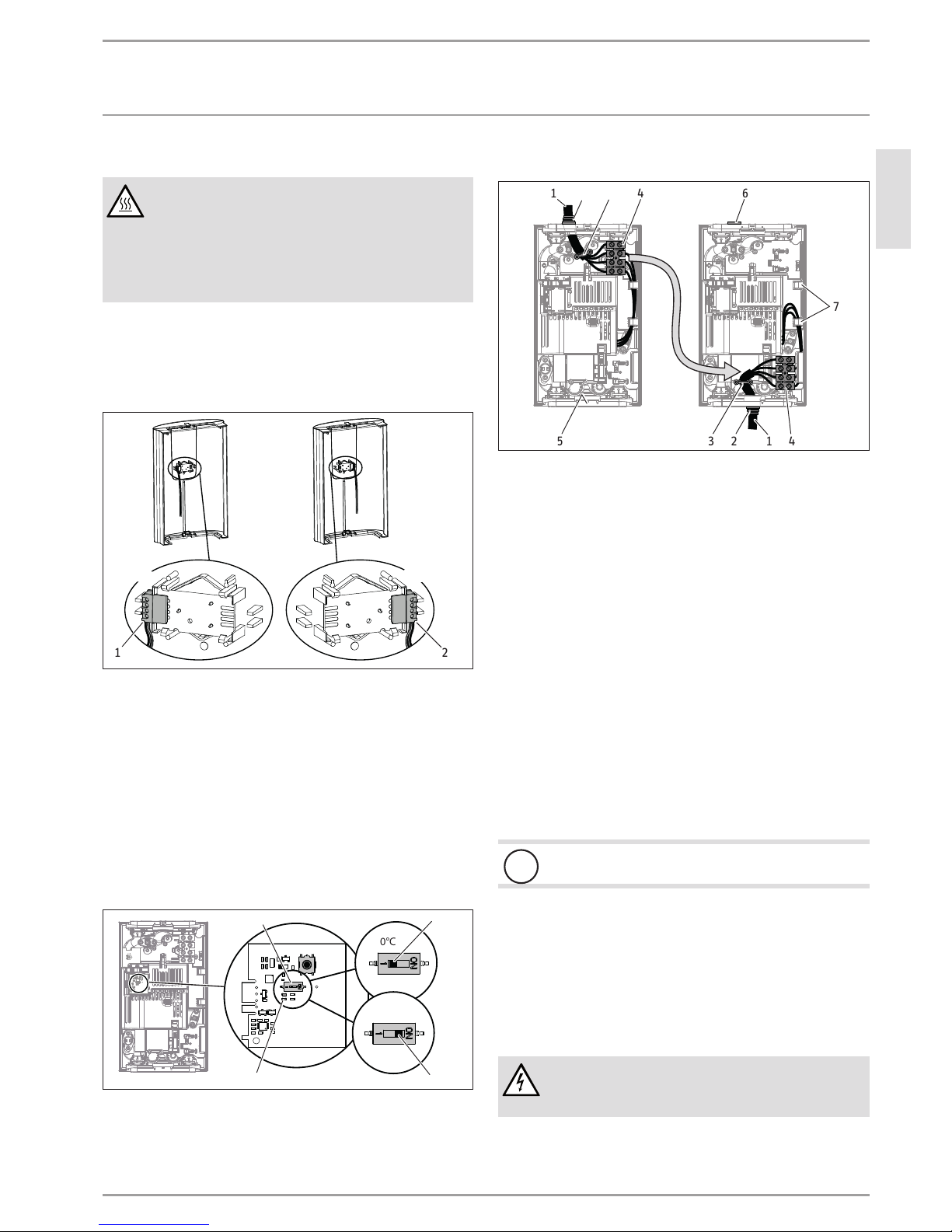
13.2 Verbrühschutz/ Temperaturbegrenzung
WARNUNG Verbrennung
Bei Betrieb mit vorgewärmtem Wasser kann der eingestellte Verbrühschutz unwirksam sein.
In diesem Fall begrenzen Sie die Temperatur an der
vorgeschalteten Zentral-Thermostatarmatur (siehe
Kapitel „Installation/ Gerätebeschreibung/ Zubehör“.
DCE11/13 | DCE11/13H
Die Aktivierung des Verbrühschutzes „max. 43°C“ erfolgt durch
Versetzen des Steckers an der Elektronikplatine in der Gerätekappe.
60 °C
43 °C
D0000039995
1 2
1 ohne Verbrühschutz
2 mit Verbrühschutz 43°C
Nehmen Sie die eingesteckte Elektronikplatine aus der
Bedieneinheit der Gerätekappe. Achten Sie dabei auf die
Schnapphaken.
Versetzen Sie den Stecker in Position „43°C“.
Bauen Sie die Elektronikplatine wieder ein, die Schnapp-
haken müssen einrasten. Achten Sie auf die Knopf- und
Achsposition.
DCE11/13RC
Die Aktivierung des Verbrühschutzes „max. 43°C“ erfolgt durch
Verschieben des DIP-Schalters im Gerät.
60°C
43°C
D0000043533
1
2
4 3
1 DIP-Schalter für Verbrühschutz
2 ohne Verbrühschutz = 60°C
3 mit Verbrühschutz = max. 43°C
4 Grüne LED-Anzeige Dauerlicht bei aktiviertem Verbrühschutz
13.3 Umbau Elektroanschluss unten
D0000043440
21 3 4 6
25 3 41
7
1 Anschlusskabel
2 Kabeltülle
3 Zugentlastung
4 Netzanschlussklemme
5 Markierung für Öffnung vom Anschlusskabel
6 Stopfen
7 Litzenführung
Demontieren Sie die Zugentlastung und das Anschlusskabel
mit der Kabeltülle.
Verschließen Sie die obere Öffnung in der Geräterückwand
mit dem beiliegenden (geschlossenen) Stopfen. Die Schutzart
IP25 (strahlwassergeschützt) ist nur mit dem sachgemäß
montierten Stopfen gewährleistet.
Versetzen Sie die Netzanschlussklemme im Gerät von oben
nach unten. Achten Sie darauf, dass die Netzanschlussklemme einrastet.
Verlegen Sie die Schaltlitzen unter die Litzenführung.
Drücken Sie für das Anschlusskabel eine Öffnung in die Ge-
räterückwand. Drücken Sie mit einem geeigneten Werkzeug
den Kunststoff an der kreisförmigen Markierung von der
Innenseite der Rückwand nach außen heraus. Benutzen Sie
ggf. eine Feile.
!
Sachschaden
Tauschen Sie eine beschädigte Geräterückwand aus.
Montieren Sie das Anschlusskabel mit der Kabeltülle in die
Geräterückwand.
Schließen Sie das Anschlusskabel an die Netzanschluss-
klemme an (siehe Kapitel „Installation/ Technische Daten/
Elektroschaltplan“).
Montieren Sie die Zugentlastung.
14. Störungsbehebung
WARNUNG Stromschlag
Zur Prüfung des Gerätes muss die elektrische Spannung
am Gerät anliegen.
Page 12
12 |DCE 11/13| DCE 11/13 RC| DCE 11/13 H www.stiebel-eltron.com
INSTALLATION
Störungsbehebung
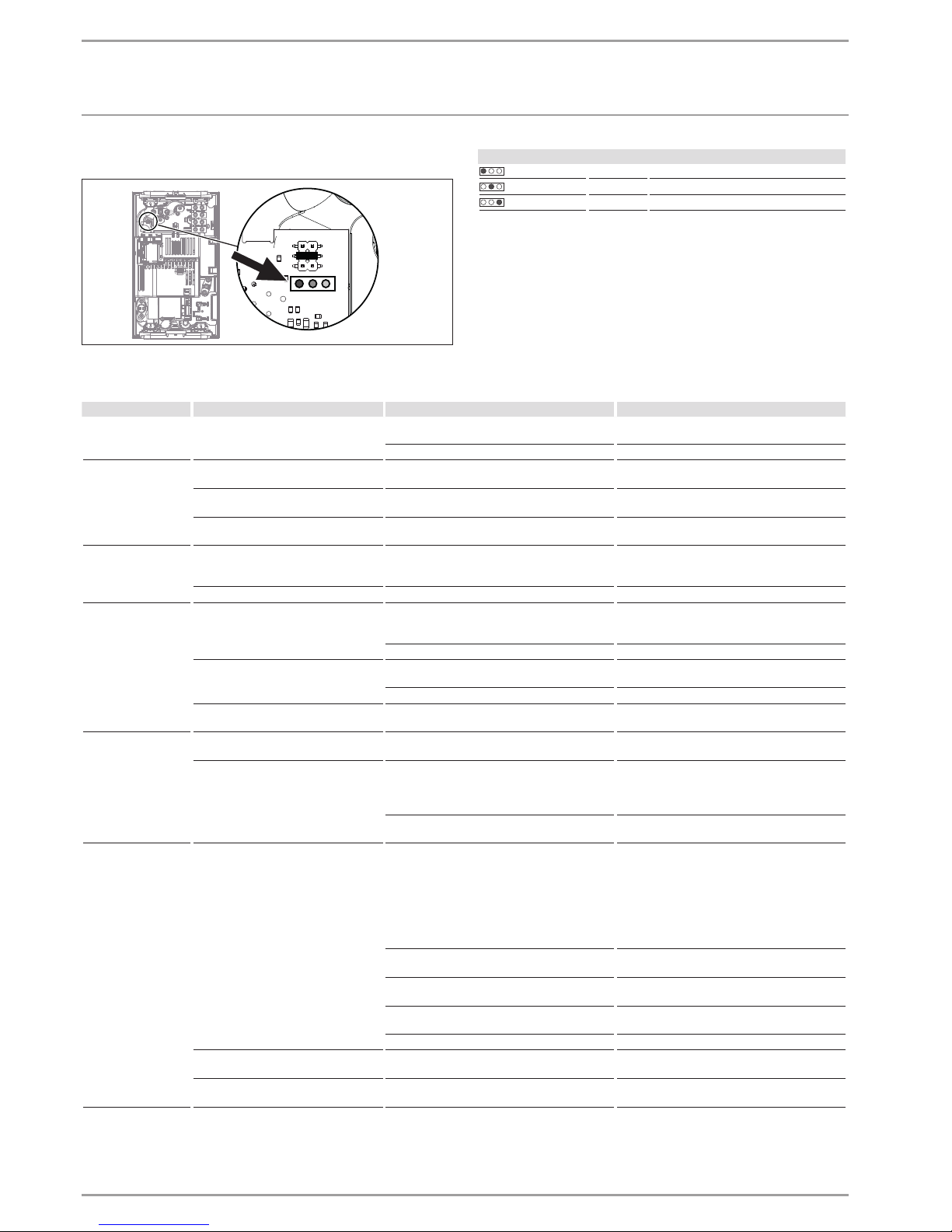
Anzeigemöglichkeiten LED-Diagnoseampel
13kW
11kW
D0000043418
Anzeigemöglichkeiten der Diagnoseampel (LED)
rot leuchtet bei Störung
gelb leuchtet bei Heizbetrieb
grün blinkt: Gerät am Netzanschluss
Störungsbeseitigung
Diagnoseampel Störung Ursache Behebung
keine LED leuchtet Kein warmes Wasser.
Die Sicherung in der Hausinstallation hat ausgelöst.
Prüfen Sie die Sicherung in der Hausinstallation.
Die Elektronik ist defekt. Tauschen Sie das Gerät aus.
grüne LED blinkt
Das Gerät schaltet nicht ein. Der Duschkopf / die Strahlregler sind verkalkt. Entkalken ggf. erneuern Sie den Duschkopf/ die
Strahlregler.
Der Warmwasserdurchfluss ist zu gering.
Das Sieb im Gerät ist verschmutzt. Reinigen Sie das Sieb.
Kein warmes Wasser bei Durchfluss
größer dem Einschaltdurchfluss.
Die Durchflusserkennung DFE ist defekt. Tauschen Sie das Gerät aus.
grüne LED blinkt,
gelbe LED blitzt
Die Solltemperatur wird nicht erreicht. Das Gerät ist an der Leistungsgrenze.
Reduzieren Sie den Durchfluss. Bauen Sie den
Durchflussmengen-Begrenzer ein. Kontrollieren
Sie den Durchflussmengen-Begrenzer.
(nicht in allen Fällen) Die Solltemperatur wird nicht erreicht. Eine Phase fehlt. Prüfen Sie die Sicherung in der Hausinstallation.
grüne LED blinkt,
gelbe LED-Dauerlicht
Die Solltemperatur wird nicht erreicht.
Der Sollwertgeber oder das Verbindungskabel
ist defekt. Das Verbindungskabel ist nicht aufgesteckt.
Stecken Sie das Verbindungskabel auf, ggf. tau-
schen Sie den Sollwertgeber aus.
Der Verbrühschutz ist aktiviert. Deaktivieren Sie den Verbrühschutz.
Kein warmes Wasser bei Durchfluss
größer dem Einschaltdurchfluss.
Das Heizsystem ist defekt. Messen Sie den Widerstand des Heizsystems,
ggf. tauschen Sie das Gerät aus.
Die Elektronik ist defekt. Tauschen Sie das Gerät aus.
Solltemperatur wird nicht erreicht. Der Auslauffühler ist defekt. Prüfen Sie die Verbindung, ggf. tauschen Sie
den Auslauffühler aus.
grüne LED blinkt, rote
LED blitzt
Kein warmes Wasser. Das Gerät ist verkalkt. Tauschen Sie das Gerät aus.
Das Gerät reagiert nicht auf die
Funk-Fernbedienung, „Con“ erscheint
auf dem Display der Funk-Fernbedienung.
Die Funk-Fernbedienung ist nicht angemeldet.
Melden Sie die Funk-Fernbedienung an (siehe
Kapitel „Installation/ Störungsbehebung/
Funk-Fernbedienung anmelden/abmelden“.
Das Verbindungskabel der Funk-Fernbedienung
ist nicht aufgesteckt.
Stecken Sie das Verbindungskabel auf (siehe Ka-
pitel „Installation/ Störungsbeseitigung“).
grüne LED blinkt, rote
LED-Dauerlicht
Kein warmes Wasser.
Der Sicherheitsschalter hat ausgeschaltet.
Beseitigen Sie die Fehlerursache.
Schützen Sie das Heizsystem vor Überhitzung,
indem Sie ein dem Gerät nachgeschaltetes Ent-
nahmeventil eine Minute öffnen. Dadurch wird
das Heizsystem abgekühlt. Aktivieren Sie den
Sicherheitsschalter, indem Sie den Knopf am Si-
cherheitsschalter eindrücken (siehe auch Kapitel
„Installation/ Inbetriebnahme“).
Fehler in der elektronischen Sicherheitseinrichtung.
Tauschen Sie das Gerät aus.
Der Einlaufsensor oder das Verbindungskabel
ist defekt.
Prüfen Sie die Verbindung, ggf. tauschen Sie
den Einlaufsensor aus.
Der Auslaufsensor oder das Verbindungskabel
hat einen Kurzschluss.
Prüfen Sie die Verbindung, ggf. tauschen Sie
den Auslaufsensor aus.
Die Elektronik ist defekt. Tauschen Sie das Gerät aus.
Wunschtemperatur > 55°C wird nicht
erreicht.
Die Kaltwasser-Zulauftemperatur ist höher als
55°C.
Verringern Sie die Kaltwasser-Zulauftemperatur
zum Gerät.
Die Heizung schaltet ab. Die Lufterkennung sensiert Luft im Wasser. Die
Heizleistung schaltet kurzzeitig ab.
Das Gerät geht nach einer Minute wieder in
Betrieb.
Page 13
DEUTSCH
www.stiebel-eltron.com DCE 11/13| DCE 11/13 RC| DCE 11/13 H | 13
INSTALLATION
Wartung
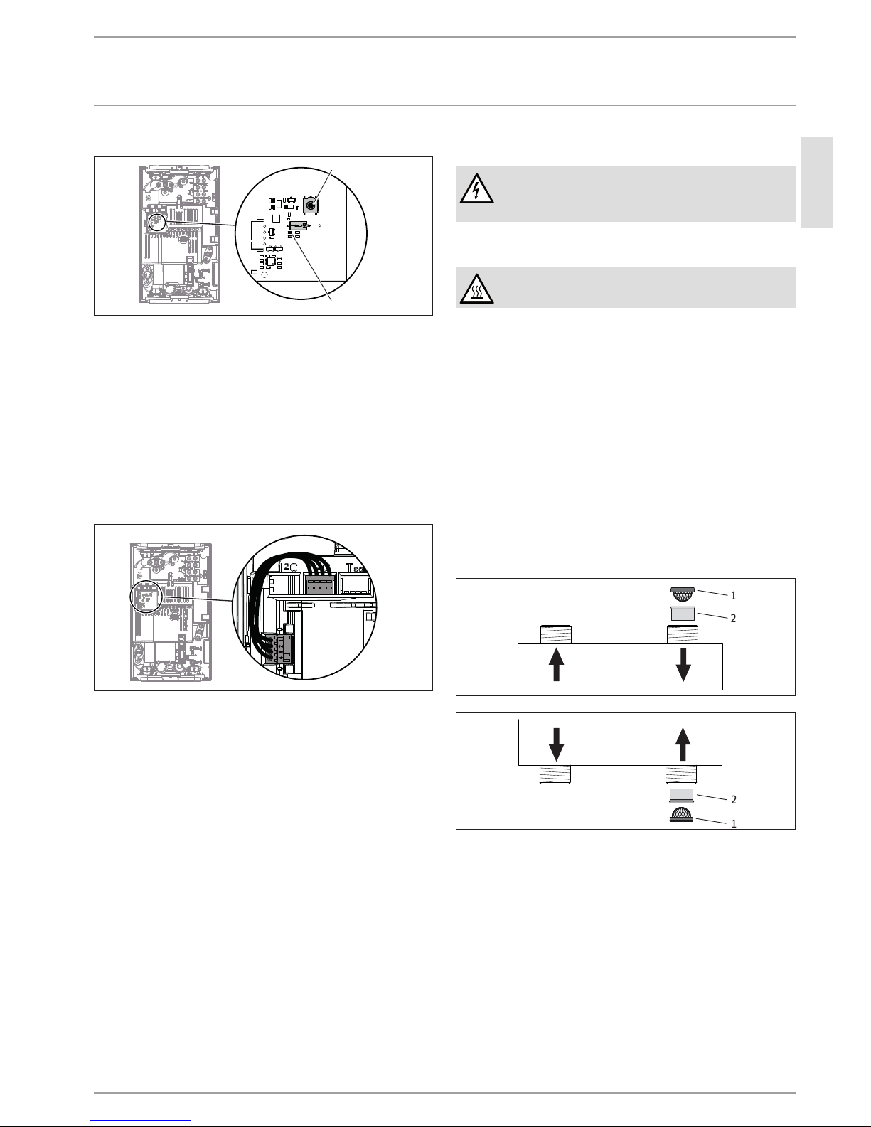
Funk-Fernbedienung vom DCE11/13RC anmelden/abmelden
D0000048647
1
2
1 Taster zum Anmelden und Abmelden
2 Gelbe LED-Anzeige bei aktivierter Funk-Fernbedienung
Zum Starten der Anmeldung der Funk-Fernbedienung
drücken Sie kurz auf den Taster. Die gelbe LED beginnt zu
blinken. Drücken Sie jetzt auf die Taste „1“ der Funk-Fernbedienung. Ein kurzes Blinken der LED signalisiert Ihnen die erfolgreiche Anmeldung. Anschließend erlischt die gelbe LED.
Zur Abmeldung der Funk-Fernbedienung drücken Sie die
Taste 5Sekunden lang. Ein kurzes Blinken der LED signalisiert Ihnen die erfolgreiche Abmeldung. Anschließend erlischt die gelbe LED.
Steckposition der Funk-Fernbedienung vom DCE11/13RC
D0000046810
15. Wartung
WARNUNG Stromschlag
Trennen Sie bei allen Arbeiten das Gerät allpolig vom
Netzanschluss.
Gerät entleeren
WARNUNG Verbrennung
Beim Entleeren kann heißes Wasser austreten.
Für Wartungsarbeiten oder bei Gefahr von Frost entleeren Sie
das Gerät wie folgt:
Schließen Sie das Absperrventil in der Kaltwasser Zuleitung.
Öffnen Sie das Entnahmeventil.
Lösen Sie die Wasseranschlüsse vom Gerät.
Demontieren Sie das Gerät.
Entleeren Sie das Gerät über die Wasseranschlüsse (Rest-
wasser bleibt im Gerät).
Lagerung des Gerätes
Lagern Sie ein demontiertes Gerät frostfrei, da sich Restwas-
ser im Gerät befindet, das Gefrieren und Schäden verursachen kann.
Sieb / Durchflussmengen-Begrenzer reinigen oder ersetzen
D0000040081
1
2
DCE11/13
DCE11/13RC
D0000050374
2
1
DCE11/13H
1 Sieb
2 Durchflussmengen-Begrenzer
Page 14
14 |DCE 11/13| DCE 11/13 RC| DCE 11/13 H www.stiebel-eltron.com
INSTALLATION
Technische Daten
16. Technische Daten
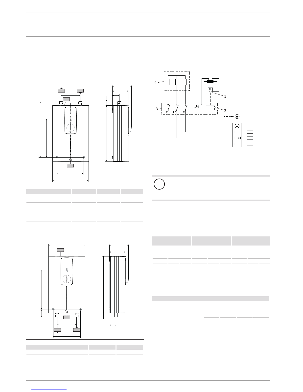
16.1 Maße und Anschlüsse
DCE11/13 | DCE11/13RC
293
188
85
99
35
19
b02
b03
c01
c06
193
291
140
D0000039746
DCE 11/13 DCE 11/13 RC
b02 Durchführung elektr.
Leitungen I
b03 Durchführung elektr.
Leitungen II
c01 Kaltwasser Zulauf Außengewinde G 3/8 A G 3/8 A
c06 Warmwasser Auslauf Außengewinde G 3/8 A G 3/8 A
DCE11/13H
293
85
99
35
19
b02
b03
100
140
c01
c06
193
40
188
D0000050396
DCE 11/13 H
b02 Durchführung elektr. Leitungen I
b03 Durchführung elektr. Leitungen II
c01 Kaltwasser Zulauf Außengewinde G 1/2 A
c06 Warmwasser Auslauf Außengewinde G 1/2 A
16.2 Elektroschaltplan
3/PE ~ 380-415V
D0000040233
3
4
1
2
1 Sicherheitstemperaturbegrenzer
2 elektronischer Sicherheitsschalter
3 Elektronik
4 Heizsystem
!
Sachschaden
Beim Festanschluss schließen Sie das Anschluss-
kabel gemäß der Klemmenbezeichnung der Buchsenklemme an.
16.3 Einsatzbereiche / Umrechnungstabelle
Spezifischer elektrischer Widerstand und spezifische elektrische
Leitfähigkeit (siehe Kapitel „Installation/ Technische Daten/ Datentabelle“).
Normangabe bei
15°C
20°C
25°C
Spez. Widerstand
ρ ≥
Spez. Leitfähigkeit σ ≤
Spez. Widerstand
ρ ≥
Spez. Leitfähigkeit σ ≤
Spez. Widerstand
ρ ≥
Spez. Leitfähigkeit σ ≤
Ωcm mS/m μS/cm Ωcm mS/m μS/cm Ωcm mS/m μS/cm
900 111 1111 800 125 1250 735 136 1361
1100 91 909 970 103 1031 895 112 1117
Auslauftemperatur ca. 60°C für die Küchenspüle und beim Einsatz
einer Thermostatarmatur
Auslaufmenge
Gerät kW 11 13,5
Kaltwasser Zulauftemperatur
6°C l/min 2,9 3,6
10°C l/min 3,2 3,9
14°C l/min 3,4 4,2
Page 15
DEUTSCH
www.stiebel-eltron.com DCE 11/13| DCE 11/13 RC| DCE 11/13 H | 15
INSTALLATION
Technische Daten
Nutztemperatur ca. 38°C für Handwäsche etc.
Mischwassermenge
Gerät kW 11 13,5
Kaltwasser Zulauftemperatur
6°C l/min 5,0 6,1
10°C l/min 5,7 6,9
14°C l/min 6,6 8,1
Tabellenwerte sind auf eine Nennspannung von 400 V bezogen.
Die Mischwassermenge und Auslaufmenge ist abhängig vom vorhandenen Versorgungsdruck und der anliegenden Spannung.
16.4 Druckverluste
Armaturen
Druckverlust bei Durchflussmenge 10l/min
Einhandmischer, ca. MPa 0,04 - 0,08
Thermostatarmatur, ca. MPa 0,03 - 0,05
Handbrause, ca. MPa 0,03 - 0,15
Rohrnetz-Dimensionierungen
Zur Berechnung der Rohrnetz-Dimensionierungen ist für das Gerät
ein Druckverlust von 0,1MPa zu berücksichtigen.
16.5 Störfallbedingungen
Im Störfall können in der Installation kurzfristig Belastungen von
maximal 80 °C bei einem Druck von 1,0 MPa auftreten.
16.6 Landesspezifische Zulassungen und Zeugnisse
Prüfzeichen sind auf dem Typenschild ersichtlich.
16.7 Angaben zum Energieverbrauch
Die Produktdaten entsprechen den EU-Verordnungen zur Richtlinie für umweltgerechte Gestaltung energieverbrauchsrelevanter
Produkte (ErP).
DCE 11/13 DCE 11/13 RC DCE 11/13 H
230770 230771 232792
Hersteller STIEBEL ELTRON STIEBEL ELTRON STIEBEL ELTRON
Lastprofil XS XS XS
Energieeffizienzklasse A A A
Jährlicher Stromverbrauch kWh 465 465 465
Energetischer Wirkungsgrad % 40 40 40
Temperatureinstellung ab Werk °C 60 60 60
Schallleistungspegel dB(A) 15 15 15
Besondere Hinweise zur Effizienzmessung Angaben bei Pmax. Angaben bei Pmax. Angaben bei Pmax.
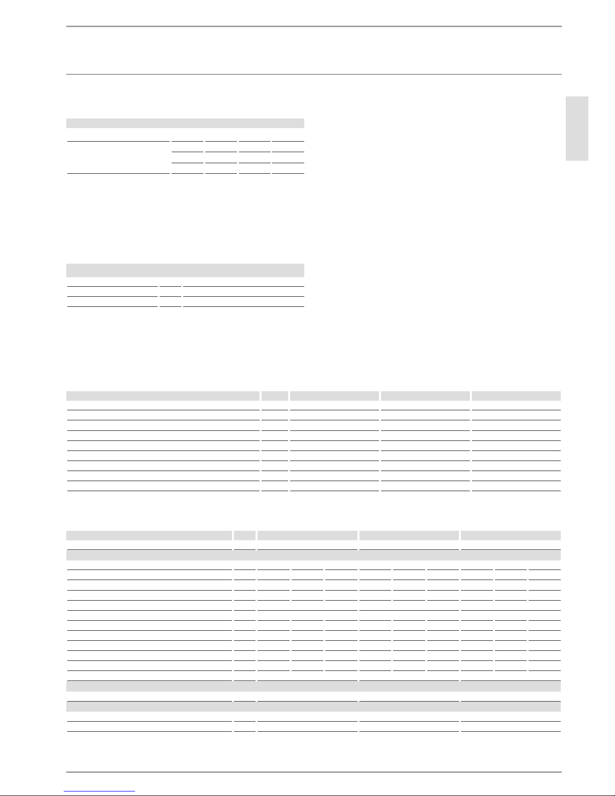
16.8 Datentabelle
DCE 11/13 DCE 11/13 compact RC DCE 11/13 H
230770 230771 232792
Elektrische Daten
Nennspannung V 380 400 415 380 400 415 380 400 415
Nennleistung kW 10/12,1 11/13,5 11,8/14,5 10/12,1 11/13,5 16,8/20,2 10/12,1 11/13,5 11,8/14,5
Nennstrom A 15,4/18,5 16,2/19,5 16,8/20,2 15,4/18,5 16,2/19,5 16,4/20,1 15,4/18,5 16,2/19,5 16,8/20,2
Absicherung A 16/20 16/20 16/20 16/20 16/20 16/20 16/20 16/20 16/20
Phasen 3/PE 3/PE 3/PE
Frequenz Hz 50/60 50/60 50/- 50/60 50/60 50/- 50/60 50/60 50/Spezifischer Widerstand ρ
15
≥ (bei ϑkalt ≤25°C) Ω cm 900 900 900 900 900 900 900 900 900
Spezifische Leitfähigkeit σ15 ≤ (bei ϑkalt ≤25°C) μS/cm 1111 1111 1111 1111 1111 1111 1111 1111 1111
Spezifischer Widerstand ρ
15
≥ (bei ϑkalt ≤55°C) Ω cm 1100 1100 1100 1100 1100 1100 1100 1100 1100
Spezifische Leitfähigkeit σ
15
≤ (bei ϑkalt ≤55°C) μS/cm 909 909 909 909 909 909 909 909 909
Max. Netzimpedanz bei 50Hz Ω 0,28 0,26 0,24 0,28 0,26 0,24 0,28 0,26 0,24
Elektronik Stand by W < 2 < 2 < 2
Anschlüsse
Wasseranschluss G 3/8 A G 3/8 A G 1/2 A
Einsatzgrenzen
Max. zulässiger Druck MPa 1 1 1
Max. Zulauftemperatur für Nacherwärmung °C 55 55 55
Page 16
16 |DCE 11/13| DCE 11/13 RC| DCE 11/13 H www.stiebel-eltron.com
INSTALLATION
Technische Daten
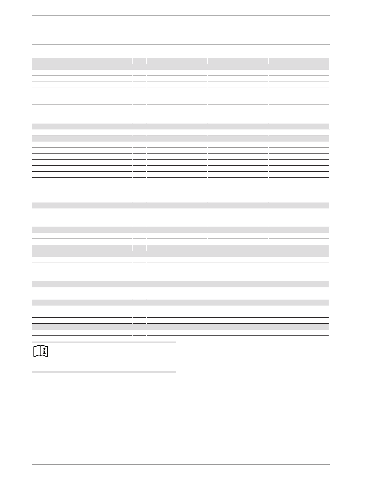
DCE 11/13 DCE 11/13 compact RC DCE 11/13 H
Werte
Max. zulässige Zulauftemperatur °C 70 70 70
Ein l/min >2,5 >2,5 >2,5
Volumenstrom für Druckverlust l/min 4 4 4
Druckverlust bei Volumenstrom MPa 0,06 0,06 0,07
Druckverlust bei Volumenstrom ohne Durchflussmen-
gen-Begrenzer
MPa 0,015 0,015 0,025
Volumenstrom-Begrenzung bei l/min 4 4 4
Warmwasserdarbietung l/min 3,7/4,5 3,7/4,5 3,7/4,5
Δϑ bei Darbietung K 43 43 43
Hydraulische Daten
Nenninhalt l 0,2 0,2 0,2
Ausführungen
Montageart Untertisch X X
Montageart Übertisch X
Anschlussleistung wählbar X X X
Temperatureinstellung °C 20-60 20-60 20-60
Schutzklasse 1 1 1
Isolierblock Kunststoff Kunststoff Kunststoff
Heizsystem Wärmeerzeuger Blankdraht Blankdraht Blankdraht
Kappe und Rückwand Kunststoff Kunststoff Kunststoff
Schutzart (IP) IP24 IP24 IP24
Farbe weiß weiß weiß
Dimensionen
Höhe mm 293 293 293
Breite mm 188 188 188
Tiefe mm 99 85 99
Gewichte
Gewicht kg 2,5 2,5 2,5
Mini-FFB
Einsatzgrenzen
Temperatureinstellbereich °C 20-60
Funkfrequenz EU MHz 868,3
Frequenzband MHz 863,000 - 863,600
Funkreichweite Gebäude ca. m 25
Ausführungen
Schutzart (IP) IPX7
Batterietyp CR2032-3V
Dimensionen
Höhe mm 132
Breite mm 65
Tiefe mm 18,5
Gewichte
Gewicht kg 0,12
Hinweis
Die Funkreichweite ist abhängig von den baulichen Gegebenheiten. Eine Funktion durch eine Geschossdecke
kann nicht immer garantiert werden.
Page 17

DEUTSCH
www.stiebel-eltron.com DCE 11/13| DCE 11/13 RC| DCE 11/13 H | 17
KUNDENDIENST UND GARANTIE
Erreichbarkeit
Sollte einmal eine Störung an einem unserer Produkte auftreten, stehen wir Ihnen natürlich mit Rat und Tat zur Seite.
Rufen Sie uns an:
05531 702-111
oder schreiben Sie uns:
Stiebel Eltron GmbH & Co. KG
- Kundendienst Fürstenberger Straße 77, 37603 Holzminden
E-Mail: kundendienst@stiebel-eltron.de
Fax: 05531 702-95890
Weitere Anschriften sind auf der letzten Seite aufgeführt.
Unseren Kundendienst erreichen Sie telefonisch rund um die
Uhr, auch an Samstagen und Sonntagen sowie an Feiertagen.
Kundendiensteinsätze erfolgen während unserer Geschäftszeiten (von 7.15 bis 18.00 Uhr, freitags bis 17.00 Uhr). Als Sonderservice bieten wir Kundendiensteinsätze bis 21.30 Uhr. Für diesen Sonderservice sowie Kundendiensteinsätze an Wochenenden und Feiertagen werden höhere Preise berechnet.
Garantiebedingungen
Diese Garantiebedingungen regeln zusätzliche Garantieleistungen von uns gegenüber dem Endkunden. Sie treten neben die
gesetzlichen Gewährleistungsansprüche des Kunden. Die gesetzlichen Gewährleistungsansprüche gegenüber den sonstigen Vertragspartnern sind nicht berührt.
Diese Garantiebedingungen gelten nur für solche Geräte, die
vom Endkunden in der Bundesrepublik Deutschland als Neugeräte erworben werden. Ein Garantievertrag kommt nicht zustande, soweit der Endkunde ein gebrauchtes Gerät oder ein
neues Gerät seinerseits von einem anderen Endkunden erwirbt.
Inhalt und Umfang der Garantie
Die Garantieleistung wird erbracht, wenn an unseren Geräten
ein Herstellungs- und/oder Materialfehler innerhalb der Garantiedauer auftritt. Die Garantie umfasst jedoch keine Leistungen
für solche Geräte, an denen Fehler, Schäden oder Mängel aufgrund von Verkalkung, chemischer oder elektrochemischer
Einwirkung, fehlerhafter Aufstellung bzw. Installation sowie
unsachgemäßer Einregulierung, Bedienung oder unsachgemäßer Inanspruchnahme bzw. Verwendung auftreten. Ebenso
ausgeschlossen sind Leistungen aufgrund mangelhafter oder
unterlassener Wartung, Witterungseinflüssen oder sonstigen
Naturerscheinungen.
Die Garantie erlischt, wenn am Gerät Reparaturen, Eingriffe oder
Abänderungen durch nicht von uns autorisierte Personen vorgenommen wurden.
Die Garantieleistung umfasst die sorgfältige Prüfung des Gerätes, wobei zunächst ermittelt wird, ob ein Garantieanspruch
besteht. Im Garantiefall entscheiden allein wir, auf welche Art
der Fehler behoben wird. Es steht uns frei, eine Reparatur des
Gerätes ausführen zu lassen oder selbst auszuführen. Etwaige
ausgewechselte Teile werden unser Eigentum.
Für die Dauer und Reichweite der Garantie übernehmen wir
sämtliche Material- und Montagekosten.
Soweit der Kunde wegen des Garantiefalles aufgrund gesetzlicher Gewährleistungsansprüche gegen andere Vertragspartner
Leistungen erhalten hat, entfällt eine Leistungspflicht von uns.
Soweit eine Garantieleistung erbracht wird, übernehmen wir
keine Haftung für die Beschädigung eines Gerätes durch Diebstahl, Feuer, Aufruhr oder ähnliche Ursachen.
Über die vorstehend zugesagten Garantieleistungen hinausgehend kann der Endkunde nach dieser Garantie keine Ansprüche
wegen mittelbarer Schäden oder Folgeschäden, die durch das
Gerät verursacht werden, insbesondere auf Ersatz außerhalb des
Gerätes entstandener Schäden, geltend machen. Gesetzliche
Ansprüche des Kunden uns gegenüber oder gegenüber Dritten
bleiben unberührt.
Garantiedauer
Für im privaten Haushalt eingesetzte Geräte beträgt die Garantiedauer 24 Monate; im Übrigen (zum Beispiel bei einem Einsatz
der Geräte in Gewerbe-, Handwerks- oder Industriebetrieben)
beträgt die Garantiedauer 12 Monate.
Die Garantiedauer beginnt für jedes Gerät mit der Übergabe des
Gerätes an den Kunden, der das Gerät zum ersten Mal einsetzt.
Garantieleistungen führen nicht zu einer Verlängerung der
Garantiedauer. Durch die erbrachte Garantieleistung wird keine
neue Garantiedauer in Gang gesetzt. Dies gilt für alle erbrachten
Garantieleistungen, insbesondere für etwaig eingebaute Ersatzteile oder für die Ersatzlieferung eines neuen Gerätes.
Inanspruchnahme der Garantie
Garantieansprüche sind vor Ablauf der Garantiedauer, innerhalb
von zwei Wochen, nachdem der Mangel erkannt wurde, bei uns
anzumelden. Dabei müssen Angaben zum Fehler, zum Gerät
und zum Zeitpunkt der Feststellung gemacht werden. Als Garantienachweis ist die Rechnung oder ein sonstiger datierter
Kaufnachweis beizufügen. Fehlen die vorgenannten Angaben
oder Unterlagen, besteht kein Garantieanspruch.
Garantie für in Deutschland erworbene, jedoch außerhalb Deutschlands eingesetzte Geräte
Wir sind nicht verpflichtet, Garantieleistungen außerhalb der
Bundesrepublik Deutschland zu erbringen. Bei Störungen eines
im Ausland eingesetzten Gerätes ist dieses gegebenenfalls auf
Gefahr und Kosten des Kunden an den Kundendienst in
Deutschland zu senden. Die Rücksendung erfolgt ebenfalls auf
Gefahr und Kosten des Kunden. Etwaige gesetzliche Ansprüche
des Kunden uns gegenüber oder gegenüber Dritten bleiben
auch in diesem Fall unberührt.
Außerhalb Deutschlands erworbene Geräte
Für außerhalb Deutschlands erworbene Geräte gilt diese Garantie nicht. Es gelten die jeweiligen gesetzlichen Vorschriften und
gegebenenfalls die Lieferbedingungen der Ländergesellschaft
bzw. des Importeurs.
Page 18

18 |DCE 11/13| DCE 11/13 RC| DCE 11/13 H www.stiebel-eltron.com
UMWELT UND RECYCLING
Entsorgung von Transport- und
Verkaufsverpackungsmaterial
Damit Ihr Gerät unbeschädigt bei Ihnen ankommt, haben wir
es sorgfältig verpackt. Bitte helfen Sie, die Umwelt zu schützen,
und entsorgen Sie das Verpackungsmaterial des Gerätes sachgerecht. Wir beteiligen uns gemeinsam mit dem Großhandel
und dem Fachhandwerk/ Fachhandel in Deutschland an einem
wirksamen Rücknahme- und Entsorgungskonzept für die umweltschonende Aufarbeitung der Verpackungen.
Überlassen Sie die Transportverpackung dem Fachhandwerker
beziehungsweise dem Fachhandel.
Entsorgen Sie Verkaufsverpackungen über eines der Dualen
Systeme in Deutschland.
Entsorgung von Altgeräten in Deutschland
Geräteentsorgung
Die mit diesem Symbol gekennzeichneten Geräte dürfen nicht mit dem Hausmüll entsorgt werden.
Als Hersteller sorgen wir im Rahmen der Produktverantwortung für eine umweltgerechte Behandlung und Verwertung
der Altgeräte. Weitere Informationen zur Sammlung und Entsorgung erhalten Sie über Ihre Kommune oder Ihren Fachhandwerker/ Fachhändler.
Bereits bei der Entwicklung neuer Geräte achten wir auf eine
hohe Recyclingfähigkeit der Materialien.
Über das Rücknahmesystem werden hohe Recyclingquoten
der Materialien erreicht, um Deponien und die Umwelt zu entlasten. Damit leisten wir gemeinsam einen wichtigen Beitrag
zum Umweltschutz.
Entsorgung außerhalb Deutschlands
Entsorgen Sie dieses Gerät fach- und sachgerecht nach den
örtlich geltenden Vorschriften und Gesetzen.
Page 19

DEUTSCH
www.stiebel-eltron.com DCE 11/13| DCE 11/13 RC| DCE 11/13 H | 19
NOTIZEN
Page 20

20 |DCE 11/13| DCE 11/13 RC| DCE 11/13 H www.stiebel-eltron.com
CONTENTS | SPECIAL INFORMATION
SPECIAL INFORMATION
OPERATION
1. General information ��������������������������������������� 21
1.1 Safety instructions ���������������������������������������������� 21
1.2 Other symbols in this documentation ���������������������� 21
1.3 Units of measurement ����������������������������������������� 21
2. Safety �������������������������������������������������������� 21
2.1 Intended use ����������������������������������������������������� 21
2.2 General safety instructions �����������������������������������21
2.3 Test symbols ����������������������������������������������������� 22
3. Appliance description ������������������������������������� 22
4. Settings ����������������������������������������������������� 22
4.1 DCE11/13 | DCE11/13H ������������������������������������� 22
4.2 DCE 11/13 RC ����������������������������������������������������22
4.3 Anti-scalding protection/ temperature limit ������������� 23
4.4 Following an interruption of the water supply ����������� 23
5. Cleaning, care and maintenance ������������������������� 23
6. Troubleshooting �������������������������������������������� 23
INSTALLATION
7. Safety �������������������������������������������������������� 24
7.1 General safety instructions ����������������������������������� 24
7.2 Instructions, standards and regulations ������������������� 24
8. Appliance description ������������������������������������� 24
8.1 Standard delivery ����������������������������������������������� 24
8.2 Accessories ������������������������������������������������������� 24
9. Preparations ������������������������������������������������ 24
9.1 Installation site �������������������������������������������������� 24
9.2 Minimum clearances ������������������������������������������� 25
10. Installation �������������������������������������������������� 26
10.1 Standard installation ������������������������������������������� 26
11. Commissioning ��������������������������������������������� 27
11.1 Initial start-up ��������������������������������������������������� 27
11.2 Appliance handover �������������������������������������������� 27
11.3 Recommissioning ����������������������������������������������� 27
12. Shutdown ��������������������������������������������������� 27
13. Installation options ���������������������������������������� 27
13.1 Adjustable connected load������������������������������������ 27
13.2 Anti-scalding protection/ temperature limit ������������� 28
13.3 Conversion for power connection from below ������������ 28
14. Troubleshooting �������������������������������������������� 28
15. Maintenance ������������������������������������������������ 30
16. Specification ������������������������������������������������ 31
16.1 Dimensions and connections ��������������������������������� 31
16.2 Wiring diagram ������������������������������������������������� 31
16.3 Application areas / conversion table ����������������������� 31
16.4 Pressure drop ��������������������������������������������������� 32
16.5 Fault conditions ������������������������������������������������� 32
16.6 Country-specific approvals and certifications ������������� 32
16.7 Details on energy consumption ������������������������������ 32
16.8 Data table �������������������������������������������������������� 33
SPECIAL INFORMATION
- The appliance may be used by children aged 3
and older and persons with reduced physical,
sensory or mental capabilities or a lack of experience and know-how, provided that they are
supervised or they have been instructed on how
to use the appliance safely and have understood
the resulting risks. Children must never play with
the appliance. Children must never clean the appliance or perform user maintenance unless they
are supervised.
- During operation, the tap can reach temperatures
in excess of 60 °C. There is a risk of scalding at
outlet temperatures in excess of 43°C.
- Ensure the appliance can be separated from the
power supply by an isolator that disconnects all
poles with at least 3 mm contact separation.
- The power cable may only be replaced (for example if damaged) by a qualified contractor authorised by the manufacturer, using an original spare
part.
- Secure the appliance as described in chapter "Installation/ Installation".
- Observe the maximum permissible pressure (see
chapter "Installation/ Specification/ Data table").
- Drain the appliance as described in chapter "Installation/ Maintenance/ Draining the appliance".
GUARANTEE
ENVIRONMENT AND RECYCLING
INSTALLATION TEMPLATE (IN THE MIDDLE OF THESE INSTRUCTIONS)
Page 21

OPERATION
General information
ENGLISH
www.stiebel-eltron.com DCE 11/13| DCE 11/13 RC| DCE 11/13 H | 21
OPERATION
1. General information
The chapter "Operation" is intended for appliance users and qualified contractors.
The chapter "Installation" is intended for qualified contractors.
Note
Read these instructions carefully before using the appliance and retain them for future reference.
Pass on the instructions to a new user if required.
1.1 Safety instructions
1.1.1 Structure of safety instructions
KEYWORD Type of risk
Here, possible consequences are listed that may result
from failure to observe the safety instructions.
Steps to prevent the risk are listed.
1.1.2 Symbols, type of risk
Symbol Type of risk
Injury
Electrocution
Burns
(burns, scalding)
1.1.3 Keywords
KEYWORD Meaning
DANGER Failure to observe this information will result in serious
injury or death.
WARNING Failure to observe this information may result in serious
injury or death.
CAUTION Failure to observe this information may result in non-seri-
ous or minor injury.
1.2 Other symbols in this documentation
Note
Notes are bordered by horizontal lines above and below
the text. General information is identified by the adjacent
symbol.
Read these texts carefully.
Symbol
Material losses
(appliance damage, consequential losses and environmental pollution)
Appliance disposal
This symbol indicates that you have to do something. The ac-
tion you need to take is described step by step.
1.3 Units of measurement
Note
Unless specified otherwise, all dimensions are given in
mm.
2. Safety
2.1 Intended use
This appliance is intended for domestic use. It can be used safely
by untrained persons. The appliance can also be used in a non-domestic environment, e.g. in a small business, as long as it is used
in the same way.
This appliance is suitable for heating domestic hot water or for
reheating preheated water. The appliance is designed for one
kitchen sink or one washbasin.
Any other use beyond that described shall be deemed inappropriate. Observation of these instructions and of instructions for any
accessories used is also part of the correct use of this appliance.
2.2 General safety instructions
WARNING Burns
During operation, the tap can reach temperatures in excess of 60 °C.
There is a risk of scalding at outlet temperatures in excess of 43°C.
!
WARNING Injury
The appliance may be used by children aged 3 and older
and persons with reduced physical, sensory or mental
capabilities or a lack of experience and know-how, provided that they are supervised or they have been instructed on how to use the appliance safely and have
understood the resulting risks. Children must never play
with the appliance. Children must never clean the appliance or perform user maintenance unless they are
supervised.
WARNING Electrocution
A damaged power cable may only be replaced by a qualified contractor. This is to avoid putting yourself at risk.
!
Material losses
Protect the appliance and tap against frost.
!
!
Page 22

OPERATION
Appliance description
22 |DCE 11/13| DCE 11/13 RC| DCE 11/13 H www.stiebel-eltron.com
2.3 Test symbols
See type plate on the appliance.
3. Appliance description
The electronically controlled compact instantaneous water heater
maintains a constant outlet temperature up to its output limit,
irrespective of the inlet temperature.
The appliance warms the water directly at the draw-off point, as
soon as you turn on the hot water tap. The short pipe runs ensure
that energy and water losses are minimal.
For the start flow rate, see "Installation/ Specification/ Data
table".
The DHW output depends on the cold water temperature, the
heating output, the flow rate and the set temperature required.
DHW temperature
The DHW outlet temperature can be variably adjusted.
Heating system
The bare wire heating system is suitable for hard and soft water
areas. This heating system has a low susceptibility to scale buildup. The heating system ensures quick and efficient DHW provision.
Note
The appliance is equipped with an air detector that largely prevents damage to the heating system. If, during operation, air is drawn into the appliance, the heater shuts
down automatically for one minute, thereby protecting
the heating system.
4. Settings
4.1 DCE11/13 | DCE11/13H
Operation
°C
40
50
60
30
20
D0000039989
1
1 Temperature selector: Temperature setting range
20°C– 60°C
4.2 DCE 11/13 RC
With the wireless remote control, the temperature setting can
be adjusted by wireless control. The selected temperature is displayed on the remote control.
The wireless remote control provided is registered to the receiver
module. Only a registered remote control can alter the settings
on the appliance.
The wireless range is reduced by obstacles between the appliance
and the remote control.
You can mount the wireless remote control anywhere using the
wall mounting bracket supplied in the standard delivery.
Operation
1
+
-
2
D0000039990
2
1
3
1 Display
2 Temperature selection 20°C – 60°C in 0.5°C steps, using the
+ and - buttons
3 Memory keys 1 and 2
The wireless remote control is normally in power save mode,
which means the display is switched off. Pressing any key activates
the wireless remote control, the temperature display appears. The
progress bar indicates that data is being transmitted to the device.
If no key is pressed within 10seconds the wireless remote control
automatically switches back to power save mode.
The selected temperature is also maintained in power save mode.
Saving temperature to memory keys
Select the required temperature.
Press memory key 1 or 2 for 2seconds. The temperature dis-
play flashes once to confirm.
The heater of the appliance can be switched off (display
message OFF). To switch the heater off, select the minimum
temperature (20°C), then press the "-" button once.
Battery change
1
+
-
2
D0000047484
1
1 Battery change symbol
When the battery symbol illuminates, change the battery of the
wireless remote control. A change of battery may also become
Page 23

OPERATION
Cleaning, care and maintenance
ENGLISH
www.stiebel-eltron.com DCE 11/13| DCE 11/13 RC| DCE 11/13 H | 23
necessary when the temperature settings are not received by the
device and/or the transmission range decreases.
!
Material losses
Remove the old battery.
Any damage caused by a leaking battery is excluded from
the warranty.
Open the casing of the wireless remote control by unscrew-
ing the 4 screws on the underside of the device.
Replace with a CR2032-type battery. Never use rechargeable
NiCd batteries. Ensure correct polarity of the new battery (+
at the top).
Put the casing back together and re-insert the 4 screws.
When reassembling the casing, do not damage the sealing
gasket.
The stored values for keys 1 and 2 are retained during the battery
change.
Battery disposal
Never dispose of batteries with domestic waste. Spent
batteries contain hazardous substances that are detrimental to the environment and human health. Dispose
of batteries through your dealer or via a central recycling
point for special waste.
4.3 Anti-scalding protection/ temperature limit
When activating the anti-scalding protection the DHW temperature
can only be set to between 20°C and 43°C.
Higher temperature settings are not implemented.
Use the anti-scalding protection in locations such as child nurs-
eries, hospitals, care homes etc.
Note
The qualified contractor can activate the anti-scalding
protection in your appliance (see chapter "Installation/
Installation options/ Anti-scalding protection/ Temperature limiter").
4.4 Following an interruption of the water supply
See chapter "Installation/ Commissioning/ Restarting".
5. Cleaning, care and maintenance
Never use abrasive or corrosive cleaning agents. A damp
cloth is sufficient for cleaning the appliance.
Check the taps regularly. Limescale deposits at the tap out-
lets can be removed using commercially available descaling
agents.
Have the electrical safety of the appliance regularly checked
by an electrician.
6. Troubleshooting
Problem Cause Remedy
The appliance will not
start despite the DHW
valve being fully open.
No power at the appliance.
Check the fuse/MCB in
your fuse box/distribution panel.
The flow rate is too low.
The aerator in the tap is
scaled up or dirty.
Clean and/or descale the
aerator or replace the
special aerator.
The water supply has
been interrupted.
Vent the appliance and
the cold water inlet line
(see chapter "Installation/ Commissioning/
Restarting").
The required temperature is not being reached.
Internal anti-scalding
protection is activated.
Ask a qualified contractor to deactivate the anti-scalding protection.
The appliance is no
longer heating the water,
the cold water inlet temperature >55°C.
Reduce the cold water
inlet temperature.
“Con” occasionally appears on the display.
The wireless remote control is outside its range.
Reduce the distance
between the wireless
remote control and the
appliance. Resend the
temperature request.
“Con” frequently appears
on the display.
The battery is at the end
of its capacity.
Change the battery (see
chapter "Operation/
Appliance description/
Battery change").
If you cannot remedy the fault, notify your contractor. To facilitate
and speed up your request, provide the number from the type
plate (000000-0000-000000).
Nr.: 000000-0000-000000
D0000040351
Page 24

24 |DCE 11/13| DCE 11/13 RC| DCE 11/13 H www.stiebel-eltron.com
INSTALLATION
Safety
INSTALLATION
7. Safety
Only a qualified contractor should carry out installation, commissioning, maintenance and repair of the appliance.
7.1 General safety instructions
We guarantee the trouble-free function and operational reliability only if original accessories and spare parts intended for the
appliance are used.
!
Material losses
Observe the maximum permissible inlet temperature (see
chapter "Installation/ Specification/ Data table"). Higher
temperatures may damage the appliance. You can limit
the inlet temperature by means of a central thermostatic
valve (see chapter "Installation/ Appliance description/
Accessories").
7.2 Instructions, standards and regulations
Note
Observe all applicable national and regional regulations
and instructions.
The specific electrical resistance of the water must not fall below
that stated on the type plate. In a linked water network, factor in
the lowest electrical resistance of the water (see chapter "Installation/ Specification/ Data table"). Your water supply utility will advise you of the specific electrical water resistance or conductivity.
8. Appliance description
8.1 Standard delivery
The following are delivered with the appliance:
- Plug for cable entry
- Installation template in the centre part of these instructions
- Connection hose 3/8, 500mm long, with gaskets*
- Tee 3/8*
* for connection as pressure-tested appliances DCE11/13 and
DCE11/13RC
8.2 Accessories
Load shedding relay
Priority control can be set up using an electronic load-shedding
relay, in order to separate a second instantaneous water heater
from the mains power supply for example.
The responding current on the load shedding relay must be ≤2A.
It is connected to the central L terminal.
Non-pressurised taps
- WEN sensor tap for washbasins
- MEK mono lever mixer tap
- WKM twin-lever mixer tap
Pressure-tested tap
- WEH sensor tap for washbasins
- MEKD mono lever mixer tap for oversink installation
ZTA 3/4 – Central thermostatic valve
The thermostatic valve is for central premixing, for example when
operating the instantaneous water heater with a solar thermal
system.
9. Preparations
Flush the water line thoroughly.
Water installation
No safety valve is required.
Taps
Use suitable taps (see chapter "Installation/ Appliance de-
scription/ Accessories").
9.1 Installation site
Always install the appliance vertically in a room free from the risk
of frost and near the draw-off point.
9.1.1 DCE11/13 | DCE11/13RC undersink installation for sink
Non-pressurised, with non-pressurised tap
850
550-600
≈ 600
≥ 70
D0000039998
Page 25

ENGLISH
www.stiebel-eltron.com DCE 11/13| DCE 11/13 RC| DCE 11/13 H | 25
INSTALLATION
Preparations
Pressure-tested, with pressure-tested tap
850
520 - 570
≈ 600
≥ 70
D0000039997
9.1.2 DCE11/13 | DCE11/13RC undersink installation for
washbasin
Non-pressurised, with non-pressurised tap
850
520-570
≈ 600
≥ 70
D0000040000
Pressure-tested, with pressure-tested tap
850
520 - 570
≈ 600
≥ 70
D0000039999
9.1.3 DCE11/13H oversink installation for washbasin
Non-pressurised with non-pressurised tap
Pressure-tested with pressure-tested tap
850
200-300
D0000050407
9.2 Minimum clearances
≥20≥20
≥50
≥50
D0000060938
Maintain the minimum clearances to ensure trouble-free op-
eration of the appliance and facilitate maintenance work.
Page 26

26 |DCE 11/13| DCE 11/13 RC| DCE 11/13 H www.stiebel-eltron.com
INSTALLATION
Installation
10. Installation
Standard installation
- Electrical connection in upper part of appliance
For further installation options, see chapter "Installation/
Installation options":
- Adjustable connected load
- Anti-scalding protection/ temperature limit
- Electrical connection in the lower section of the appliance
10.1 Standard installation
Appliance installation
Note
Mount the appliance on a wall.
The wall must have a sufficient load-bearing capacity.
D0000039991
Undo the snap fastener using a screwdriver.
Remove the appliance front cover by pulling it forwards.
5,5 - 6,5
1
2
D0000039992
1 Upper fixing screw
2 Lower fixing screw
Mark out the 3 holes to be drilled using the installation tem-
plate (see centre section of these instructions).
Drill the holes. Use suitable rawl plugs and round head or
cylinder head screws with 8mm screw head diameter. The
screws and rawl plugs are not part of the standard delivery.
Insert the upper screw to the depth indicated.
Hook the appliance onto the screw. Pull the appliance
downwards.
Tick the selected connected load and voltage on the type
plate.
Align the appliance horizontally. Then insert the lower 2
screws.
Water connection
!
Material losses
For the appliance to function correctly, the strainer must
be built into the cold water inlet.
Tap installation
Install the tap. For this, also observe the tap operating and
installation instructions.
!
Material losses
When making the connections, counter the torque
on the appliance using an appropriate spanner.
Note
Only in the case of pressure-tested connections
DCE11/13| DCE11/13RC:
Fit the 3/8 connection hose and the 3/8 tee provided.
Making the electrical connection
WARNING Electrocution
Carry out all electrical connection and installation work
in accordance with relevant regulations.
WARNING Electrocution
Ensure that the appliance is earthed.
Ensure the appliance can be separated from the power
supply by an isolator that disconnects all poles with at
least 3mm contact separation.
WARNING Electrocution
The appliances are delivered equipped with a power
cable.
Connection to a permanent power supply is possible,
provided the cross-section of the fixed cable is at least
equal to that of the standard power cable for the appliance. The maximum permissible cross-section is
4x6mm².
!
Material losses
Observe the type plate. The specified voltage must match
the mains voltage.
Connect the power cable in accordance with the electrical
connection diagram (see chapter "Installation/ Specification/ Wiring diagram"). There is a choice between 2 connected loads. The high load is preset. If selecting a different
output, see chapter "Installation/Installation options/ Adjustable connected load".
Page 27

ENGLISH
www.stiebel-eltron.com DCE 11/13| DCE 11/13 RC| DCE 11/13 H | 27
INSTALLATION
Commissioning
11. Commissioning
11.1 Initial start-up
1.
2.
4.
3.
5.
6.
≥ 60 s
°C
40
50
60
30
20
°C
40
50
60
30
20
DCE 11/13
DCE 11/13 H
DCE 11/13
DCE 11/13 H
D0000039994
Fill the appliance by running the tap until the pipework and
appliance are free of air. Open the draw-off valve several
times.
Activate the electronic safety switch (AE3). On delivery, the
electronic safety switch is in the tripped position.
Only for the DCE11/13 | DCE11/13H: Insert the temperature
selector plug into the "set temperature" PCB. Note the alignment of the wires.
Fit the appliance cover by positioning it and pressing against
it until the locking hooks at the top and bottom click into
place. Check that the locking hooks have clicked into place.
Switch the mains electrical power ON.
Only for the DCE11/13 | DCE11/13H: Turn the temperature
selector to its left-hand and right-hand end-stop.
Carry out a tightness check.
Tick the selected connected load and rated voltage on the
type plate. Use a ballpoint pen to do this.
Check the function of the appliance.
11.2 Appliance handover
Explain the functions of the appliance to the user. Show the
user how to operate the appliance.
Make the user aware of potential dangers, especially the risk
of scalding.
Hand over these instructions.
11.3 Recommissioning
!
Material losses
Following an interruption to the water supply, recommission the appliance by carrying out the following steps.
This will prevent destruction of the bare wire heating
system.
Disconnect the appliance from the power supply by removing
the fuses/tripping the MCBs.
Open the tap for one minute until the appliance and its up-
stream cold water inlet line are free of air.
Switch the mains electrical power back ON again.
See chapter "Installation/ Commissioning".
12. Shutdown
Disconnect the appliance from the mains at the MCB/fuse in
the fuse box.
Drain the appliance (see chapter "Installation/
Maintenance").
13. Installation options
13.1 Adjustable connected load
13kW
11kW
D0000039993
Plug in the coding card in accordance with the selected con-
nected load.
Page 28

28 |DCE 11/13| DCE 11/13 RC| DCE 11/13 H www.stiebel-eltron.com
INSTALLATION
Troubleshooting
13.2 Anti-scalding protection/ temperature limit
WARNING Burns
When operating with preheated water, the set anti-scalding protection may be ineffective.
In this case, restrict the temperature at the upstream
central thermostatic valve (see chapter "Installation/
Appliance description/ Accessories").
DCE11/13 | DCE11/13H
The anti-scalding protection "max. 43°C" is activated by repositioning the plug on the circuit board in the appliance cap.
60 °C
43 °C
D0000039995
1 2
1 Without anti-scalding protection
2 With anti-scalding protection 43°C
Remove the electronic PCB from the programming unit of the
appliance cover. Be careful with the snap-on hooks.
Move the plug to the "43°C" position.
Refit the electronic PCB, ensuring the snap-on hooks click
into place. Observe the positions of the push-button and
shaft.
DCE 11/13 RC
The anti-scalding protection "max. 43°C" is activated by changing
the setting of the DIP switch in the appliance.
60°C
43°C
D0000043533
1
2
4 3
1 DIP switch for anti-scalding protection
2 Without anti-scalding protection = 60°C
3 With anti-scalding protection = max. 43°C
4 Green LED indicator: Permanently illuminated when an-
ti-scalding protection is active
13.3 Conversion for power connection from below
D0000043440
21 3 4 6
25 3 41
7
1 Power cable
2 Cable grommet
3 Strain relief
4 Mains terminal
5 Marker for power cable aperture
6 Plug
7 Wire guides
Remove the strain relief fitting and the power cable with the
cable grommet.
Seal the top opening in the back panel using the enclosed
(sealed) plug. Protection rating IP25 (hoseproof) can only be
guaranteed with a correctly fitted plug.
Reposition the mains terminal in the appliance from the top
to the bottom. Ensure that the mains terminal clicks into
place.
Route the control wires under the wire guide.
Provide an aperture for the power cable at the back of the
appliance. For this, use a suitable tool to apply pressure
along the circular plastic knock-out marking on the appliance
back panel, pushing from the inside out. If necessary, use a
file.
!
Material losses
If the appliance back panel is damaged, replace it.
Fit the power cable with the cable grommet to the appliance
back panel.
Connect the power cable to the mains terminal (see chapter
"Installation/ Specification/ Wiring diagram").
Fit the strain relief.
14. Troubleshooting
WARNING Electrocution
In order to test the appliance it must be connected to the
power supply.
Page 29

ENGLISH
www.stiebel-eltron.com DCE 11/13| DCE 11/13 RC| DCE 11/13 H | 29
INSTALLATION
Troubleshooting
Troubleshooting
Diagnostic traffic
light
Fault Cause Remedy
No LED illuminates No hot water.
The fuse/MCB in the fuse box has blown/responded.
Check the fuse/MCB in your fuse box/distribution
panel.
The PCB is faulty. Replace the appliance.
Green LED flashing
The appliance does not start. The shower head / aerators are scaled up. Descale or if necessary replace the shower
head/ aerators.
The DHW flow rate is too low. The strainer in the appliance is dirty. Clean the strainer.
No warm water when flow rate is higher
than starting flow rate.
Flow sensor DFE is faulty. Replace the appliance.
Flashing green LED,
flashing yellow LED
The set temperature is not achieved. The appliance is at its output limit. Reduce the flow rate. Install the flow limiter.
Check the flow limiter.
(not in all cases) The set temperature is not achieved. One phase down. Check the fuse/MCB in your fuse box/distribution
panel.
Green LED flashing,
yellow LED permanently on
The set temperature is not achieved.
The set value transducer or the connecting cable
is faulty. The connecting cable is not plugged in.
Plug in the connecting cable; replace the set
value transducer if required.
Anti-scalding protection is activated. Deactivate the anti-scalding protection.
No warm water when flow rate is higher
than starting flow rate.
The heating system is faulty. Check the resistance of the heating system and
replace the appliance if required.
The PCB is faulty. Replace the appliance.
Set temperature is not achieved. The outlet detector is faulty. Check the connection and replace the outlet de-
tector if required.
Green LED flashing,
red LED flashing fast
No hot water. The appliance is scaled up. Replace the appliance.
The appliance does not respond to the
wireless remote control; "Con" appears
on the display of the wireless remote
control.
The wireless remote control is not registered.
Register the wireless remote control (see
chapter „Installation / Troubleshooting / Re-
gistering / deregistering the wireless remote
control“.
The connecting cable of the wireless remote
control is not plugged in.
Plug in the connecting cable (see chapter "In-
stallation / Troubleshooting").
Green LED flashing,
red LED permanently
on
No hot water.
The safety switch has tripped.
Remove the cause of the fault.
Protect the heating system against overheating
by opening a draw-off valve downstream of the
appliance for one minute. This cools down the
heating system. Activate the safety switch by
pressing the pushbutton on the safety switch
(see also chapter "Installation/ Commission-
ing").
Fault in the electronic safety equipment. Replace the appliance.
The inlet sensor or the connecting cable is
faulty.
Check the connection and replace the inlet sen-
sor if required.
There is a short circuit in the outlet sensor or the
connecting cable.
Check the connection and replace the outlet sen-
sor if required.
The PCB is faulty. Replace the appliance.
Required temperature > 55 °C is not
reached.
The cold water inlet temperature exceeds 55°C. Reduce the cold water inlet temperature to the
appliance.
The heater switches off. The air detector senses air in the water. Heating
output cuts out temporarily.
The appliance restarts after one minute.
Indication options for LED diagnostic traffic light
13kW
11kW
D0000043418
Indication options for diagnost ic traf fic light (LED)
Red Illuminates in the event of a fault
Yellow Illuminates during heating operation
Green Flashing: Appliance is supplied with
mains power
Page 30

30 |DCE 11/13| DCE 11/13 RC| DCE 11/13 H www.stiebel-eltron.com
INSTALLATION
Maintenance
Registering/ deregistering the wireless remote control at the
DCE11/13RC
D0000048647
1
2
1 Button for registering and deregistering
2 Yellow LED illuminates when wireless remote control is
activated
To start registration of the wireless remote control briefly
press the button. The yellow LED starts to flash. Now press
key "1" on the wireless remote control. A brief flashing of the
LED indicates that registration was successful. The yellow LED
then extinguishes.
To deregister the wireless remote control press the key for
5seconds. A brief flashing of the LED indicates that deregistration was successful. The yellow LED then extinguishes.
Plug-in position of the wireless remote control for
DCE11/13RC
D0000046810
15. Maintenance
WARNING Electrocution
Before any work on the appliance, disconnect it omnipolar from the power supply.
Draining the appliance
WARNING Burns
Hot water may escape during draining.
For maintenance work or when there is a risk of frost, drain the
appliance as follows:
Close the shut-off valve in the cold water inlet pipe.
Open the draw-off valve.
Undo the water connections on the appliance.
Remove the appliance.
Drain the appliance via the water connections (residual water
will remain in the appliance).
Appliance storage
Store the dismantled appliance in a room free from the risk
of frost, as water residues remaining inside the appliance can
freeze and cause damage.
Cleaning or replacing the strainer/flow limiter
D0000040081
1
2
DCE 11/13
DCE 11/13 RC
D0000050374
2
1
DCE 11/13 H
1 Strainer
2 Flow limiter
Page 31

ENGLISH
www.stiebel-eltron.com DCE 11/13| DCE 11/13 RC| DCE 11/13 H | 31
INSTALLATION
Specication
16. Specification
16.1 Dimensions and connections
DCE11/13 | DCE11/13RC
293
188
85
99
35
19
b02
b03
c01
c06
193
291
140
D0000039746
DCE 11/13 DCE 11/13 RC
b02 Entry for cables I
b03 Entry for cables II
c01 Cold water inlet Male thread G 3/8 A G 3/8 A
c06 DHW outlet Male thread G 3/8 A G 3/8 A
DCE 11/13 H
293
85
99
35
19
b02
b03
100
140
c01
c06
193
40
188
D0000050396
DCE 11/13 H
b02 Entry for cables I
b03 Entry for cables II
c01 Cold water inlet Male thread G 1/2 A
c06 DHW outlet Male thread G 1/2 A
16.2 Wiring diagram
3/PE ~ 380-415 V
D0000040233
3
4
1
2
1 High limit safety cut-out
2 Electronic safety switch
3 PCB
4 Heating system
!
Material losses
In the case of a permanent power supply, connect
the power cable according to the designations on
the socket terminals.
16.3 Application areas / conversion table
Specific electrical resistance and specific electrical conductivity
(see chapter "Installation/ Specification/ Data table").
Standard specification at
15°C
20°C
25°C
Spec. resistance
ρ ≥
Spec. conductivity σ ≤
Spec. resistance
ρ ≥
Spec. conductivity σ ≤
Spec. resistance
ρ ≥
Spec. conductivity σ ≤
Ωcm mS/m μS/cm Ωcm mS/m μS/cm Ωcm mS/m μS/cm
900 111 1111 800 125 1250 735 136 1361
1100 91 909 970 103 1031 895 112 1117
Outlet temperature approx. 60°C for the kitchen sink and when
using a thermostatic valve
Outlet volume
Appliance kW 11 13.5
Cold water inlet temperature
6°C l/min 2.9 3.6
10°C l/min 3.2 3.9
14°C l/min 3.4 4.2
Page 32

32 |DCE 11/13| DCE 11/13 RC| DCE 11/13 H www.stiebel-eltron.com
INSTALLATION
Specication
Ideal temperature of approx. 38°C for hand-washing etc.
Amount of mixed water
Appliance kW 11 13.5
Cold water inlet temperature
6°C l/min 5.0 6.1
10°C l/min 5.7 6.9
14°C l/min 6.6 8.1
Values in the table are relative to a rated voltage of 400 V. The
mixed water volume and outlet volume are subject to the available
supply pressure and the available mains voltage.
16.4 Pressure drop
Taps
Pressure drop at flow rate 10l/min
Mono lever mixer tap, approx.
MPa 0.04 - 0.08
Thermostatic valve, approx. MPa 0.03 - 0.05
Hand shower, approx. MPa 0.03 - 0.15
Sizing the pipework
When calculating the size of the pipework, a pressure drop for the
appliance of 0.1MPa should be taken into account.
16.5 Fault conditions
In the event of a fault, loads up to a maximum of 80 °C at a pressure of 1.0MPa can occur temporarily in the installation.
16.6 Country-specific approvals and certifications
Test symbols can be seen on the type plate.
16.7 Details on energy consumption
The product data complies with EU regulations relating to the
Directive on the ecological design of energy related products (ErP).
DCE 11/13 DCE 11/13 RC DCE 11/13 H
230770 230771 232792
Manufacturer STIEBEL ELTRON STIEBEL ELTRON STIEBEL ELTRON
Load profile XS XS XS
Energy efficiency class A A A
Annual power consumption kWh 465 465 465
Energy conversion efficiency % 40 40 40
Default temperature setting °C 60 60 60
Sound power level dB(A) 15 15 15
Special information on measuring efficiency Data at Pmax. Data at Pmax. Data at Pmax.
Page 33

ENGLISH
www.stiebel-eltron.com DCE 11/13| DCE 11/13 RC| DCE 11/13 H | 33
INSTALLATION
Specication
16.8 Data table
DCE 11/13 DCE 11/13 compact RC DCE 11/13 H
230770 230771 232792
Electrical details
Rated voltage V 380 400 415 380 400 415 380 400 415
Rated output kW 10/12,1 11/13,5 11,8/14,5 10/12,1 11/13,5 16,8/20,2 10/12,1 11/13,5 11,8/14,5
Rated current A 15,4/18,5 16,2/19,5 16,8/20,2 15,4/18,5 16,2/19,5 16,4/20,1 15,4/18,5 16,2/19,5 16,8/20,2
MCB/fuse rating A 16/20 16/20 16/20 16/20 16/20 16/20 16/20 16/20 16/20
Phases 3/PE 3/PE 3/PE
Frequency Hz 50/60 50/60 50/- 50/60 50/60 50/- 50/60 50/60 50/Specific resistance ρ
15
≥ (at ϑcold ≤25°C) Ω cm 900 900 900 900 900 900 900 900 900
Specific resistance σ15 ≤ (at ϑcold ≤25°C) μS/cm 1111 1111 1111 1111 1111 1111 1111 1111 1111
Specific resistance ρ
15
≥ (at ϑcold ≤55°C) Ω cm 1100 1100 1100 1100 1100 1100 1100 1100 1100
Specific conductivity σ
15
≤ (at ϑcold ≤55°C) μS/cm 909 909 909 909 909 909 909 909 909
Max. mains impedance at 50Hz Ω 0,28 0,26 0,24 0,28 0,26 0,24 0,28 0,26 0,24
Electronic standby W < 2 < 2 < 2
Connections
Water connection G 3/8 A G 3/8 A G 1/2 A
Application limits
Max. permissible pressure MPa 1 1 1
Max. inlet temperature for reheating °C 55 55 55
Values
Max. permissible inlet temperature °C 70 70 70
ON l/min >2,5 >2,5 >2,5
Flow rate for pressure drop l/min 4 4 4
Pressure drop at flow rate MPa 0,06 0,06 0,07
Pressure drop at flow rate without flow limiter MPa 0,015 0,015 0,025
Flow rate limit at l/min 4 4 4
DHW delivery l/min 3,7/4,5 3,7/4,5 3,7/4,5
Δϑ at DHW delivery K 43 43 43
Hydraulic data
Rated capacity l 0,2 0,2 0,2
Versions
Undersink installation X X
Oversink installation X
Connected load options X X X
Temperature adjustment °C 20-60 20-60 20-60
Protection class 1 1 1
Insulation block Plastic Plastic Plastic
Heating system heat generator Bare wire Bare wire Bare wire
Cap and back panel Plastic Plastic Plastic
IP-Rating IP24 IP24 IP24
Colour white white white
Dimensions
Height mm 293 293 293
Width mm 188 188 188
Depth mm 99 85 99
Weights
Weight kg 2,5 2,5 2,5
Page 34

34 |DCE 11/13| DCE 11/13 RC| DCE 11/13 H www.stiebel-eltron.com
INSTALLATION | GUARANTEE | ENVIRONMENT AND RECYCLING
Mini wireless remote control
Application limits
Temperature setting range °C 20-60
Wireless frequency EU MHz 868.3
Frequency band MHz 863.000 - 863.600
Wireless range inside the building
approx.
m 25
Versions
IP rating IPX7
Battery type CR2032-3V
Dimensions
Height mm 132
Width mm 65
Depth mm 18.5
Weights
Weight kg 0.12
Note
The wireless range is dependent on the building characteristics. Function through a separating ceiling cannot
always be guaranteed.
Guarantee
The guarantee conditions of our German companies do not
apply to appliances acquired outside of Germany. In countries
where our subsidiaries sell our products a guarantee can only
be issued by those subsidiaries. Such guarantee is only grant
-
ed if the subsidiary has issued its own terms of guarantee. No
other guarantee will be granted.
We shall not provide any guarantee for appliances acquired in
countries where we have no subsidiary to sell our products.
This will not aect warranties issued by any importers.
Environment and recycling
We would ask you to help protect the environment.
After use,
dispose of the various materials in accordance with national
regulations.
INSTALLATION TEMPLATE (IN THE MIDDLE OF THESE INSTRUCTIONS)
Page 35

FRANÇAIS
www.stiebel-eltron.com DCE 11/13| DCE 11/13 RC| DCE 11/13 H | 35
TABLE DES MATIÈRES | REMARQUES PARTICULIÈRES
REMARQUES PARTICULIÈRES
UTILISATION
1. Remarques générales ������������������������������������� 36
1.1 Consignes de sécurité ������������������������������������������ 36
1.2 Autres symboles utilisés dans cette documentation �����36
1.3 Unités de mesure ����������������������������������������������� 36
2. Sécurité ����������������������������������������������������� 36
2.1 Utilisation conforme ������������������������������������������� 36
2.2 Consignes de sécurité générales ����������������������������36
2.3 Label de conformité �������������������������������������������� 37
3. Description de l’appareil ���������������������������������� 37
4. Réglages ���������������������������������������������������� 37
4.1 DCE11/13 | DCE11/13H ������������������������������������� 37
4.2 DCE 11/13 RC ����������������������������������������������������37
4.3 Protection anti-ébouillantement/ limitation de
température �����������������������������������������������������38
4.4 Après coupure d’eau ������������������������������������������� 38
5. Nettoyage, entretien et maintenance �������������������� 38
6. Aide au dépannage ���������������������������������������� 39
INSTALLATION
7. Sécurité ����������������������������������������������������� 40
7.1 Consignes de sécurité générales ����������������������������40
7.2 Réglementations, normes et directives �������������������� 40
8. Description de l’appareil ���������������������������������� 40
8.1 Fournitures������������������������������������������������������� 40
8.2 Accessoires ������������������������������������������������������� 40
9. Travaux préparatoires ������������������������������������� 40
9.1 Lieu d’implantation��������������������������������������������� 40
9.2 Distances minimales ������������������������������������������� 41
10. Montage ����������������������������������������������������� 42
10.1 Pose standard ���������������������������������������������������42
11. Mise en service ��������������������������������������������� 43
11.1 Première mise en service ������������������������������������� 43
11.2 Remise de l’appareil au client �������������������������������� 43
11.3 Remise en service ���������������������������������������������� 43
12. Mise hors service ������������������������������������������ 43
13. Variantes de montage ������������������������������������� 43
13.1 Puissance de raccordement multiple ����������������������� 43
13.2 Protection anti-ébouillantement/ limitation de
température �����������������������������������������������������44
13.3 Raccordement électrique par le dessous ������������������44
14. Aide au dépannage ���������������������������������������� 44
15. Maintenance ������������������������������������������������ 46
16. Données techniques ��������������������������������������� 47
16.1 Cotes et raccordements ���������������������������������������� 47
16.2 Schéma électrique ���������������������������������������������� 47
16.3 Domaines d’utilisation/ Tableau de conversion ���������� 47
16.4 Pertes de charge ������������������������������������������������ 48
16.5 Conditions en cas de panne ����������������������������������48
16.6 Homologations et certificats spécifiques au pays �������� 48
REMARQUES
PARTICULIÈRES
- L’appareil peut être utilisé par des enfants dès
l’âge de 3 ans ainsi que par des personnes aux
facultés physiques, sensorielles ou mentales
réduites ou par des personnes sans expérience
sous surveillance ou après formation à l’utilisation en toute sécurité de l’appareil si les dangers
potentiels ont été compris. Ne laissez pas les enfants jouer avec l’appareil. Ni le nettoyage ni la
maintenance relevant de l’utilisateur ne doivent
être effectués par des enfants sans surveillance.
- Pendant le fonctionnement, la température de la
robinetterie peut dépasser 60°C. Danger de brûlures à des températures de sortie supérieures à
43°C.
- L’appareil doit pouvoir être déconnecté du secteur
par un dispositif de coupure omnipolaire ayant
une ouverture minimale des contacts de 3 mm.
- En cas de détérioration ou de changement du
câble d’alimentation, celui-ci doit uniquement
être remplacé par une pièce de rechange d’origine, par un installateur habilité par le fabricant.
- Fixez l’appareil comme indiqué au chapitre «Installation/ Montage».
- Tenez compte de la pression admissible maximale (voir chapitre «Installation/ Données techniques/ Tableau de données»).
- Vidangez l’appareil comme indiqué au chapitre «Installation/ Maintenance/ Vidange de
l’appareil».
16.7 Indications relatives à la consommation énergétique ���48
16.8 Tableau de données �������������������������������������������� 49
GARANTIE
ENVIRONNEMENT ET RECYCLAGE
GABARIT DE MONTAGE (EN PAGE CENTRALE DE CETTE NOTICE)
Page 36

UTILISATION
Remarques générales
36 |DCE 11/13| DCE 11/13 RC| DCE 11/13 H www.stiebel-eltron.com
UTILISATION
1. Remarques générales
Le chapitre «Utilisation» s’adresse aux utilisateurs de l’appareil
et aux installateurs.
Le chapitre «Installation» s’adresse aux installateurs.
Remarque
Lisez attentivement cette notice avant utilisation et
conservez-la soigneusement.
Le cas échéant, veuillez remettre cette notice au nouvel
utilisateur.
1.1 Consignes de sécurité
1.1.1 Structure des consignes de sécurité
MENTION D’AVERTISSEMENT Nature du danger
Sont indiqués ici les risques éventuellement encourus
en cas de non-respect de la consigne de sécurité.
Sont indiquées ici les mesures permettant de
pallier le danger.
1.1.2 Symboles, nature du danger
Symbole Nature du danger
Blessure
Électrocution
Brûlure
(brûlure, ébouillantement)
1.1.3 Mentions d’avertissement
MENTION
D’AVERTISSEMENT
Signification
DANGER Caractérise des remarques dont le non-respect entraîne de
graves lésions, voire la mort.
AVERTISSEMENT Caractérise des remarques dont le non-respect peut entraî-
ner de graves lésions, voire la mort.
ATTENTION Caractérise des remarques dont le non-respect peut entraî-
ner des lésions légères ou moyennement graves.
1.2 Autres symboles utilisés dans cette
documentation
Remarque
Les remarques sont délimitées par des lignes horizontales
au-dessus et en dessous du texte. Le symbole ci-contre
caractérise des remarques générales.
Lisez attentivement les remarques.
Symbole
Dommages matériels
(endommagement de l’appareil, dommages consécutifs,
pollution de l’environnement)
Recyclage de l’appareil
Ce symbole signale une action à entreprendre. Les actions
nécessaires sont décrites étape par étape.
1.3 Unités de mesure
Remarque
Sauf indication contraire, l’unité de mesure utilisée est
le millimètre.
2. Sécurité
2.1 Utilisation conforme
L’appareil est destiné à une utilisation domestique. Il peut être
utilisé sans risques par des personnes qui ne disposent pas de
connaissances techniques particulières. L’appareil peut également
être utilisé dans un environnement non domestique, par exemple
dans de petites entreprises, à condition que son utilisation soit
du même ordre.
L’appareil sert au chauffage de l’eau sanitaire ou au chauffage
d’appoint de l’eau préchauffée. Il convient pour un évier de cuisine
ou un lavabo.
Tout autre emploi est considéré comme non conforme. Une utilisation conforme de l’appareil implique le respect de cette notice
et de celles relatives aux accessoires utilisés.
2.2 Consignes de sécurité générales
AVERTISSEMENT Brûlure
Pendant le fonctionnement, la température de la robinetterie peut dépasser 60°C.
Danger de brûlures à des températures de sortie supérieures à 43°C.
!
AVERTISSEMENT Blessure
L’appareil peut être utilisé par des enfants dès l’âge de 3
ans ainsi que par des personnes aux facultés physiques,
sensorielles ou mentales réduites ou par des personnes
sans expérience sous surveillance ou après formation à
l’utilisation en toute sécurité de l’appareil si les dangers
potentiels ont été compris. Ne laissez pas les enfants
jouer avec l’appareil. Ni le nettoyage ni la maintenance
relevant de l’utilisateur ne doivent être effectués par des
enfants sans surveillance.
AVERTISSEMENT Électrocution
Seul un installateur professionnel est habilité à remplacer un câble d’alimentation endommagé. Ceci vous
permet d’éviter tout danger potentiel.
!
Dommages matériels
Protégez l’appareil et la robinetterie du gel.
!
!
Page 37

UTILISATION
Description de l’appareil
FRANÇAIS
www.stiebel-eltron.com DCE 11/13| DCE 11/13 RC| DCE 11/13 H | 37
2.3 Label de conformité
Voir la plaque signalétique sur l’appareil.
3. Description de l’appareil
Ce chauffe-eau instantané compact à régulation électronique
maintient une température de sortie constante dans les limites
de sa puissance nominale, quelle que soit la température d’arrivée d’eau.
L’appareil chauffe l’eau directement au niveau du point de soutirage dès que vous ouvrez le robinet d’eau chaude. Grâce aux
faibles longueurs des conduites, les pertes d’énergie et d’eau sont
réduites.
Pour le débit d’enclenchement, voir le chapitre «Installation/
Données techniques/ Tableau de données».
La capacité en eau chaude sanitaire dépend de la température de
l’eau froide, de la puissance de chauffage, du débit et du réglage
de la température souhaitée.
Température ECS
Il est possible de régler la température de sortie de l’ECS en continu.
Système de chauffe
Le système de chauffe à fil nu convient à l’eau calcaire et non
calcaire. Le système de chauffe est largement résistant au tartre. Il
garantit une mise à disposition rapide et efficace de l’eau chaude.
Remarque
L’appareil est équipé d’un détecteur d’air qui prévient en
grande partie l’endommagement du système de chauffe.
Si de l’air pénètre dans l’appareil, la chauffe s’arrête automatiquement pendant une minute pour protéger le
système de chauffe.
4. Réglages
4.1 DCE11/13 | DCE11/13H
Utilisation
°C
40
50
60
30
20
D0000039989
1
1 Bouton de réglage de température, réglage de la tempéra-
ture de 20°C à 60°C
4.2 DCE 11/13 RC
La commande radio vous permet de modifier le réglage de la
température à distance. La température réglée s’affiche sur l’écran
de la commande radio.
La commande radio fournie est connectée au module récepteur.
Seule une commande radio connectée permet de modifier les
réglages sur l’appareil.
La portée de la liaison radio diminue en présence d’obstacles entre
l’appareil et la commande.
Vous pouvez installer la commande radio où vous le souhaitez à
l’aide du support mural fourni.
Utilisation
1
+
-
2
D0000039990
2
1
3
1 Écran
2 Réglage de la température de 20°C à 60°C à 0,5°Cprès avec
les touches «+» et «-»
3 Touches mémoire «1» et «2»
En temps normal, la commande radio est en mode économie
d’énergie, l’écran est éteint. Dès que l’on appuie sur une touche
quelconque, elle passe en mode actif et la température s’affiche.
La barre d’avancement de l’écran signale la transmission des données à l’appareil.
Si aucune touche n’est actionnée dans les 10 secondes, la commande radio repasse automatiquement en mode économie
d’énergie.
La température choisie reste maintenue lorsque la commande est
en mode économie d’énergie.
Utilisation des touches mémoire
Choisissez une température.
Appuyez pendant 2secondes sur la touche mémoire «1» ou
«2». Pour signaler la confirmation, l’affichage de température clignote une fois.
Vous pouvez désactiver le système de chauffe de l’appareil
(l’écran affiche OFF). Pour la désactivation, appuyez une fois
sur la touche «-» en partant du réglage 20°C.
Page 38

UTILISATION
Nettoyage, entretien et maintenance
38 |DCE 11/13| DCE 11/13 RC| DCE 11/13 H www.stiebel-eltron.com
Remplacement de la pile
1
+
-
2
D0000047484
1
1 Icône signalant le remplacement de la pile
Lorsque l’icône de la pile s’allume, celle-ci doit être remplacée.
Le remplacement de la pile devient également nécessaire lorsque
les réglages de température ne parviennent plus à l’appareil et/
ou lorsque la portée de la transmission radio diminue.
!
Dommages matériels
Retirez la pile usagée.
Nous déclinons toute responsabilité pour des dommages
liés à un écoulement de la pile.
Ouvrez le boîtier de la commande radio en dévissant les 4vis
de la face inférieure.
Remplacez la pile, type CR2032. L’utilisation de piles NiCd
n’est pas autorisée. Assurez-vous de la polarité correcte de
la pile (+ en haut).
Refermez le boîtier et resserrez les 4vis. Lors de la fermeture
du boîtier, veillez à ne pas endommager le joint d’étanchéité.
Lors du remplacement de la pile, les valeurs mémorisées pour les
touches «1» et «2» sont conservées.
Recyclage de la pile
Les piles ne doivent pas être éliminées avec les déchets
ménagers. Les piles usagées contiennent des substances
nocives pour l’environnement et la santé. Elles doivent
être confiées à un commerçant ou à un point de collecte
spécialisé.
4.3 Protection anti-ébouillantement/ limitation de
température
Lorsque la protection anti-ébouillantement est activée, vous ne
pouvez régler la température de l’eau chaude sanitaire qu’entre
20 et 43°C.
Un réglage à des températures supérieures ne sera pas appliqué.
Utilisez la protection anti-ébouillantement, par exemple dans les
crèches, les hôpitaux, les maisons de retraite etc.
Remarque
L’installateur est autorisé à activer la protection anti-ébouillantement de l’appareil (voir chapitre «Installation/ Variantes de montage/ Protection anti-ébouillantement/ Limiteur de température»).
4.4 Après coupure d’eau
Voir chapitre «Installation/ Mise en service/ Remise en service».
5. Nettoyage, entretien et
maintenance
N’utilisez ni produit de nettoyage abrasif ni solvant. Un
chiffon humide suffit pour le nettoyage et l’entretien de
l’appareil.
Contrôlez régulièrement la robinetterie. Vous pouvez élimi-
ner le tartre au niveau des becs de robinetterie avec les produits de détartrage du commerce.
Faites contrôler régulièrement la sécurité électrique de l’ap-
pareil par un installateur.
Page 39

UTILISATION
Aide au dépannage
FRANÇAIS
www.stiebel-eltron.com DCE 11/13| DCE 11/13 RC| DCE 11/13 H | 39
6. Aide au dépannage
Problème Cause Remède
L’appareil ne démarre
pas, bien que le robinet
d’eau chaude soit entièrement ouvert.
L’appareil n’est pas sous
tension.
Contrôlez le fusible dans
votre armoire électrique.
Le débit est trop faible.
Le régulateur de jet de la
robinetterie est entartré
ou encrassé.
Procédez au nettoyage
et/ou au détartrage du
régulateur de jet, ou bien
remplacez-le par un modèle spécial.
L’alimentation en eau est
coupée.
Purgez l’appareil et la
conduite d’arrivée d’eau
froide (voir chapitre
«Installation/ Mise en
service/ Remise en service»).
La température souhaitée
n’est pas atteinte.
La protection anti-ébouillantement interne est activée.
Demandez à l’installateur
de désactiver la protection anti-ébouillantement.
L’appareil ne chauffe
plus, la température
d’arrivée d’eau froide est
supérieure à 55°C.
Réduisez la température
d’admission d’eau froide.
«Con» s’affiche parfois
à l’écran.
La commande radio et
hors de portée.
Réduisez la distance
entre la commande radio
et l’appareil. Procédez à
une nouvelle transmission de la température
souhaitée.
«Con» s’affiche souvent
à l’écran.
La pile est hors d’usage.
Remplacez la pile (voir
chapitre «Utilisation/
Sécurité/ Remplacement
de la pile»).
Appelez un installateur si vous ne réussissez pas à éliminer la
cause du problème. Pour obtenir un soutien efficace et rapide,
communiquez-lui le numéro indiqué sur la plaque signalétique
(000000-0000-000000).
Nr.: 000000-0000-000000
D0000040351
Page 40

40 |DCE 11/13| DCE 11/13 RC| DCE 11/13 H www.stiebel-eltron.com
INSTALLATION
Sécurité
INSTALLATION
7. Sécurité
L’installation, la mise en service, la maintenance et les réparations de cet équipement ne doivent être effectuées que par un
installateur qualifié.
7.1 Consignes de sécurité générales
Nous ne garantissons le bon fonctionnement et la sécurité de
l’appareil que si des accessoires et pièces de rechange d’origine
sont utilisés.
!
Dommages matériels
Tenez compte de la température d’arrivée d’eau maximale admissible (voir chapitre «Installation/ Données
techniques/ Tableau de données»). L’appareil peut subir
des détériorations en cas de températures trop élevées.
Une robinetterie thermostatique centralisée (voir chapitre
«Installation/ Description de l’appareil/ Accessoires»)
vous permet de limiter la température d’arrivée d’eau.
7.2 Réglementations, normes et directives
Remarque
Respectez la législation et les réglementations nationales
et locales en vigueur.
La résistance électrique spécifique de l’eau ne doit pas être inférieure à celle indiquée sur la plaque signalétique. Pour un réseau
interconnecté, vous devez prendre en compte la résistance électrique la plus faible de l’eau (voir chapitre «Installation/ Données
techniques/ Tableau de données»). Votre société de distribution
d’eau est en mesure de délivrer les informations relatives à la
résistance électrique spécifique ou à la conductivité électrique
de l’eau.
8. Description de l’appareil
8.1 Fournitures
Sont fournis avec l’appareil:
- Bouchon pour passe-câble
- Gabarit de montage en partie centrale de cette notice
- Flexible de raccordement 3/8, 500mm de longueur, avec
joints d’étanchéité*
- Raccord en T 3/8*
* pour le raccordement en tant qu’appareil sous pression
DCE11/13 ou DCE11/13RC
8.2 Accessoires
Relais de délestage
Un circuit de priorité peut être réalisé avec un relais de délestage
électronique, par exemple pour isoler un deuxième chauffe-eau
instantané du secteur.
L’intensité de commande du relais de délestage doit être ≤2A. Le
raccordement est réalisé sur la borne centrale «L».
Robinetteries à écoulement libre
- Robinetterie à capteur WEN pour lavabo
- Mitigeur monocommande MEK
- Mélangeur mural WKM
Robinetterie sous pression
- Robinetterie à capteur WEH pour lavabo
- Mitigeur monocommande pour montage sur évier MEKD
Mitigeur thermostatique centralisé ZTA 3/4
Le mitigeur thermostatique est conçu pour un pré-mélange centralisé, par exemple pour l’exploitation du chauffe-eau instantané
avec une installation solaire.
9. Travaux préparatoires
Rincez soigneusement la conduite d’eau.
Installation hydraulique
Aucune soupape de sécurité n’est nécessaire.
Robinetterie
Utilisez une robinetterie appropriée (voir chapitre «Installa-
tion/ Description de l’appareil/ Accessoires»).
9.1 Lieu d’implantation
Montez toujours l’appareil verticalement, dans un local à l’abri du
gel et à proximité du point de soutirage.
9.1.1 Montage sous évier - Armoire-évier DCE11/13 |
DCE11/13RC
Écoulement libre, avec robinetterie à écoulement libre
850
550-600
≈ 600
≥ 70
D0000039998
Page 41

FRANÇAIS
www.stiebel-eltron.com DCE 11/13| DCE 11/13 RC| DCE 11/13 H | 41
INSTALLATION
Travaux préparatoires
Sous pression, avec robinetterie sous pression
850
520 - 570
≈ 600
≥ 70
D0000039997
9.1.2 Montage sous évier - Lavabo DCE11/13 | DCE11/13RC
Écoulement libre, avec robinetterie à écoulement libre
850
520-570
≈ 600
≥ 70
D0000040000
Sous pression, avec robinetterie sous pression
850
520 - 570
≈ 600
≥ 70
D0000039999
9.1.3 Montage sur évier - Lavabo DCE11/13H
Écoulement libre, avec robinetterie à écoulement libre
Sous pression, avec robinetterie sous pression
850
200-300
D0000050407
9.2 Distances minimales
≥20≥20
≥50
≥50
D0000060938
Respectez les distances minimales de sorte à assurer un
fonctionnement sans incident et de faciliter les travaux de
maintenance.
Page 42

42 |DCE 11/13| DCE 11/13 RC| DCE 11/13 H www.stiebel-eltron.com
INSTALLATION
Montage
10. Montage
Pose standard
- Raccordement électrique dans la partie supérieure de
l’appareil
Pour les autres possibilités de raccordement, voir le chapitre
«Installation/ Variantes de montage».
- Puissance de raccordement multiple
- Protection anti-ébouillantement/ limitation de température
- Raccordement électrique dans la partie inférieure de
l’appareil
10.1 Pose standard
Pose de l’appareil
Remarque
Posez l’appareil sur un mur.
Le mur doit être suffisamment porteur pour supporter
la charge.
D0000039991
Déverrouillez le bouchon à déclic à l’aide d’un tournevis.
Retirez le capot vers l’avant.
5,5 - 6,5
1
2
D0000039992
1 Vis de fixation supérieure
2 Vis de fixation inférieures
Tracez les 3trous de fixation à l’aide du gabarit de montage
fourni (en partie centrale de la présente notice).
Percez les trous. Utilisez des chevilles adaptées ainsi que des
vis à tête ronde ou cylindrique d’un diamètre de 8mm. Les
vis et chevilles ne sont pas fournies.
Serrez la vis supérieure jusqu’à la cote sous tête indiquée.
Suspendez l’appareil sur la vis. Tirez l’appareil vers le bas.
Alignez l’appareil horizontalement. Posez les 2vis
inférieures.
Raccordement hydraulique
!
Dommages matériels
Pour un bon fonctionnement de l’appareil, le filtre doit
être posé sur l’arrivée d’eau froide.
Pose de la robinetterie
Posez la robinetterie. Tenez compte des instructions d’utilisa-
tion et d’installation de la robinetterie.
!
Dommages matériels
Pour le montage de tous les raccords, l’appareil doit
être maintenu à l’aide de clés adéquates.
Remarque
Pour le raccordement sous pression des appareils
DCE11/13 | DCE11/13RC uniquement:
Installez le flexible de raccordement 3/8 et le raccord
en T 3/8 fournis.
Réalisation du raccordement électrique
AVERTISSEMENT Électrocution
Exécutez tous les travaux de raccordement et d’installation électriques selon les prescriptions.
AVERTISSEMENT Électrocution
Veillez à ce que l’appareil soit raccordé au conducteur
de mise à la terre liaison équipotentielle).
L’appareil doit pouvoir être déconnecté du secteur par un
dispositif de coupure omnipolaire ayant une ouverture
minimale des contacts de 3mm.
AVERTISSEMENT Électrocution
Les appareils sont équipés d’origine d’un cordon d’alimentation.
Il est possible de brancher l’appareil sur une ligne électrique fixe à condition que celle-ci présente des conducteurs d’une section au moins égale à celle du cordon
de série. Ces conducteurs doivent avoir une section de
4x6mm² au maximum.
!
Dommages matériels
Respectez les indications de la plaque signalétique. La
tension indiquée doit correspondre à la tension du secteur.
Raccordez le câble d’alimentation conformément au schéma
électrique (voir chapitre «Installation/ Données techniques/
Schéma électrique»). Vous pouvez choisir entre 2 puissances
de raccordement. L’appareil est préréglé sur la puissance
élevée. Pour sélectionner une autre puissance, voir le chapitre «Installation/ Variantes de montage/ Puissance de
raccordement multiple».
Page 43

FRANÇAIS
www.stiebel-eltron.com DCE 11/13| DCE 11/13 RC| DCE 11/13 H | 43
INSTALLATION
Mise en service
11. Mise en service
11.1 Première mise en service
1.
2.
4.
3.
5.
6.
≥ 60 s
°C
40
50
60
30
20
°C
40
50
60
30
20
DCE 11/13
DCE 11/13 H
DCE 11/13
DCE 11/13 H
D0000039994
Remplissez l’appareil via la robinetterie jusqu’à ce que le
réseau et l’appareil soient vides d’air. Ouvrez plusieurs fois le
robinet de soutirage.
Activez l’interrupteur de sécurité électronique (AE3). L’inter-
rupteur de sécurité électronique est fourni désactivé.
Uniquement pour les appareils DCE11/13 | DCE11/13H:
Branchez la fiche du régulateur de température sur le système électronique «T consigne». Veillez à l’alignement des
fils.
Mettez le capot en place et poussez-le jusqu’à ce que les
deux crochets d’arrêt en haut et en bas s’encliquettent de
manière audible. Vérifiez que les crochets sont correctement
encliquetés.
Mettez sous tension secteur.
Uniquement pour les appareils DCE11/13 | DCE11/13H:
Tournez le bouton de réglage de température jusqu’en butée
à gauche et à droite.
Effectuez un contrôle d’étanchéité.
Modifiez la plaque signalétique.
Cochez la puissance de raccordement choisie et la tension
nominale sur la plaque signalétique. à l’aide d’un stylo à
bille.
Contrôlez le fonctionnement de l’appareil.
11.2 Remise de l’appareil au client
Expliquez les différentes fonctions de l’appareil à l’utilisateur.
Familiarisez-le avec le fonctionnement de l’appareil.
Indiquez à l’utilisateur les risques encourus, notamment le
danger de brûlures.
Remettez-lui cette notice.
11.3 Remise en service
!
Dommages matériels
Après une interruption de l’alimentation en eau, l’appareil doit être remis en service comme suit. Vous évitez
ainsi d’endommager le système de chauffe à fil nu.
Mettez l’appareil hors tension en coupant le fusible ou le
disjoncteur.
Ouvrez la robinetterie pendant une minute jusqu’à ce que
l’appareil et la conduite d’arrivée d’eau froide en amont
soient purgés.
Rétablissez la tension secteur.
Voir chapitre «Installation/ Mise en service ».
12. Mise hors service
Coupez l’appareil de la tension secteur à l’aide du disjoncteur
de l’installation domestique.
Vidangez l’appareil (voir chapitre «Installation/
Maintenance»).
13. Variantes de montage
13.1 Puissance de raccordement multiple
13kW
11kW
D0000039993
Enfichez le pont de codage selon la puissance de raccorde-
ment choisie.
Page 44

44 |DCE 11/13| DCE 11/13 RC| DCE 11/13 H www.stiebel-eltron.com
INSTALLATION
Aide au dépannage
13.2 Protection anti-ébouillantement/ limitation de
température
AVERTISSEMENT Brûlure
En cas d’utilisation avec de l’eau préchauffée, la protection anti-ébouillantement peut être inopérante.
Dans ce cas, limitez la température au niveau de la
robinetterie thermostatique centralisée installée en
amont (voir chapitre «Installation/ Description de
l’appareil/ Accessoires».
DCE11/13 | DCE11/13H
L’activation de la protection anti-ébouillantement «43°C maxi»
s’effectue en déplaçant la fiche de la platine électronique située
dans le capot de l’appareil.
60 °C
43 °C
D0000039995
1 2
1 sans protection anti-ébouillantement
2 avec protection anti-ébouillantement à 43°C
Retirez la carte électronique de l’unité de commande du
capot. Tenez compte des crochets d’encliquetage.
Placez la fiche en position «43°C».
Remontez la carte électronique; les crochets doivent s’encli-
queter. Tenez compte de la position des boutons et de l’axe.
DCE 11/13 RC
L’activation de la protection anti-ébouillantement «43°C maxi»
s’effectue en inversant l’interrupteur DIP situé dans l’appareil.
60°C
43°C
D0000043533
1
2
4 3
1 Interrupteur DIP de protection anti-ébouillantement
2 sans protection anti-ébouillantement = 60°C
3 avec protection anti-ébouillantement = 43°C maxi
4 DEL verte fixe lorsque la protection anti-ébouillantement est
activée
13.3 Raccordement électrique par le dessous
D0000043440
21 3 4 6
25 3 41
7
1 Câble de raccordement
2 Passe-câble
3 Dispositif anti-traction
4 Bornier de raccordement au secteur
5 Marquage pour l’ouverture de passage du câble de
raccordement
6 Bouchon
7 Guide-faisceau
Déposez le dispositif anti-traction et le câble de raccorde-
ment avec le passe-câble.
Obturez l’ouverture de passage du câble en haut de la plaque
arrière de l’appareil avec le bouchon fourni. Le degré de
protection IP25 (protégé contre les projections d’eau) n’est
garanti que si le bouchon est monté dans les règles de l’art.
Déplacez le bornier de raccordement secteur de haut en bas
dans l’appareil. Veillez à ce que le bornier de raccordement
secteur s’enclenche correctement.
Passez le faisceau sous le guide.
Pratiquez une ouverture dans la paroi arrière de l’appareil
pour le câble de raccordement. Avec un outil adapté, ap-
puyez de l’intérieur vers l’extérieur sur le plastique de la
paroi arrière marquée d’une forme circulaire. Utilisez éven-
tuellement une lime.
!
Dommages matériels
Remplacez la plaque arrière de l’appareil si elle est
endommagée.
Posez le câble de raccordement avec le passe-câble à travers
l’ouverture de la paroi arrière.
Branchez le câble d’alimentation sur le bornier de raccor-
dement secteur (voir chapitre «Installation/ Données tech-
niques/ Schéma électrique»).
Installez le dispositif anti-arrachement.
14. Aide au dépannage
AVERTISSEMENT Électrocution
Pour pouvoir être contrôlé, l’appareil doit être sous tension.
Page 45

FRANÇAIS
www.stiebel-eltron.com DCE 11/13| DCE 11/13 RC| DCE 11/13 H | 45
INSTALLATION
Aide au dépannage
Possibilités d’affichage des DEL de diagnostic
13kW
11kW
D0000043418
Possibilités d’affichage des voyants de diagnostic (DEL)
rouge allumé en cas de défaut
jaune allumé en mode chauffage
vert clignotant: appareil raccordé au secteur
Que faire si....
Voyants de diagnostic
Panne Cause Remède
Aucune DEL n’est
allumée
Pas d’eau chaude sanitaire.
Le disjoncteur de l’installation domestique s’est
déclenché.
Contrôlez le fusible (le disjoncteur) dans votre
armoire électrique.
Le système électronique est défectueux. Remplacez l’appareil.
DEL verte clignotante
L’appareil ne s’allume pas. La pomme de douche ou le régulateur de jet
sont entartrés.
Procédez au détartrage ou remplacez la pomme
de douche/ le régulateur de jet.
Le débit d’eau chaude est trop faible. Le filtre de l’appareil est encrassé. Nettoyez le filtre.
Absence d’eau chaude alors que le débit
est supérieur au débit d’activation.
Le dispositif de détection de débit DFE est défectueux.
Remplacez l’appareil.
La LED verte clignote,
la LED jaune flashe
Impossible d’atteindre la température
de consigne.
L’appareil a atteint la limite de puissance. Réduisez le débit. Installez le limiteur de débit.
Vérifiez le limiteur de débit.
(pas dans tous les cas) Impossible d’atteindre la température
de consigne.
Il manque une phase. Contrôlez le fusible (le disjoncteur) dans votre
armoire électrique.
LED verte clignotante,
LED jaune fixe
Impossible d’atteindre la température
de consigne.
Le générateur de valeur de consigne ou le câble
de raccordement est défectueux. Le câble de
raccordement n’est pas branché.
Branchez le câble de raccordement ou, le cas
échéant, remplacez le générateur de valeur de
consigne.
La protection anti-ébouillantement est activée. Désactivez la protection anti-ébouillantement.
Absence d’eau chaude alors que le débit
est supérieur au débit d’activation.
Le système de chauffe est défectueux. Mesurez la résistance du système de chauffe et,
le cas échéant, remplacez l’appareil.
Le système électronique est défectueux. Remplacez l’appareil.
Impossible d’atteindre la température
de consigne.
La sonde de départ est défectueuse. Vérifiez le raccordement et, le cas échéant, rem-
placez la sonde de départ.
La DEL verte clignote,
la DEL rouge flashe
Pas d’eau chaude sanitaire. L’appareil est entartré. Remplacez l’appareil.
L’appareil ne réagit pas à la commande
radio le message «Con» s’affiche à
l’écran de la commande.
La commande radio n’est pas connectée.
Connectez la commande radio (voir chapitre «
Installation / Aide au dépannage / Connexion /
déconnexion de la commande radio ».
Le câble de raccordement de la commande radio
n’est pas branché.
Branchez le câble de raccordement (voir cha-
pitre «Installation/ Aide au dépannage»).
DEL verte clignotante,
DEL rouge fixe
Pas d’eau chaude sanitaire.
L’interrupteur de sécurité s’est désactivé.
Éliminez la cause du défaut.
Protégez le système de chauf fe contre la
surchauffe en laissant ouvert un robinet de
soutirage en aval de l’appareil pendant une
minute. Le système de chauffe refroidit. Activez
l’interrupteur de sécurité en enfonçant le bouton
de celui-ci (voir chapitre «Installation/ Mise en
service»).
Dysfonctionnement du dispositif de sécurité
électronique.
Remplacez l’appareil.
Le capteur d’arrivée ou le câble de raccordement
est défectueux.
Vérifiez le raccordement et, le cas échéant, rem-
placez le capteur d’arrivée.
Le capteur d’arrivée ou le câble de raccordement
présente un court-circuit.
Vérifiez le raccordement et, le cas échéant, rem-
placez le capteur d’arrivée.
Le système électronique est défectueux. Remplacez l’appareil.
La température souhaitée > 55°C n’est
pas atteinte.
La température d’arrivée d’eau froide est supérieure à 55°C.
Diminuez la température d’arrivée de l’eau
froide à l’appareil.
Le chauffage s’arrête.
La détection d’air détecte de l’air dans l’eau. La
puissance de chauffe se désactive temporairement.
Après une minute, l’appareil se remet en
marche.
Page 46

46 |DCE 11/13| DCE 11/13 RC| DCE 11/13 H www.stiebel-eltron.com
INSTALLATION
Maintenance
Connexion/ déconnexion de la commande radio du
DCE11/13RC
D0000048647
1
2
1 Touche de connexion et de déconnexion
2 DEL jaune d’affichage de l’activation de la commande radio
Pour démarrer la procédure de connexion de la commande
radio, appuyez brièvement sur la touche. La DEL jaune se
met à clignoter. Appuyez maintenant sur la touche «1» de
la commande radio. Un bref clignotement de la DEL vous
signale que la connexion s’est effectuée avec succès. Ensuite,
la DEL jaune s’éteint.
Pour déconnecter la commande radio, appuyez pendant 5
secondes sur la touche. Un bref clignotement de la DEL vous
signale que la déconnexion s’est effectuée avec succès. Ensuite, la DEL jaune s’éteint.
Branchement de la commande radio du DCE11/13RC
D0000046810
15. Maintenance
AVERTISSEMENT Électrocution
Déconnectez l’appareil du secteur sur tous les pôles
avant toute intervention.
Vidange de l’appareil
AVERTISSEMENT Brûlure
L’eau vidangée peut être très chaude.
Lors des travaux de maintenance ou s’il y a risque de gel, vidanger
l’appareil de la manière suivante:
Fermez le robinet d’arrêt de l’arrivée d’eau froide.
Ouvrez le robinet de soutirage.
Desserrez les raccords hydrauliques de l’appareil.
Déposez l’appareil.
Vidangez l’appareil au moyen des raccords hydrauliques (eau
résiduelle présente dans l’appareil).
Stockage de l’appareil
Veillez à protéger du gel un appareil démonté, car celui-ci
contient encore de l’eau qui pourrait geler et provoquer des
dommages.
Nettoyez ou remplacez le filtre/ limiteur de débit
D0000040081
1
2
DCE 11/13
DCE 11/13 RC
D0000050374
2
1
DCE11/13H
1 Filtre
2 Limiteur de débit
Page 47

FRANÇAIS
www.stiebel-eltron.com DCE 11/13| DCE 11/13 RC| DCE 11/13 H | 47
INSTALLATION
Données techniques
16. Données techniques
16.1 Cotes et raccordements
DCE11/13 | DCE11/13RC
293
188
85
99
35
19
b02
b03
c01
c06
193
291
140
D0000039746
DCE 11/13 DCE 11/13 RC
b02 Passage des câbles
électriquesI
b03 Passage des câbles
électriquesII
c01 Arrivée eau froide Filetage mâle G 3/8 A G 3/8 A
c06 Sortie eau chaude Filetage mâle G 3/8 A G 3/8 A
DCE11/13H
293
85
99
35
19
b02
b03
100
140
c01
c06
193
40
188
D0000050396
DCE 11/13 H
b02 Passage des câbles électriquesI
b03 Passage des câbles électriquesII
c01 Arrivée eau froide Filetage mâle G 1/2 A
c06 Sortie eau chaude Filetage mâle G 1/2 A
16.2 Schéma électrique
3/PE ~ 380 à 415V
D0000040233
3
4
1
2
1 Limiteur de sécurité
2 Interrupteur de sécurité électronique
3 Électronique
4 Système de chauffe
!
Dommages matériels
Dans le cas d’une alimentation électrique par ins-
tallation fixe, branchez le câble d’alimentation selon
l’affectation des bornes indiquée sur le schéma.
16.3 Domaines d’utilisation/ Tableau de conversion
Résistance électrique spécifique et conductivité électrique spécifique (voir chapitre «Installation/ Données techniques/ Tableau
des données»).
Indication normée à
15°C
20°C
25°C
Résistance
spéc. ρ ≥
Résistance
Conductivité
σ ≤
Résistance
spéc. ρ ≥
Résistance
Conductivité
σ ≤
Résistance
spéc. ρ ≥
Résistance
Conductivité
σ ≤
Ωcm mS/m μS/cm Ωcm mS/m μS/cm Ωcm mS/m μS/cm
900 111 1111 800 125 1250 735 136 1361
1100 91 909 970 103 1031 895 112 1117
Température de sortie env. 60°C pour l’évier de cuisine et avec
une robinetterie thermostatique
Débit de sortie
Appareil kW 11 13,5
Température d’arrivée d’eau froide
6°C l/min 2,9 3,6
10°C l/min 3,2 3,9
14°C l/min 3,4 4,2
Page 48

48 |DCE 11/13| DCE 11/13 RC| DCE 11/13 H www.stiebel-eltron.com
INSTALLATION
Données techniques
Température d’utilisation env. 38°C pour se laver les mains, etc.
Quant ité d’ECS mélangée
Appareil kW 11 13,5
Température d’arrivée d’eau froide
6°C l/min 5,0 6,1
10°C l/min 5,7 6,9
14°C l/min 6,6 8,1
Les valeurs indiquées dans les tableaux se rapportent à une tension nominale de 400V. La quantité d’eau mélangée et le débit
de sortie dépendent de la pression d’alimentation existante et de
la tension appliquée.
16.4 Pertes de charge
Robinetterie
Perte de pression à un débit de 10l/min
Mitigeur monocommande,
env.
MPa 0,04 - 0,08
Robinetterie thermostatique,
env.
MPa 0,03 - 0,05
Douchette à main, env. MPa 0,03 - 0,15
Dimensionnement des conduites
Il doit être tenu compte d’une chute de pression de 0,1MPa pour
le dimensionnement des conduites.
16.5 Conditions en cas de panne
En cas de panne, des températures de 80 °C maximum sous pression de 1,0MPa peuvent survenir brièvement dans l’installation.
16.6 Homologations et certificats spécifiques au
pays
Les labels de conformité sont indiqués sur la plaque signalétique.
16.7 Indications relatives à la consommation
énergétique
Les caractéristiques produit correspondent aux prescriptions de
la directive UE sur l’éco-conception applicable aux produits liés
à l’énergie (ErP).
DCE 11/13 DCE 11/13 RC DCE 11/13 H
230770 230771 232792
Constructeur STIEBEL ELTRON STIEBEL ELTRON STIEBEL ELTRON
Profil de charge XS XS XS
Classe d’efficacité énergétique A A A
Consommation annuelle d’électricité kWh 465 465 465
Rendement énergétique % 40 40 40
Réglage d’usine de la température °C 60 60 60
Niveau de puissance acoustique dB(A) 15 15 15
Consignes spéciales pour mesurer le taux d’efficacité Indications pour Pmax. Indications pour Pmax. Indications pour Pmax.
Page 49

FRANÇAIS
www.stiebel-eltron.com DCE 11/13| DCE 11/13 RC| DCE 11/13 H | 49
INSTALLATION
Données techniques
16.8 Tableau de données
DCE 11/13 DCE 11/13 compact RC DCE 11/13 H
230770 230771 232792
Données électriques
Tension nominale V 380 400 415 380 400 415 380 400 415
Puissance nominale kW 10/12,1 11/13,5 11,8/14,5 10/12,1 11/13,5 16,8/20,2 10/12,1 11/13,5 11,8/14,5
Intensité nominale A 15,4/18,5 16,2/19,5 16,8/20,2 15,4/18,5 16,2/19,5 16,4/20,1 15,4/18,5 16,2/19,5 16,8/20,2
Protection A 16/20 16/20 16/20 16/20 16/20 16/20 16/20 16/20 16/20
Phases 3/PE 3/PE 3/PE
Fréquence Hz 50/60 50/60 50/- 50/60 50/60 50/- 50/60 50/60 50/Résistance spécifique ρ15 ≥ (pour ϑfroid ≤25°C) Ω cm 900 900 900 900 900 900 900 900 900
Conductivité spécifiqueσ15 ≤ (pour ϑfroid ≤25°C) μS/cm 1111 1111 1111 1111 1111 1111 1111 1111 1111
Résistance spécifique ρ
15
≥ (pour ϑfroid ≤55°C) Ω cm 1100 1100 1100 1100 1100 1100 1100 1100 1100
Conductivité spécifique σ15 ≤ (pour ϑfroid ≤55°C) μS/cm 909 909 909 909 909 909 909 909 909
Impédance de réseau maximale à 50Hz Ω 0,28 0,26 0,24 0,28 0,26 0,24 0,28 0,26 0,24
Electronique stand-by W < 2 < 2 < 2
Raccordements
Raccord hydraulique G 3/8 A G 3/8 A G 1/2 A
Limites d‘utilisation
Pression maxi. admissible MPa 1 1 1
Température maximale d‘entrée d‘eau à réchauffer °C 55 55 55
Valeurs
Température d‘arrivée max. admissible °C 70 70 70
Marche l/min >2,5 >2,5 >2,5
Débit volumétrique pour pertes de pression l/min 4 4 4
Pertes de charge avec débit volumétrique MPa 0,06 0,06 0,07
La chute de pression à débit sans limiteur de débit MPa 0,015 0,015 0,025
Limitation du débit à l/min 4 4 4
Production d‘eau chaude l/min 3,7/4,5 3,7/4,5 3,7/4,5
Δϑ pour production d‘eau chaude K 43 43 43
Données hydrauliques
Capacité nominale l 0,2 0,2 0,2
Fabrication
Type de montage sous évier X X
Type de montage sur évier X
Puissance raccordée au choix X X X
Réglage de la température °C 20-60 20-60 20-60
Classe de protection 1 1 1
Bloc isolant plastique plastique plastique
Générateur de chaleur système de chauffe fil nu fil nu fil nu
Cache et panneau arrière plastique plastique plastique
Indice de protection (IP) IP24 IP24 IP24
Couleur blanc blanc blanc
Dimensions
Hauteur mm 293 293 293
Largeur mm 188 188 188
Profondeur mm 99 85 99
Poids
Poids kg 2,5 2,5 2,5
Mini-FFB
Limites d’utilisation
Plage de réglage de température °C 20-60
Fréquence radio EU MHz 868,3
Bande de fréquences MHz 863,000 - 863,600
Portée en intérieur env. m 25
Versions
Indice de protection (IP) IPX7
Type de batterie CR2032-3V
Dimensions
Hauteur mm 132
Largeur mm 65
Profondeur mm 18,5
Poids
Poids kg 0,12
Remarque
La portée dépend du contexte architectural. Le fonctionnement au travers d’un plafond ne peut pas toujours être
garanti.
Page 50

50 |DCE 11/13| DCE 11/13 RC| DCE 11/13 H www.stiebel-eltron.com
GARANTIE | ENVIRONNEMENT ET RECYCLAGE
Garantie
Les conditions de garantie de nos
sociétés allemandes ne
s’appliquent pas aux appareils achetés hors d’Allemagne.
Au
contraire, c’est la liale chargée de la distribution de nos pro
-
duits dans le pays qui est seule habilitée à accorder une garan
-
tie.
Une telle garantie ne pourra cependant être accordée que
si la liale a publié ses propres conditions de garantie.
Il ne sera
accordé aucune garantie par ailleurs.
Nous n’accordons aucune garantie pour les appareils achetés
dans des pays où aucune liale de notre société ne distribue
nos produits.
D’éventuelles garanties accordées par l’importa-
teur restent inchangées.
Environnement et recyclage
Merci de contribuer à la préservation de notre environnement.
Après usage, procédez à l’élimination des matériaux conformé
-
ment à la réglementation nationale.
Page 51

Deutschland
STIEBEL ELTRON GmbH & Co. KG
Dr.-Stiebel-Straße 33 | 37603 Holzminden
Tel. 05531 702-0 | Fax 05531 702-480
info@stiebel-eltron.de
www.stiebel-eltron.de
Verkauf Tel. 05531 702-110 | Fax 05531 702-95108 | info-center@stiebel-eltron.de
Kundendienst Tel. 05531 702-111 | Fax 05531 702-95890 | kundendienst@stiebel-eltron.de
Ersatzteilverkauf Tel. 05531 702-120 | Fax 05531 702-95335 | ersatzteile@stiebel-eltron.de
Irrtum und technische Änderungen vorbehalten! | Subject to errors and technical changes! | Sous réserve
d‘erreurs et de modifications techniques! | Onder voorbehoud van ver
g
issingen en technische wijzigingen! |
Salvo error o modificación técnica! | Excepto erro ou alteração técnica | Zastrzeżone zmian
y
techniczne i
ewentualne błędy | Omyly a technické změny jsou vyhrazeny! | A muszaki változtatások és tévedések jogát
fenntartjuk! |
Отсутствие ошибок не гарантируется. Возможны технические изменения.
| Chyby a
technické zmeny sú vyhradené! Stand 9147
Australia
STIEBEL ELTRON Australia Pty. Ltd.
6 Prohasky Street | Port Melbourne VIC 3207
Tel. 03 9645-1833 | Fax 03 9645-4366
info@stiebel.com.au
www.stiebel.com.au
Austria
STIEBEL ELTRON Ges.m.b.H.
Gewerbegebiet Neubau-Nord
Margaritenstraße 4 A | 4063 Hörsching
Tel. 07221 74600-0 | Fax 07221 74600-42
info@stiebel-eltron.at
www.stiebel-eltron.at
Belgium
STIEBEL ELTRON bvba/sprl
't Hofveld 6 - D1 | 1702 Groot-Bijgaarden
Tel. 02 42322-22 | Fax 02 42322-12
info@stiebel-eltron.be
www.stiebel-eltron.be
China
STIEBEL ELTRON (Guangzhou) Electric
Appliance Co., Ltd.
Rm 102, F1, Yingbin-Yihao Mansion, No. 1
Yingbin Road
Panyu District | 511431 Guangzhou
Tel. 020 39162209 | Fax 020 39162203
info@stiebeleltron.cn
www.stiebeleltron.cn
Czech Republic
STIEBEL ELTRON spol. s r.o.
K Hájům 946 | 155 00 Praha 5 - Stodůlky
Tel. 251116-111 | Fax 235512-122
info@stiebel-eltron.cz
www.stiebel-eltron.cz
Finland
STIEBEL ELTRON OY
Kapinakuja 1 | 04600 Mäntsälä
Tel. 020 720-9988
info@stiebel-eltron.fi
www.stiebel-eltron.fi
France
STIEBEL ELTRON SAS
7-9, rue des Selliers
B.P 85107 | 57073 Metz-Cédex 3
Tel. 0387 7438-88 | Fax 0387 7468-26
info@stiebel-eltron.fr
www.stiebel-eltron.fr
Hungary
STIEBEL ELTRON Kft.
Gyár u. 2 | 2040 Budaörs
Tel. 01 250-6055 | Fax 01 368-8097
info@stiebel-eltron.hu
www.stiebel-eltron.hu
Japan
NIHON STIEBEL Co. Ltd.
Kowa Kawasaki Nishiguchi Building 8F
66-2 Horikawa-Cho
Saiwai-Ku | 212-0013 Kawasaki
Tel. 044 540-3200 | Fax 044 540-3210
info@nihonstiebel.co.jp
www.nihonstiebel.co.jp
Netherlands
STIEBEL ELTRON Nederland B.V.
Daviottenweg 36 | 5222 BH 's-Hertogenbosch
Tel. 073 623-0000 | Fax 073 623-1141
info@stiebel-eltron.nl
www.stiebel-eltron.nl
Poland
STIEBEL ELTRON Polska Sp. z O.O.
ul. Działkowa 2 | 02-234 Warszawa
Tel. 022 60920-30 | Fax 022 60920-29
biuro@stiebel-eltron.pl
www.stiebel-eltron.pl
Russia
STIEBEL ELTRON LLC RUSSIA
Urzhumskaya street 4,
building 2 | 129343 Moscow
Tel. 0495 7753889 | Fax 0495 7753887
info@stiebel-eltron.ru
www.stiebel-eltron.ru
Slovakia
TATRAMAT - ohrievače vody s.r.o.
Hlavná 1 | 058 01 Poprad
Tel. 052 7127-125 | Fax 052 7127-148
info@stiebel-eltron.sk
www.stiebel-eltron.sk
Switzerland
STIEBEL ELTRON AG
Industrie West
Gass 8 | 5242 Lupfig
Tel. 056 4640-500 | Fax 056 4640-501
info@stiebel-eltron.ch
www.stiebel-eltron.ch
Thailand
STIEBEL ELTRON Asia Ltd.
469 Moo 2 Tambol Klong-Jik
Amphur Bangpa-In | 13160 Ayutthaya
Tel. 035 220088 | Fax 035 221188
info@stiebeleltronasia.com
www.stiebeleltronasia.com
United Kingdom and Ireland
STIEBEL ELTRON UK Ltd.
Unit 12 Stadium Court
Stadium Road | CH62 3RP Bromborough
Tel. 0151 346-2300 | Fax 0151 334-2913
info@stiebel-eltron.co.uk
www.stiebel-eltron.co.uk
United States of America
STIEBEL ELTRON, Inc.
17 West Street | 01088 West Hatfield MA
Tel. 0413 247-3380 | Fax 0413 247-3369
info@stiebel-eltron-usa.com
www.stiebel-eltron-usa.com
A 318667-39914-9238
4<AMHCMO=biggha>
 Loading...