

Page 1
4-Channel Voice Receiver
STI-V34104
EASY STARTUP:
Install batteries in sensor,
plug in receiver and listen
to instructions.
HOW THE PRODUCT WORKS
The 4-Channel Voice Receiver is a multipurpose long-range receiver that works
with a wide range of STI Wireless Alert Series sensors. Most products can
achieve up to 1,000’ receiver range (line of site). Four zone indicators light up
to indicate a sensor has triggered. Selectable tones and voice messages are a
key feature. Sensors have default messages or program your own by choosing
up to four words or tones from a preprogrammed list. All voice messages are
available in English or Spanish. Receiver is intended for indoor use only.
We protect the things that protect you.
- 1 -
Page 2
BEFORE YOU START
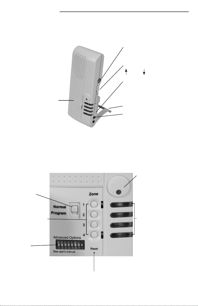
Review detailed product specifications (Fig. 1 and 2)
Door to Programming Controls
Fig. 1
Antenna Jack
· Internal antenna with product
· Use external for maximum range
Volume Control
High Low
Lamp Controller Output
· Works with STI Lamp Controller (STI-30104)
· 3.5mm mono jack, center negative
· 12VDC, 75mA 3 sec
Stand
Power Supply Jack (STI-34105)
· 12 VDC 500mA input
· Switching/regulated
· UL Class II, FCC, C minimum
Program Switch
Zone/Message
Selection Button
· Use to scroll through
default messages
Advanced Programming
Dip Switches
· In PROGRAM mode
switches 3-8 provide
access to 63
messages/tones
Fig. 2
System Reset:
· Clears all programmed zones
- 2 -
Acknowledge Button
· Resets all flashing red zones
· Light flickers green as STI sensor
signal is detected
· Push to silence any auto message
Four Zone Light Indicators
· Solid Red - sensor is triggered
· Flashing Red - zone has triggered
in latching mode. Reset by pushing
acknowledge button, changes back
to green
· Yellow - sensor maintenance
required (tamper, low battery)
· Green - sensor programmed
· No light - sensor not programmed
Page 3

ZONE PROGRAMMING PROCEDURES
Only receives wireless signals from the STI Wireless Alert Series products. Program up to 4
sensors or keyfobs. Does not allow programming into an occupied zone. Cannot program
the same sensor into more than one zone. The unit will state, “Please change to normal
mode if programming is completed.” (Repeats every 60 seconds.) Default language is English.
Move dip switch 1 to the “on” (up) position for Spanish.
MODES OF OPERATION
Set at time of programming by zone
Zone Latching: Dip Switch #2 ‘OFF’
When sensor is triggered, red zone light is solid. “Latching” let’s you know a zone was triggered,
but the alert has cleared (flashing red LED). To reset, push the acknowledge button.
Zone Auto Restore: Dip Switch #2 ‘ON’
“Auto-Restore” sounds when a zone has been triggered. Zone automatically restores to solid
green light without pressing acknowledge button.
Dip Switch Functions
DIP NORMAL MODE PROGRAM MODE
SWITCH
OFF (DOWN) ON (UP) OFF (DOWN) ON (UP)
1 — ENGLISH* SPANISH
2 — LATCHING* AUTO RESTORE
3 PRE-ALERT TONE* NO TONE TONE/WORD SELECT
4 — TONE/WORD SELECT
5 — TONE/WORD SELECT
6 — TONE/WORD SELECT
7 — TONE/WORD SELECT
8 — TONE/WORD SELECT
*Default Mode
- 3 -
CHART 1
Page 4

PROGRAMMING
1. Plug in receiver.
2. Listen to verbal voice commands. They will guide you through programming.
Notes
· Firmly press acknowledge button at any time to stop voice.
· Make sure battery is installed in sensor.
· Each sensor provides an initial sound (DONG).
(See CHART 2 below)
· Each zone button, with programmed sensor, scrolls through default messages using
the zone/message selection button.
· Accept tone/message selected by moving switch to NORMAL mode. These can
be changed at any time by moving the switch to PROGRAM and pushing the
zone/message selection button.
SCROLLING MESSAGE/TONES - Default messages by sensor type
Wireless Stopper® Station Shield, Wireless Exit Stopper® and Wireless Fire Extinguisher Theft
Stopper® will need to use Advanced Programming message codes.
Universal Doorbell Driveway Pool/Entrance Indoor and
Garage Sentry Button Monitor Alert Outdoor
Mailbox Alert PIR
Mailbox Call Front Driveway Pool Door Motion Front
Door Alert Side Driveway Pool Gate Motion Side
Gate Assistance Rear Driveway No Sound* Motion Rear
Window Service No Sound* Ding Motion Driveway
Cover Door Ding Ding Dong Motion Upstairs
Garage Sentry Customer Ding Dong Dong Motion Downstairs
Temperature No Sound* Dong 4-Note Chime Customer
Sump Pump Ding 4-Note Chime 8-Note Chime No Sound*
Freezer Ding Dong 8-Note Chime Knock Ding
Refrigerator Dong Knock Jingle Bells Ding Dong
Water Level 4-Note Chime Jingle Bells Dogs Barking Dong
No Sound* 8-Note Chime Dogs Barking Bell 4-Note Chime
Ding Knock Bell Buzzer 8-Note Chime
Ding Dong Jingle Bells Buzzer Knock
Dong Dogs Barking Jingle Bells
4-Note Chime Bell Dogs Barking
8-Note Chime Buzzer Bell
Knock Buzzer
Jingle Bells
Dogs Barking
Bells
Buzzer
*Zone light indicator still operates
CHART 2
- 4 -
Page 5

ADVANCED PROGRAMMING FOR ALREADY PROGRAMMED SENSORS
3 4 5 6 7 8
0 0 0 0 1 0
3 4 5 6 7 8
0 1 1 1 1 1
3 4 5 6 7 8
0 1 1 0 1 0
(DIP SWITCH 3-8)
Dip Switches 3-8 provide access to all 63 messages/tones which can be assigned to any
zone. Up to 4 messages/tones can be combined to create a custom message. See page 6,
CHART 3, for Advanced Dip Switch Message Codes.
ADVANCED PROGRAMMING
1. Make sure switch is in PROGRAM mode
2. Press zone/message selection button intended for sensor advanced programming
3. Move Dip Switches to correct position for selected word
4. Press zone/message selection button to accept word (repeat for up to four words/tones)
CAUTION – while selecting custom message do not position all Dip Switches back
into OFF (down) position. This will reset your entire message!
5. Move switch to NORMAL mode when complete
6. Test/trigger sensor
Note: If you make a mistake while programming zone custom message, press acknowledge button
to revert to previous message then begin again.
Example of Advanced Programming Message
“(Ding Dong) Customer Service Alert” Four Step Programming
VIEW DIP SWITCH CONTROLS
STEP 1
MESSAGE:
DING DONG
Message Code
ON (UP)
OFF (DOWN)
Dip Switch
MESSAGE CODE MESSAGE
__ __ __ __ __ __ _______________________
__ __ __ __ __ __ _______________________
__ __ __ __ __ __ _______________________
CREATE YOUR OWN CUSTOM MESSAGE
__ __ __ __ __ __ _______________________
Press Zone/Message Selection Button
STEP 2
MESSAGE:
CUSTOMER
0 1 1 1 1 0
3 4 5 6 7 8
Message Code
ON (UP)
OFF (DOWN)
Dip Switch
MESSAGE CODE MESSAGE
__ __ __ __ __ __ _______________________
__ __ __ __ __ __ _______________________
__ __ __ __ __ __ _______________________
__ __ __ __ __ __ _______________________
Press Zone/Message Selection Button
STEP 3
MESSAGE:
SERVICE
Message Code
ON (UP)
OFF (DOWN)
Dip Switch
MESSAGE CODE MESSAGE
__ __ __ __ __ __ _______________________
__ __ __ __ __ __ _______________________
__ __ __ __ __ __ _______________________
__ __ __ __ __ __ _______________________
Press Zone/Message Selection Button
STEP 4
MESSAGE:
ALERT
Press Zone/Message Selection Button
Key: Dip Switch Location
Message Code
ON (UP)
OFF (DOWN)
Dip Switch
MESSAGE CODE MESSAGE
__ __ __ __ __ __ _______________________
__ __ __ __ __ __ _______________________
__ __ __ __ __ __ _______________________
__ __ __ __ __ __ _______________________
- 5 -
Page 6

ADVANCED DIP SWITCH MESSAGE CODES
ALPHABETICAL (ENGLISH)
DIP SWITCH LANGUAGE
3 4 5 6 7 8 English Spanish
0 0 0 1 0 0 4-NOTE CHIME CARILLON DE 4 NOTAS
0 0 0 1 0 1 8-NOTE CHIME CARILLON DE 8 NOTAS
0 1 1 0 1 0 ALERT ALERTA
0 1 1 1 0 1 ASSISTANCE ASISTENCIA
1 1 0 0 0 1 BARN GRANERO
1 0 1 0 1 1 BASEMENT SOTANO
0 0 1 0 0 1 BELL CAMPANA
1 1 0 1 1 1 BUTTON BOTON
0 0 1 0 1 0 BUZZER ZUMBADOR
0 1 0 0 1 1 CABINET GABINETE
0 1 1 0 0 1 CALL LLAMADA
1 1 0 1 0 1 CLOSE CERRAR
1 0 0 0 0 0 COVER CUBIERTA
0 1 1 1 1 0 CUSTOMER CLIENTE
1 0 1 1 1 0 DECK TERRAZA
0 0 0 0 0 1 DING TIMBRE (DIN)
0 0 0 0 1 0 DING-DONG DIN-DON
1 0 0 0 0 1 DOCK MUELLE
0 0 1 0 0 0 DOGS PERROS
0 0 0 0 1 1 DONG TIMBRE (DON)
0 0 1 1 1 0 DOOR PUERTA
1 0 1 0 1 0 DOWNSTAIRS ABAJO
0 1 0 0 0 1 DRIVEWAY ENTRADA
0 1 1 0 0 0 EMERGENCY EMERGENCIA
0 1 0 1 1 1 EXIT SALIDA
0 1 0 1 1 0 EXTINGUISHER EXTINTOR DE INCENDIOS
1 1 1 1 1 1 FOUR CUATRO
1 0 0 1 1 0 FREEZER CONGELADOR
0 0 1 0 1 1 FRONT FRENTE
1 0 1 1 0 1 GARAGE GAREJE
0 0 1 1 1 1 GATE ENTRADA
1 1 0 0 1 1 GUN PISTOL
1 1 0 0 0 0 HALL EL PASILLO
0 0 0 1 1 1 JINGLE BELLS CASCABEL
0 1 1 1 0 0 KEYFOB LLAVERO
1 0 1 1 0 0 KITCHEN COCINA
0 0 0 1 1 0 KNOCK LLAMADA A LA PUERTA
1 1 1 0 0 0 LIQUOR LICOR
0 1 0 0 1 0 MAILBOX BUZON DE CORREO
1 1 0 0 1 0 MEDICINE MEDICINA
0 1 0 1 0 1 MONITOR MONITOR
1 1 1 0 0 1 MOTION MOVIMIENTO
1 1 1 1 0 0 ONE UNO
1 1 0 1 0 0 OPEN ABIERTA
1 0 1 1 1 1 PATIO PATIO
1 0 0 0 1 0 POOL PISCINA
1 1 1 0 1 1 PRE-ALERT PRE-AVISO
1 1 1 0 1 0 PROTECTIVE COVER CUBIERTA PROTECTORA
0 0 1 1 0 1 REAR TRASERA
1 0 0 1 1 1 REFRIGERATOR REFRIGERADOR
0 1 0 1 0 0 SAFE CAJA FUERTE
0 1 1 1 1 1 SERVICE SERVICIO
1 0 0 0 1 1 SHED COBERTIZO
0 0 1 1 0 0 SIDE LADO
1 0 0 1 0 1 SUMP PUMP POZO DE BOMBEO
1 0 0 1 0 0 TEMPERATURE LA TERMPERATURE
0 1 1 0 1 1 THEFT ROBO
1 1 1 1 1 0 THREE TRES
1 1 0 1 1 0 TROUBLE PROBLEMAS
1 1 1 1 0 1 TWO DOS
1 0 1 0 0 1 UPSTAIRS ARRIBA
1 0 1 0 0 0 WATER LEVEL NIVEL DEL AQUA
0 1 0 0 0 0 WINDOW VENTANA
GROUPINGS
DIP SWITCH LANGUAGE
3 4 5 6 7 8 English Spanish
0 0 0 1 0 0 4-NOTE CHIME CARILLON DE 4 NOTAS
0 0 0 1 0 1 8-NOTE CHIME CARILLON DE 8 NOTAS
0 0 1 0 0 1 BELL CAMPANA
0 0 1 0 1 0 BUZZER ZUMBADOR
0 0 0 0 0 1 DING TIMBRE (DIN)
0 0 0 0 1 0 DING-DONG DIN-DON
0 0 1 0 0 0 DOGS PERROS
0 0 0 0 1 1 DONG TIMBRE (DON)
0 0 0 1 1 1 JINGLE BELLS CASCABEL
0 0 0 1 1 0 KNOCK LLAMADA A LA PUERTA
1 1 0 0 0 1 BARN GRANERO
1 0 1 0 1 1 BASEMENT SOTANO
1 0 1 1 1 0 DECK TERRAZA
0 1 0 0 0 1 DRIVEWAY ENTRADA
1 0 0 0 0 1 DOCK MUELLE
1 0 1 0 1 0 DOWNSTAIRS ABAJO
0 0 1 0 1 1 FRONT FRENTE
1 0 1 1 0 1 GARAGE GAREJE
1 1 0 0 0 0 HALL EL PASILLO
1 0 1 1 0 0 KITCHEN COCINA
1 0 1 1 1 1 PATIO PATIO
1 0 0 0 1 0 POOL PISCINA
0 0 1 1 0 1 REAR TRASERA
1 0 0 0 1 1 SHED COBERTIZO
0 0 1 1 0 0 SIDE LADO
1 0 1 0 0 1 UPSTAIRS ARRIBA
0 1 1 0 1 0 ALERT ALERTA
0 1 1 1 0 1 ASSISTANCE ASISTENCIA
0 1 1 0 0 1 CALL LLAMADA
1 1 0 1 0 1 CLOSE CERRAR
0 1 1 1 1 0 CUSTOMER CLIENTE
0 1 1 0 0 0 EMERGENCY EMERGENCIA
0 1 0 1 1 1 EXIT SALIDA
0 1 0 1 1 0 EXTINGUISHER EXTINTOR DE INCENDIOS
0 1 0 1 0 1 MONITOR MONITOR
1 1 1 0 0 1 MOTION MOVIMIENTO
1 1 0 1 0 0 OPEN ABIERTA
1 1 1 0 1 1 PRE-ALERT PRE-AVISO
0 1 1 1 1 1 SERVICE SERVICIO
1 0 0 1 0 0 TEMPERATURE LA TEMPERATURE
0 1 1 0 1 1 THEFT ROBO
1 1 0 1 1 0 TROUBLE PROBLEMAS
1 0 1 0 0 0 WATER LEVEL NIVEL DEL AQUA
1 1 0 1 1 1 BUTTON BOTON
0 1 0 0 1 1 CABINET GABINETE
1 0 0 0 0 0 COVER CUBIERTA
0 0 1 1 1 0 DOOR PUERTA
1 0 0 1 1 0 FREEZER CONGELADOR
0 0 1 1 1 1 GATE ENTRADA
1 1 0 0 1 1 GUN PISTOL
0 1 1 1 0 0 KEYFOB LLAVERO
1 1 1 0 0 0 LIQUOR LICOR
0 1 0 0 1 0 MAILBOX BUZON DE CORREO
1 1 0 0 1 0 MEDICINE MEDICINA
1 1 1 0 1 0 PROTECTIVE COVER CUBIERTA PROTECTORA
1 0 0 1 1 1 REFRIGERATOR REFRIGERADOR
0 1 0 1 0 0 SAFE CAJA FUERTE
1 0 0 1 0 1 SUMP PUMP POZO DE BOMBEO
0 1 0 0 0 0 WINDOW VENTANA
1 1 1 1 0 0 ONE UNO
1 1 1 1 0 1 TWO DOS
1 1 1 1 1 0 THREE TRES
1 1 1 1 1 1 FOUR CUATRO
GROUP
TONOS
TONES
UBICACIONES
LOCATIONS
ALERTAS
ALERTS
OBJECTS
OBJETO
#
- 6 -
CHART 3
Page 7

DELETE SENSOR
1. In PROGRAM mode simultaneously press and hold the acknowledge button and zone/
message selection button for three seconds.
2. Successful when receiver states, “Zone [number] is empty,” and green LED is off.
LOW BATTERY / TAMPER / OUT OF RANGE ALERT
The 4-Zone LED light indicator will turn yellow when maintenance is required on your sensor
(example: low battery or tampering with a sensor). The LED will remain on until the trouble
condition is cleared and a transmission is received. When replacing the battery in a sensor,
you will not need to reprogram into the receiver.
OPTIONAL LAMP CONTROLLER ACCESSORY
The Lamp Controller (STI-30104) plugs into the receiver output jack and will turn on a lamp any
time your sensor is triggered.
MOUNTING OPTIONS
The receiver can be mounted on a wall or set on a table with the provided stand.
WARRANTY INFORMATION
Safety Technology International, Inc. warrants to the original consumer/purchaser that
this product shall be free of defects in material and workmanship under normal use and
circumstances for a period of one (1) year from the original date of purchase.
Electronic warranty form at www.sti-usa.com/wc14.
- 7 -
Page 8

IMPORTANT NOTICE
This product has been tested and complies with the specifications for a Class B digital device, pursuant
to Part 15 of the FCC Rules. These limits are designed to provide reasonable protection against harmful
interference in a residential installation. This equipment generates, uses, and can radiate radio frequency
energy and, if not installed and used according to the instructions, may cause harmful interference to radio
communications. However, there is no guarantee interference will not occur in a particular installation. If
this equipment does cause harmful interference to radio or television reception, which is found by turning
the equipment off and on, the user is encouraged to try to correct the interference by one or more of the
following measures:
· Reorient or relocate the receiving antenna.
· Increase the separation between the equipment and devices.
· Connect the equipment to an outlet other than the receiver’s.
· Consult a dealer or an experienced radio/TV technician for assistance.
Operation is subject to the following two conditions: (1) this device may cause interference, and (2) this
device must accept interference, including interference that may cause undesired operation of the device.
Changes or modifications not expressly approved by Safety Technology International, Inc. could void your
authority to operate this equipment.
To reduce potential radio interference to other users, the antenna type and its gain should be so chosen
that the equivalent isotropically radiated power (e.i.r.p.) is not more than that permitted for successful
communication.
This product meets the applicable industry Canada Technical specifications.
Le present matériel est conformé aux spécifications techniques applicables d’Industrie Canada.
Model: V34104 FCC ID: TXLV34104 IC: 6335A-V34104
This device is a wireless receiver intended for home and office use in all EU and EFTA member states.
TECHNICAL SUPPORT
Contact STI at 800-888-4784
ADDITIONAL WIRELESS ALERT SERIES PRODUCTS
STI-34099 Single Channel Slave Receiver
STI-34104 4-Channel Receiver
STI-V34104 4-Channel Voice Receiver
STI-34108 8-Channel Receiver
STI-34101 Solar Powered Driveway Monitor Sensor
STI-34151 Battery Powered Driveway Monitor Sensor
STI-34201 Wireless Mailbox Alert Sensor
STI-34301 Wireless Garage Sentry Sensor
STI-34401 Wireless Universal Alert Sensor
STI-34501 Wireless Gate Alert Sensor
STI-34601 Wireless Doorbell Button
STI-34701 Indoor Wireless PIR
STI-34751 Outdoor Wireless PIR
STI-6200WIR Wireless Fire Extinguisher Theft Stopper
STI-6200WIR4 Wireless Fire Extinguisher Theft Stopper w/Receiver
STI-6400WIR Wireless Exit Stopper Door Alarm
STI-6400WIR4 Wireless Exit Stopper Door Alarm with Receiver
STI-6517A Stopper Station Shield with Sound
STI-6517B Stopper Station Shield with Sound and Transmitter
STI-30104 Lamp Controller
STI-30105 Extended Antenna
STI-34105 Voltamax 12VDC (500mA) Power Supply
STI-34106 Keyfob
STI-34109 Repeater
STI-34188 8-Zone Relay Board
Printed in USA
Safety Technology International, Inc.
2306 Airport Rd • Waterford, MI 48327
Phone: 248-673-9898 • Fax: 248-673-1246
info@sti-usa.com • www.sti-usa.com
Safety Technology International (Europe) Ltd.
Unit 49G Pipers Road • Park Farm Industrial Estate • Redditch
Worcestershire • B98 0HU • England • Tel: 44 (0) 1527 520 999
Fax: 44 (0) 1527 501 999 • Freephone: 0800 085 1678 (UK only)
E-mail: info@sti-europe.com • Web: www.sti-europe.com
Subject to change without notice.
- 8 -
Inst. V34104 DEC2012
 Loading...