

Page 1
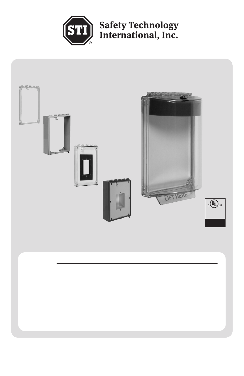
UNIVERSAL STOPPER® SERIES
See Approvals
INSTALLATION INSTRUCTIONS
ADA
Compliant
For Details
Features
· Can be used as a guard against physical damage to a device with or without optional
warning horn.
· Cover locking tab to help prevent tampering.
· Optional horn has choice of 95 or 105 dB at 1 ft.
· Three year guarantee against breakage of polycarbonate in normal use (one year on
electro mechanical and electronic components).
· UL/cUL Listed (Enclosed Flush Backbox model pending).
· ADA Compliant.
· Waterproof Backbox, UL Listed to NEMA Type 3X Standard (pending).
· IP Rating equivalencies.
We protect the things that protect you.
Page 2

Parts Provided (per mounting option)
DESCRIPTION Part No. Qty. Flush Surface Enclosed Enclosed
Backbox
Cover Assembly 1 X X X X
#6 x 1 ¼” Phil Pan Hd Screw 19039 4 X X X X
Plastic Wall Anchor 19018 4 X X X X
Cover Gasket 01316 1 X X X X
Device Mounting Plate 01310 1 X
#6-32 x ½” Phil Flat Hd Screw 19099 6 X
#6 O-ring 01317 4 X
3/4” NPT Plug* 01309 1 X
Solid Insert* 01311 2 X
Conduit Insert* 01312 2 X
1/2” & 3/4” Conduit Weather Gasket STI-6004 2 X
3 Inch Gasket 01318 2 X
#6-32 x 1/2” Phil Pan Hd Screw 19054 2 X
*Available in red, green, blue, yellow, white or black. Inserts also available in clear.
Flush
Backbox
Approvals
It has been tested and approved or listed by:
· Underwriters Laboratories (Enclosed Flush Backbox model pending)
· UL Certified to meet ADA Compliance
· NEMA Type 3X Enclosed Flush Backbox and Backbox (pending)
· IP56 flush, surface and backbox with open mounting plate; IP66 backbox with sealed mounting plate
PATENTS:
United States No. 4,267,549, Canada No. 1,147,828
Specications
Polycarbonate Enclosure
· Flammability - cover and frames: UL 94 V-2, enclosed backbox: UL 94 5VA
· Cover wall thickness 0.12 inches
· Only the BACKBOX mounting options meets NEMA Type 3X (pending)
Gaskets
STI-1316 Cover Gasket - Neoprene 0.070 in. dia.
STI-1318 3” Gasket - Neoprene 1/8” diameter
Mounting Gasket (embedded in housing at STI factory prior to shipping) - Two part polyurethane
STI-1326 1/2” or 3/4” Conduit Weather Gasket - Closed Cell IV-2
Horn 9V (Battery included) 12V 24V
· Low (95 dB @ 1 ft.) 40mA 38mA 22mA
· High (105 dB @ 1 ft.) 105mA 125mA 95mA
· Min. Operating Req. 2V @ 20mA 4V @ 20mA 4V @ 20mA
Dry Contact Relay
· 30 VAC/VDC, 1A
Temperature Range
· Electronics Operating Range: -40° to 120°F (-40° to 49°C) Below -4°F (-20°C), a remote
power source is recommended
· Polycarbonate Rated: -40° to 284°F (-40° to 140°C)
- 2 -
Page 3
Warranty
Three year guarantee against breakage of polycarbonate in normal use (one year on electro
mechanical and electronic components).
Electronic warranty form at www.sti-usa.com/wc14.
Important Notice (when used on fire systems)
The Universal Stopper is intended to be used in areas where the incidence of false fire alarms from
manual pull stations is high or has proven to be a serious problem. Any disadvantage of this device
is more than balanced when one considers the consequences of false fire alarms, especially if fire
service personnel and equipment are responding to a false fire alarm when they are needed for a real
fire somewhere else. Add to this, the disruption to the facility when false alarms occur. If you have,
or may have, a problem with false fire alarms or physical/weather damage to your fire alarm activation
devices, the Universal Stopper could prove invaluable.
Installation Notes
· When used outdoors, the manual pull station must also be rated for outdoor use.
· UL Listing does not permit connection of horn relay contacts to fire alarm or life safety devices.
· According to UL Listing, models powered from an external power source cannot be supplied from
the fire alarm panel.
· When properly installed, the operation of this cover will not interfere with the function of your life
safety system.
· Horn operation and performance must be tested annually. Battery replacement is recommended
annually dependent on usage and battery expiration date.
· Ensure the service pin is properly inserted in the service pin receptor to silence horn while
performing installation or servicing horn.
· If mounting to an uneven surface, a backplate (STI-1314) is recommended to help ensure proper
sealing to mounting surface.
· The backplate may be drilled if wire access or screw mounting holes are needed.
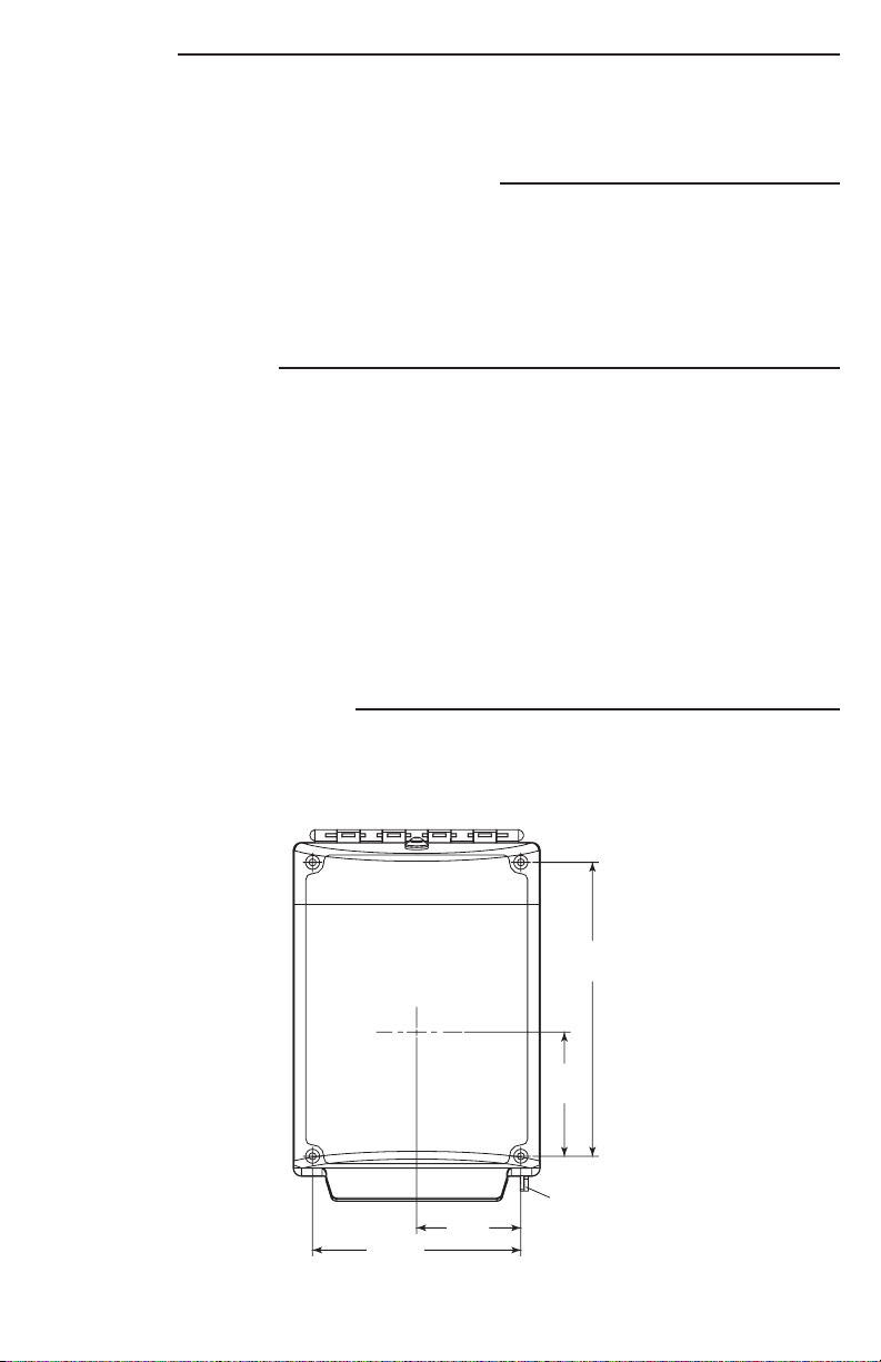
Installation Instructions
1. Center the pull station to the Universal Stopper with the help of the dimensions in Fig. 1. Open
cover and use the mounting frame or optional backplate to mark the mounting hole locations as
in Fig. 1. Be sure the entire cover travel will not interfere with operation of the pull station or
other safety system equipment when installed.
TEXT HERE
6.45 in.
(164mm)
2.73 in.
(69mm)
LIFT HERE
4.58 in.
(116mm)
- 3 -
2.29 in.
(58mm)
LOCKING
TAB
Fig. 1
Page 4

2. If drilling into wood, four #6 x 1 ¼” screws (provided) should be used without anchors and the
DEVICE MOUNTING PLATE
(1) PROVIDED
LOCKING TAB
mounting holes should be drilled 7/64” diameter to a depth of 1 ¼”. If drilling into masonry or
drywall (sheet rock), the wall anchors (provided) should be used and the mounting holes drilled 3/16”
diameter to a depth of 1 ¼”.
3. Refer to Fig. 2, 3 and 4 for illustrations of the different mounting configurations (BACKBOX,
FLUSH, SURFACE). For additional seal reliability, a silicone sealant may be applied between
optional backplate and wall.
4. (For the BACKBOX
mounting option only)
3/4 NPT FOR 3/4 in. CONDUIT
TOP AND BOTTOM
3/4 NPT PLUG
(1) PROVIDED
COVER GASKET
(1) PROVIDED
If routing conduit from
above, run the conduit
through the hole in the
top of the housing.
5. (For the BACKBOX
mounting option only) If
routing from below, use
a flat head screwdriver
or coin to remove the
NPT Plug. Then knock
out a hole in the bottom
and run the conduit
up through the bottom
of the housing. Apply
thread sealant. Screw
the NPT plug back into
DRILL 3/16 DIA. HOLES
1-1/4 in. DEEP (4) PLACES
IF ANCHORS ARE USED
DRILL 7/64 DIA. HOLES
1-1/4 in. DEEP (4) PLACES
IF ANCHORS ARE NOT USED
#6 ANCHOR
(4) PROVIDED
Fig. 2 - BACKBOX MOUNTING OPTION
O-RING GASKET
(4) PROVIDED
#6 x 1-1/4 in. SCREW
(4) PROVIDED
LOCKING
TAB
#6-32 x 1/2 in.
(6) PROVIDED
#6 - 32 x 1/2 in. DEEP
THREADED FOR
MOUNTING DEVICES
DEVICE MOUNTING PLATE
(1) PROVIDED
the threaded top of the
housing.
6. (For the SURFACE mounting option only) Note that the inserts fit flush to the housing only in one
orientation (see Fig. 4). Prior to applying either of the Conduit Weather Gaskets, ensure proper
orientation and fit of the desired inserts from the top or the bottom of the housing.
7. (For the SURFACE mounting option only) After noting the proper insert orientation, fit the appropriate
Conduit Weather Gasket size (1/2” or 3/4”) to the conduit. Then fit the gasket to the Conduit Insert or
directly to the housing knock-out. Repeat this step with the appropriate installation on the opposite.
For additional seal reliability, a bead of silicone may be applied to the conduit fitting.
8. (For the SURFACE mounting option only) Use the 3” gaskets (provided) to complete the seal across
the top and bottom insert locations. Overlap 1/8” of the existing Mounting Gasket on the Universal
Stopper body, run the cord into the preformed channel until it overlaps 1/8” of the opposing Mounting
Gasket. The 3” gasket may need to be trimmed for a proper fit and seal.
9. Align mounting holes in frame to the screw holes made in the wall. If applicable, ensure a proper
seal is made between the wall and
the Mounting Gasket embedded on
the Universal Stopper. If needed, use
OPTIONAL BACKPLATE RECOMMENDED
WHEN MOUNTING TO UNLEVEL SURFACE
optional STI Backplate (STI-1314).
10. (For the BACKBOX mounting option
only) Insert the #6 x 1 ¼” Phillips Pan
LOCKING TAB
Head Screws (provided) into the #6
O-rings STI-01317 (provided) to seal the
Backbox mounting holes.
11. Put the #6 x 1 ¼” Phillips Pan Head
Screws (provided) through the frame
holes into the drilled screw holes and
tighten to mounting surface.
#6 ANCHOR
(4) PROVIDED
DRILL 3/16 DIA. HOLES
1-1/4 in. DEEP WHEN
USING ANCHORS
DRILL 7/64 DIA. HOLES
1-1/4 in. DEEP WHEN ANCHORS
ARE NOT USED
COVER GASKET
(1) PROVIDED
#6 x 1-1/4 in. SCREW
(4) PROVIDED
- 4 -
Fig. 3 - FLUSH MOUNTING OPTION
Page 5

#4 HI-LO SCREW
(2) PROVIDED
WHEN REPLACING COVER
MAKE SURE COVER IS UNDER
HORN CASE TAB AND ROTATE
COVER CLOSED. INSERT HI-LO
SCREWS AND TIGHTEN.
HORN COVER
HIGH/LOW SWITCH
FACTORY DEFAULT HIGH
DETAIL A
12. Make any external connections for remote power or relay options if needed. (When using HORN
LOCKING TAB
option refer to Fig. 5 for wiring details.) 9V battery acts as backup power source when using
remote power.
13. (For BACKBOX mounting option) Place the Device Mounting Plate STI-01310 into the raised wall
area with the horn activation tab oriented sticking up in the upper left. Ensure the wire harness is not
pinched underneath the plate. Use the six #6-32 x ½” screws to secure the Device Mounting Plate to
the housing body.
14. (For BACKBOX mounting option only) Install desired powered device to the mounting screws on the
Device Mounting Plate.
15. Close cover.
16. (When using LOCKING TAB feature) Not for use in fire or emergency signaling applications. With
the cover closed, ensure the locking tabs are overlapping. With the cover remaining closed, drill
a 1/8” hole in the center of the locking tabs.
SOLID INSERT USED WHEN
APPLY A DROP OF SILICONE SEALANT TO HOLD
GASKET IN PLACE. GASKET MAY BE CUT TO OVERLAP
EMBEDDED MOUNTING GASKET IF NECESSARY
3 in. GASKETS (2) PROVIDED.
CONDUIT IS NOT USED
(2) PROVIDED
CONDUIT WEATHER GASKET
USE WITH 1/2 in. OR
3/4 in. CONDUIT (2) PROVIDED
DRILL 3/16 DIA. HOLES
1-1/4 in. DEEP (4) PLACES
HORN CASE
REMOVE BOTH HORN SCREWS AND
ROTATE COVER OPEN AS SHOWN.
Wire
Red
Black
Blue
Green
Yellow
IF ANCHORS ARE USED
DRILL 7/64 DIA. HOLES
1-1/4 in. DEEP (4) PLACES
IF ANCHORS ARE NOT USED
#4 HI-LO SCREW
(2) PROVIDED
Description
+12V - 24V
-12V - 24V
Common
NC - Norm Closed
NO - Norm Open
#6 ANCHOR
(4) PROVIDED
COVER GASKET
(1) PROVIDED
#6 x 1-1/4 in. SCREW
(4) PROVIDED
Fig. 4 - SURFACE MOUNTING OPTION
WHEN REPLACING COVER
MAKE SURE COVER IS UNDER
HORN CASE TAB AND ROTATE
COVER CLOSED. INSERT HI-LO
SCREWS AND TIGHTEN.
HORN COVER
5 CONDUCTOR
WIRE HARNESS
ROTATE BOTTOM END OF BATTERY
UPWARD FOR REMOVAL
Fig. 5
DETAIL A
- 5 -
LOCKING TAB
HOUSING
KNOCK-OUT
A
HIGH/LOW SWITCH
FACTORY DEFAULT HIGH
SERVICE PIN
(1) PROVIDED
Page 6

17. (When using HORN option) Remove the Service Pin and horn should sound. Close cover and
horn should silence.
18. (When using HORN option) To test switch activation, open cover and horn should sound. Close
cover and horn should silence. When performing annual battery test/replacement or whenever
servicing alarm system, insert the Service Pin into the Service Pin Receptor to prevent horn
from sounding. Remember to remove Service Pin to return to normal operation.
19. When using LOCKING TAB feature (not for use in fire or emergency signaling applications), insert
the Breakaway Seal SUB-65 completely into the Locking Tab. Then insert the tip of the Breakaway
Seal into the hole in the Breakaway Seal from the side that reads “ENTER.” Pull the pin through
until tight. Not for use with fire pull stations.
Gasket Installation
Use of gaskets is necessary to ensure a proper seal in weatherproof applications. The Universal
Stopper ships complete with all necessary gaskets and should be used accordingly. The Mounting
Gasket is included on all Universal Stopper products and is embedded in the STI factory prior to
shipping. Two 3” gaskets are shipped with the SURFACE mount Universal Stopper, refer to Step 8 in
the installation instructions. Each 3” gasket is intended to be used with the inserts also shipped with
the SURFACE mount Universal Stopper. To install, the insert should first be fitted in place in the correct
orientation. Then, overlap 1/8” of the existing Mounting Gasket on the Universal Stopper housing, run
the cord into the preformed channel until it overlaps 1/8” of the opposing Mounting Gasket.
Horn Battery Replacement and
Hi/Lo Volume Changing Instructions
1. Obtain the Universal Stopper Service Pin, a small Phillips screwdriver, a 3/32” allen wrench (if
desired) and replacement 9V battery.
2. Open the Universal Stopper cover. The horn should sound. Insert the Service Pin into the Service
Pin Receptor. The horn should silence.
3. (If desired) While holding the horn with one hand, remove the button head screw on the front of the
cover. Then, perform the following actions with the horn separately.
4. Use the Phillips screwdriver to remove the two horn housing cover screws.
5. Replace the battery with a 9V battery only.
6. (If desired) Change the Hi/Lo switch position (Fig. 5, Detail A).
7. Replace the horn housing cover and screws.
8. (To be performed if horn was removed) Orient the horn at the top of the Universal Stopper cover,
and replace the button head screw.
9. Remove the Service Pin and horn should sound. Close cover and horn should silence.
Polycarbonate Cleaning Instructions
Rinse with water to remove abrasive dust and dirt. Wash with soap or mild detergent, using a soft
cloth. Rinse once more then dry with a soft cloth or chamois. Exercise caution when using water
inside enclosure. Make sure unit is completely dry inside before reassembling. To remove grease
or wet paint from exterior of cover, rub gently with a soft cloth thoroughly wetted with Naptha. Then
wash and rinse. Do not use razor blades.
Options Available
Flush
Part Number Description Flush Surface Backbox Backbox
Enclosed
STI-1314 Universal Stopper Backplate X X
STI-6602* Horn Assembly X X X
SUB-319 Wiring harness for remote power X X X
SUB-65 Breakaway Seal (qty. 5) X X X X
EA135 Service Pin X X X
*Available in red, green, blue, yellow, white or black.
- 6 -
Enclosed
Page 7

Product Dimensions
4.08 in.
(104mm)
4.90 in.
(124mm)
2.10 in.
(53mm)
1.69 in.
(43mm)
1.20 in.
(31mm)
2.66 in.
(68mm)
2.54 in.
(64mm)
6.31 in.
(160mm)
5.42 in.
(138mm)
6.80 in.
(173mm)
5.95 in.
(151mm)
4.75 in.
(121mm)
4.00 in.
(102mm)
3.00 in.
(76mm)
EXTERNAL DIMENSIONS
· FLUSH 5.4 W x 8.15 H x 2.66 in. D (137 x 207 x 68 mm)
· SURFACE 5.4 W x 8.15 H x 4.00 in. D (137 x 207 x 102 mm)
· ENCLOSED FLUSH BACKBOX 5.4 W x 8.15 H x 2.8 in. D (137 x 207 x 71 mm)
· ENCLOSED BACKBOX 5.4 W x 8.15 H x 4.00 in. D (137 x 207 x 102 mm)
4.75 in.
(121mm)
4.00 in.
(102mm)
3.00 in.
(76mm)
1.20 in.
(31mm)
1.69 in.
(43mm)
2.10 in.
(53mm)
2.66 in.
(68mm)
2.54 in.
(64mm)
5.42 in.
(138mm)
6.31 in.
(160mm)
4.08 in.
(104mm)
4.90 in.
(124mm)
END VIEW SIDE VIEW
4.75 in.
(121mm)
4.00 in.
(102mm)
3.00 in.
(76mm)
1.68 in.
(43mm)
2.33 in.
(59mm)
4.08 in.
(104mm)
4.90 in.
(124mm)
FLUSH MOUNT DIMENSIONS
3.03 in.
(77mm)
3.44 in.
(87mm)
1.30 in.
(33mm)
2.54 in.
(65mm)
4.00 in.
(102mm)
3.88 in.
(98mm)
6.80 in.
(173mm)
END VIEW SIDE VIEW
5.95 in.
(151mm)
5.42 in.
(138mm)
5.95 in.
(151mm)
6.76 in.
(172mm)
6.31 in.
(160mm)
SURFACE MOUNT DIMENSIONS
-7 -
Page 8

4.08 in.
(104mm)
4.90 in.
(124mm)
2.10 in.
(53mm)
1.69 in.
(43mm)
1.20 in.
(31mm)
2.66 in.
(68mm)
2.54 in.
(64mm)
6.31 in.
(160mm)
5.42 in.
(138mm)
6.80 in.
(173mm)
5.95 in.
(151mm)
4.75 in.
(121mm)
4.00 in.
(102mm)
3.00 in.
(76mm)
1.68 in.
(43mm)
2.33 in.
(59mm)
4.08 in.
(104mm)
4.90 in.
(124mm)
6.31 in.
(160mm)
5.42 in.
(138mm)
5.95 in.
(151mm)
6.76 in.
(172mm)
3.44 in.
(87mm)
3.03 in.
(77mm)
2.54 in.
(65mm)
1.30 in.
(33mm)
4.00 in.
(102mm)
3.88 in.
(98mm)
MOUNTING
4.75 in.
(121mm)
4.00 in.
(102mm)
3.00 in.
(76mm)
5.4 in.
(137mm)
SURFACE
(104mm)
4.9 in.
(124mm)
END VIEW
5.43 in.
(138mm)
4.9 in.
(125mm)
4.75 in.
(121mm)
4.0 in.
(101mm)
3.0 in.
(76mm)
4.08 in.
5.4 in.
(137mm)
4.75 in.
(121mm)
4 in.
(102mm)
3 in.
(76mm)
2.05 in.
(52mm)
3.90 in.
(99mm)
END VIEW
2.54 in.
1.2 in.
(30mm)
1.69 in.
(43mm)
2.1 in.
(53mm)
2.8 in.
(71mm)
(64mm)
6.8 in.
(172mm)
ENCLOSED FLUSH BACKBOX DIMENSIONS
1.74 in.
.84 in.
(21mm)
1.33 in.
(34mm)
(44mm)
1.43 in.
(36mm)
4.00 in.
(102mm)
3.88 in.
(98mm)
1.60 in.
(41mm)
ENCLOSED BACKBOX DIMENSIONS
5.42 in.
(138mm)
5.95 in.
(151mm)
SIDE VIEW
6.31 in.
(160mm)
6.80 in.
(173mm)
6.31 in.
(160mm)
5.42 in.
(138mm)
2.80 in.
(71mm)
5.71 in.
(145mm)
SIDE VIEW
3/4” NPT CONDUIT
HOLE & PLUG
(TOP & BOTTOM)
(1) PROVIDED
2306 Airport Rd • Waterford, MI 48327
Phone: 248-673-9898 • Fax: 248-673-1246
info@sti-usa.com • www.sti-usa.com
Safety Technology International (Europe) Ltd.
Unit 49G Pipers Road • Park Farm Industrial Estate • Redditch
Worcestershire • B98 0HU • England • Tel: 44 (0) 1527 520 999
Fax: 44 (0) 1527 501 999 • Freephone: 0800 085 1678 (UK only)
E-mail: info@sti-europe.com • Web: www.sti-europe.com
7/10
 Loading...