

Page 1
ADA
for operation
UB-2PN Universal 2”
Pneumatic Button
We protect the things that protect you.
Page 2
NO
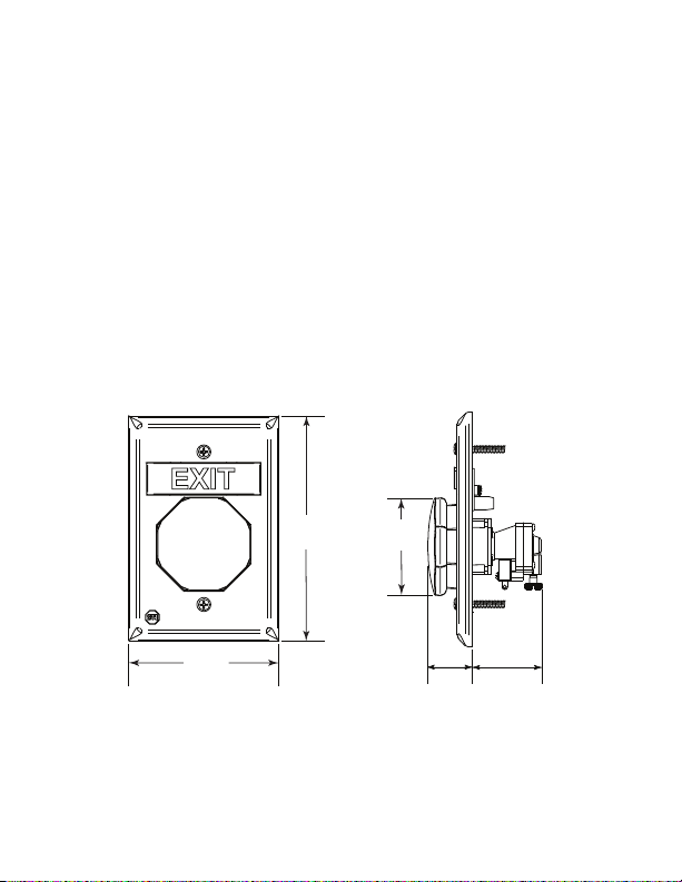
.91 in.
(23mm)
1.47 in.
(38mm)
2 in.
(51mm)
3.22 in.
(82mm)
4.83 in.
(123mm)
TES
I
t
i
s i
mpor
t
ant
t
o r
ead,
under
st
t
hi
s
pr
oduct
NEC,
m
ount
electrical
emer
gency si
el
ect
r
i
cal
ADA
mo
shal
l
not
f
i
ni
shed
copy of
mai
nt
enance
* For
access cont
.
I
t
i
i
ng speci
codes.This
gnal
shock,
u
n
tin
g
c
be
l
ess
f
l
oor
sur
t
hi
s m
of
s
t
o
t
f
t
hi
he
i
i
ng.
DO
mp
lia
han
ace.
anual
s
pr
r
ol
i
nst
f
i
cat
sw
Not
NOT
n
3
1/
Af
t
oduct
nst
al
c
t
al
and and f
l
er’s
r
i
ons accordi
itch
is
t
o be used i
at
t
empt
e
r
e
q
u
2
f
t
.
(
1.
er
i
nst
o al
l
personnel
.
l
at
i
ons,
esponsi
rated
t
o
ir
e
s
th
1m
)
al
l
at
i
on
power
Type
n pl
i
nst
e
or
ol
bi
o
gr
and
l
l
ng t
al
p
e
eat
f
ow al
l
i
nst
t
o
r
compl
i
t
y
o ADA and ot
N
M
(N
l
t
hi
s
r
a
b
le
er
t
est
on-Monitored)
pani
pr
oduct
p
a
r
t
t
han
i
ng
ar
ace of
responsi
or
t
he UB-
uct
i
ons pr
y
wi
t
h
NFP
her appl
c har
dwar
when
o
f
th
e
in
4
1/
2
f
t
.
e
compl
bl
e f
or t
2PN must
ovi
ded wi
A
70
e.
To avoi
power
itia
tin
(
1.
37m)
et
e,
pr
est
i
be suppl
&
101,
i
cabl
for
non-
i
s
on.
g
d
e
v
ic
above
ovi
de
ng and
i
ed
by a power source Listed to UL294. When used for access control, this
de
v
ic
e
s
h
a
ll be
u
se
d
a
s a
p
a
rt o
f a
n
a
c
c
e
ss c
o
n
tro
lle
d
e
g
re
ss d
o
It is u
se
nso
p
to
r. Fo
th
r h
e
lo
c
a
l AHJ
to
a
llo
w u
se
o
f th
is d
e
vic
e
in
p
ig
h
e
r sec
u
rity in
sta
lla
tio
n
s
, lo
wer time
la
limits sh
c
e
o
or system.
f an
automatic
o
u
ld be used.
t
h
e
d
e
a
SWITCH RATING: Independent Form “Z” contacts
Rated at: 10A @ 240 VAC
Operating Temp: 15° to 120°F (-9° to 49°C)
1,000,000 Cycles
- 2 -
Page 3
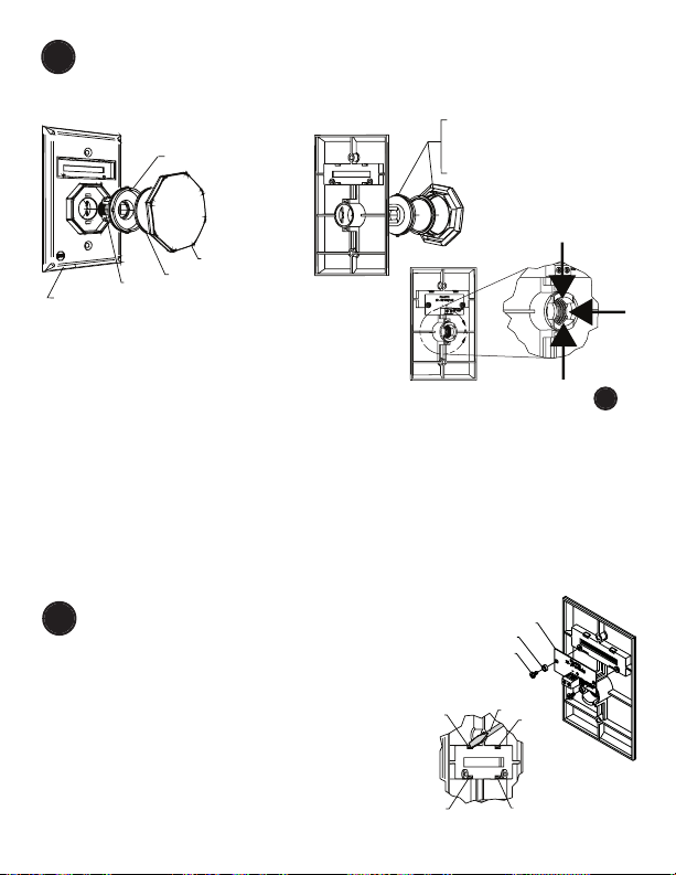
TO CHANGE BUTTON COLOR AND ROUND MESSAGE
1
2
3
4
SCREWDRIVER
UB-1L LED PCB
NYLON WASHER
SCREW
D
IE
C
AS
T
P
L
A
TE
S
P
RIN
G
P
U
S
H
B
U
T
T
O
N
A
C
TUA
T
O
R
A
C
TU
A
T
O
R
C
A
P
2
in
.
B
U
T
T
O
N
A
L
IG
N
T
A
B
O
N
A
C
TUA
T
O
R
W
ITH
S
LOT
B
U
T
T
O
N
.
TU
RN
C
LO
C
K
W
IS
E
T
O
LO
C
K
IN
S
ERT
ASS
EM
B
LY
W
ITH
S
P
RIN
G
IN
T
O
P
L
A
TE.
RE
A
R VIE
W
1
1
2
1
1. Choose button message and color. If same as existing, proceed to
2. To remove push button actuator assembly, squeeze actuator tabs in
direction of #1 arrows.
3. Push acutator through plate in direction of #2 arrow.
4. Align actuator cap to push button actuator. Align button slots to tabs on
push button actuator.
5. Snap button onto push button actuator and rotate right to lock.
6. Insert spring into push button actuator.
7. Squeeze legs of push button actuator and align into die cast plate.
1. Remove LED circuit board.
2.
3.
CHANGE TOP MESSAGE
2
Remove current message by pushing in and
.
down on tabs 1 and 2 with a small screw
driver. If necessary, also push in and down
on tabs 3 and 4. Once message is loose,
remove from the front of the plate.
Select new message and snap into place.
Blank plates are included to create your
own custom message.
- 3 -
-
2
Page 4

P
O
W
E
R
I
N
1
2
-
3
0
V
D
C
/
V
A
C
POWER IN
12-30 VDC/VAC
A
BUTTON ACTIVATED
M
POWER IN
12-30 VDC/VAC
BUTTON ACTIVATED
M
INSTALL OR REMOVE CONTACT BLOCK
3
INSTALL
To attach, align tabs (as shown)
and gently snap top, then bottom.
Be sure to hear BOTH tabs snap
into place. Contacts can be rotated
180° if desired.
DETAIL A
CONTACT INFORMATION
CONTACT REMOVAL
REMOVE
To remove, use a
small flat blade
screwdriver.
Position screwdriver
blade under tab and
gently rotate
screwdriver until tab
disengages. Repeat
for opposite tab.
- 4 -
Page 5

4
OFF
ON
+
+
+
MAG LOCK
NC CONTACTS
NO CONTACTS
UB-1L LED PCB
UL Listed
12-24 VDC Power Supply
NORMAL POSITION BUTTON ACTIVATED
ON
OFF
MAGNETIC LOCK
MESSAGE LAMP
(BLACK) NC
(RED) NO
NC (GREEN)
NO (WHITE)
NC
NO
NC
NO
ATTACH POWER FOR LED (IF DESIRED)
(See drawing)
CONTACT DIAGRAM
One set NO and one set NC
CONTACTS
- 5 -
Page 6

COUNTERCLOCKWISE
CLOCKWISE
TIMER RANGE ADJUSTMENT SCREW
ADJUSTMENT RANGE - 2 TO 60 SECONDS
TIMER FACTORY SET TO MINIMUM TIME
SETTING. TO INCREASE TIME, TURN
SCREW CLOCKWISE IN 1/4 TURN
INCREMENTS. WHEN CLOSE TO DESIRED
TIME, TURN SCREW IN VERY FINE
INCREMENTS TO DESIRED SETTING.
CAUTION: OVER-TIGHTENING MAY
CAUSE DAMAGE TO TIMER.
SWITCH INFORMATION
MOUNT BUTTON ONTO
5
ELECTRICAL BOX
CUSTOM LABELS
6
To create your own custom label, size to fit in .48h x 2.23w as
shown below.
Also available online at: www.sti-usa.com/ublabel
.48 in.
2.23 in.
- 6 -
Page 7

ACCESSORIES
DESCRIPTION
CONTACT BLOCK SUB-UB-1PNC
COLOR MATCH BACK BOX KIT SUB-71100A-COLOR
CUSTOM LABEL APPLIED TO BLANK UB-1CL-COLOR
MESSAGE PLATES (blue, green, white or yellow)
24 VOLT LED
WHITE (STANDARD) 10147
RED 10145
BLUE 10141
GREEN 10143
12 VOLT LED
RED 10144
BLUE 10140
GREEN 10142
COVERS
BOPPER STOPPER STI-6518
UNIVERSAL STOPPER STI-13000 Series
STOPPER II STI-1100 Series
See website for complete cover details
PART #
(
red, blue, green, white or yellow)
- 7 -
Page 8

WARRANTY
Three year guarantee against breakage of polycarbonate in normal use
(one year on electro mechanical and electronic components).
Electronic warranty form at www.sti-usa.com/wc14.
2306 Airport Rd • Waterford, MI 48327
Phone: 248-673-9898 • Fax: 248-673-1246
info@sti-usa.com •
Safety Technology International (Europe) Ltd.
Unit 49G Pipers Road • Park Farm Industrial Estate • Redditch
Worcestershire • B98 0HU • England • Tel: 44 (0) 1527 520 999
Fax: 44 (0) 1527 501 999 • Freephone: 0800 085 1678 (UK only)
E-mail: info@sti-europe.com • Web: www.sti-europe.com
www.sti-usa.com
Printed in USA Inst. Sht. UB-2PN Button JULY2013
 Loading...