

Page 1
ADA
for operation
UB-2 2” Universal Button
UB-2/LTUL Universal Button with Latching Timer
For UB-2/LTUL the enclosed timer is to be used and installed per the enclosed LT1UL installation sheet. For access control installations, power for the LT-1UL Timer
must be supplied by a power source listed to UL294. When used for access control,
this device shall be used as part of an access controlled egress door system. It is
up to the local AHJ to allow use of this device in place of an automatic sensor. For
higher security installations, lower time limits should be used.
We protect the things that protect you.
Page 2
N
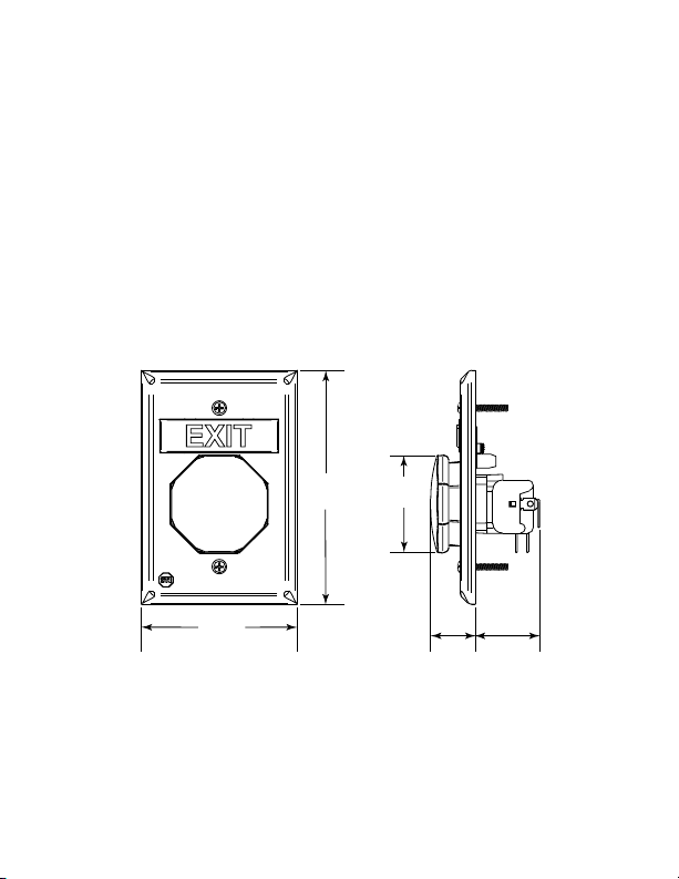
3.22 in.
(82mm)
4.83 in.
(123mm)
2 in.
(51mm)
.9 in.
(24mm)
1.33 in.
(34mm)
O
T
E
S
I
t
i
s
i
m
p
o
r
t
a
n
t
t
o
r
e
a
d
,
u
n
d
e
r
s
t
a
n
d
a
n
d
f
o
l
l
o
w
a
l
l
i
n
s
t
r
u
c
t
i
o
n
s
p
r
o
v
i
d
e
w
i
t
h
t
h
i
s
p
r
o
d
u
c
t
.
I
t
i
s
t
h
e
i
n
s
t
a
l
l
e
r
’
s
r
e
s
p
o
n
s
i
b
i
l
i
t
y
t
o
c
o
m
p
l
y
7
0
&
1
0
1
,
N
E
C
,
m
o
u
n
t
i
n
g
s
p
e
c
i
f
i
c
a
t
i
o
n
s
a
c
c
o
r
d
i
n
g
t
o
p
l
i
c
a
b
l
e
e
l
e
c
t
r
i
c
a
l
c
o
d
e
s
.
F
o
r
T
y
p
e
S
M
(
S
e
l
f
E
m
e
r
g
e
n
c
y
m
e
s
s
a
g
e
m
a
y
b
e
i
n
s
t
a
l
l
t
e
m
w
i
t
h
a
L
i
s
t
e
d
,
c
o
m
p
a
t
i
r
a
t
e
d
T
y
p
e
N
M
(
e
l
e
c
t
r
i
c
a
A
v
(
c
t
l
D
A
m
o
u
i
c
e
s
h
a
l
1
.
3
7
m
)
o
m
p
l
e
t
e
e
s
t
i
n
g
a
N
s
h
o
c
k
,
D
n
l
a
,
n
O
t
i
n
g
c
o
m
n
o
t
b
e
l
b
o
v
e
f
i
n
p
r
o
v
i
d
e
d
m
a
i
n
t
e
b
o
n
-
M
o
n
i
t
N
O
T
a
t
t
p
l
i
a
n
c
e
e
s
s
t
h
a
n
i
s
h
e
d
f
l
o
a
c
o
p
y
o
n
a
n
c
e
o
f
e
l
e
R
e
l
e
a
o
e
r
f
s
r
e
d
)
f
o
r
m
p
t
t
o
i
e
q
u
i
r
e
s
t
3
1
/
2
f
t
o
r
s
u
r
f
a
c
t
h
i
s
m
a
t
h
i
s
p
r
o
d
M
d
o
n
M
o
d
i
n
n
n
h
.
e
n
u
e
g
D
e
v
i
c
e
o
n
-
e
m
e
s
t
a
l
l
t
h
i
s
e
o
p
e
r
a
b
(
1
.
1
m
)
.
A
f
t
e
r
i
n
u
a
l
t
o
a
l
c
t
.
A
o
n
i
t
o
r
e
d
l
U
B
-
1
w
.
A
l
l
o
t
h
r
g
e
n
c
y
s
p
r
o
d
u
c
t
l
e
p
a
r
t
o
o
r
g
r
e
a
s
t
a
l
l
a
t
i
o
l
p
e
r
s
o
n
n
w
D
A
a
n
d
)
h
e
i
w
f
t
e
n
o
r
a
t
i
n
g
,
e
n
u
s
e
d
r
a
p
p
l
i
c
a
g
n
a
l
i
n
g
.
h
e
n
p
o
w
t
h
e
i
n
i
t
i
r
t
h
a
n
a
n
d
t
e
e
l
r
e
s
p
o
n
d
i
t
h
N
F
P
A
t
h
e
r
a
p
-
t
h
e
t
e
r
m
i
n
a
s
y
s
-
t
i
o
n
s
a
r
e
T
o
a
v
o
i
d
e
r
i
s
o
n
a
4
s
.
t
i
n
g
d
e
-
1
/
2
f
t
.
t
i
n
g
a
r
e
s
i
b
l
e
f
o
r
SWITCH RATING
2 Independent Form “C” contacts
UB-2 rated at: 10A, 1/2 HP, 125/250 VAC
6A, 30 VDC
100,000 Operations
Temperature: -40° to 185°F (-40° to 85°C)
- 2 -
Model UB-2/LTUL
Form C contacts on timer rated:
30 VDC 3A, 1.0 pf
Page 3
HANGE
1
1
2
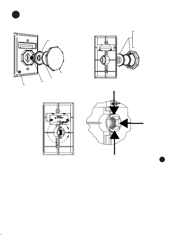
ALIGN TAB ON ACTUATOR
WITH SLOT BUTTON.
TURN CLOCKWISE TO LOCK.
INSERT ASSEMBLY WITH
SPRING INTO PLATE.
DIE CAST PLATE
SPRING
PUSH BUTTON ACTUATOR
ACTUATOR CAP
2 in. BUTTON
C
O
T
1
BUTT
AGE
S
ES
M
UND
RO
AND
R
O
L
O
C
N
O
1. Choose button message and color. If same as existing, proceed to
To remove push button actuator assembly, squeeze actuator tabs in di
2.
rection of #1 arrows.
3. Push acutator through plate in direction of #2 arrow.
4. Align actuator cap to push button actuator. Align button slots to tabs on
push button actuator.
5. Snap button onto push button actuator and rotate right to lock.
2
6. Insert spring into push button actuator.
7. Squeeze legs of push button actuator and align into die cast plate.
- 3 -
-
Page 4

2
1
2
3
4
SCREWDRIVER
UB-1L LED PCB
NYLON WASHER
SELF TAPPING SCREW
HANGE
C
o
t
fer
e
R
1
.
Rem
ov
e L
2
.
R
em
ov
e cur
s
m
all s
cr
O
3
.
S
cr
ew
nce m
es
elect new
eate y
our
ot
n
ED
r
dr
s
age is
m
ow
TO
o
es
cir
ent m
iv
er
es
s
n cus
P
cui
loos
age and s
MESSAGE
r
2 fo
.
g
p
n
t boar
d.
es
s
age by
. If neces
s
e, r
em
nap into place. B
tom
m
es
RGENCY”
E
EM
“
pus
hing in and dow
ar
y
, als
o pus
ov
e fr
om
the fr
s
age.
e us
g
sa
mes
n on tabs
h in and dow
ont of the plate.
lank
plates
e.
1
and 2
n on tabs
ar
e included to
3
and 4
w
ith a
.
- 4 -
Page 5

INSTALL OR REMOVE CONTACT BLOCK
TOP TAB
A
B
STEP A COMP LETED
STEP B
STEP A
STEP C
3
INSTALL
To attach, align tabs (as shown) and gently
snap top, then bottom. Be sure to hear BOTH
tabs snap into place. (Can be reversed if
wiring comes from the top of the box.)
REMOVE
Repeat STEP A for the top and bottom tab before removing contact block.
Step A: Position small flat screwdriver blade under tab and gently rotate
until tab disengages. The contact block will rotate a little. Do NOT pull yet.
Step B: Repeat for opposite tab.
Step C: When both tabs are disengaged, pull the contact block straight off.
- 5 -
Page 6

4
TO SUPERVISED STATION
OR AUXILLARY DEVICE
SW1
SW2
NC
COM
NO
NC
COM
NO
MAG LOCK
MESSAGE LENS PCB
12–24VDC
BUTTON LED
NORMAL POSITION BUTTON ACTIVATED
MAGNETIC LOCK
BUTTON LAMP
MESSAGE LAMP
ON
ON
OFF
OFF
OFF
ON
NO
NC
COM
LED –
LED +
SWITCH 1
SWITCH 2
ATTACH POWER FOR LED (IF DESIRED)
(See drawing)
NOTE
LED connection: The polarity shown is factory installed. LED is
polarity sensitive. If LED does not light, switch positive and negative
wiring or remove LED and rotate 180°. 24 volt is included and will
operate on 12 volts; however not as bright. 12 volt LED’s are also
available.
- 6 -
Page 7

MOUNT BUTTON ONTO ELECTRICAL BOX
19085 #6 - 32 x 1” OVAL
HEAD MACHINE SCREW
(2) PROVIDED
5
6
CUSTOM LABELS
To create your own custom label, size to fit in .48h x 2.23w
area as shown below.
Also available online at: www.sti-usa.com/ublabel
.48 in.
2.23 in.
WARRANTY
Three year guarantee against breakage of polycarbonate in normal use
(one year on electro mechanical and electronic components).
Electronic warranty form at www.sti-usa.com/wc14.
- 7 -
Page 8

ACCESSORIES
DESCRIPTION
CONTACT BLOCK SUB-UB-1C
COLOR MATCH BACK BOX KIT SUB-71100A - COLOR
(
CUSTOM LABEL APPLIED TO BLANK UB-1CL-COLOR
MESSAGE PLATES (blue, green, white or yellow)
24 VOLT LED
WHITE (STANDARD) 10147
RED 10145
BLUE 10141
GREEN 10143
12 VOLT LED
RED 10144
BLUE 10140
GREEN 10142
COVERS
BOPPER STOPPER STI-6518
UNIVERSAL STOPPER STI-13000 Series
STOPPER II
See website for complete cover details
2306 Airport Rd • Waterford, MI 48327
Phone: 248-673-9898 • Fax: 248-673-1246
info@sti-usa.com •
Safety Technology International (Europe) Ltd.
Unit 49G Pipers Road • Park Farm Industrial Estate • Redditch
Worcestershire • B98 0HU • England • Tel: 44 (0) 1527 520 999
Fax: 44 (0) 1527 501 999 • Freephone: 0800 085 1678 (UK only)
Printed in USA Inst. Sht. UB-2 Button DEC2012
E-mail: info@sti-europe.com • Web: www.sti-europe.com
PART #
red, blue, green, white or yellow)
STI-1100 Series
www.sti-usa.com
 Loading...