

Page 1
UB-1TF Universal
Touch Free Button
NoTouch
Technology
We protect the things that protect you.
®
Page 2
NOTES
It is important to read, understand and follow all instructions provided with
this product. It is the installer’s responsibility to comply with NFPA 70 &
101, NEC, mounting specifications according to ADA and other applicable
electrical codes. To avoid electrical shock, DO NOT attempt to install
this product when power is on. ADA mounting compliance requires the
operable part of the initiating device shall not be less than 3 1/2 ft. (1.1m ) or
greater than 4 1/2 ft. (1.37m) above finished floor surface. After installation
and testing are complete, provide a copy of this manual to all personnel
responsible for testing and maintenance of this product.
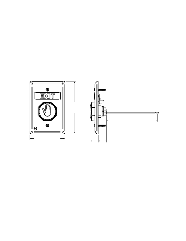
4.80 in.
(122mm)
6.25 in.(159mm)
3.22 in.(82mm)
.77 in.
(20mm)
POWER
Switch:
Input: 12 VDC ± 15%
Standby Power: 15 mA
Active: 25 mA
Operating temperature:
-4° to 158°F (-20° to 70°C)
Message LED:
12-24 VDC
Form “C” contact rating:
30 VDC, 1A
- 2 -
.75 in.
(19mm)
Page 3
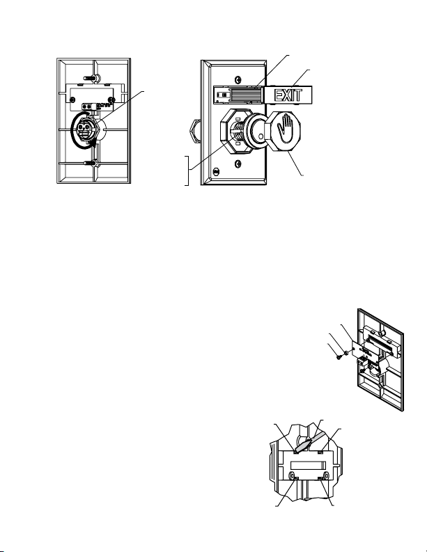
1. TO CHANGE BUTTON COLOR AND ROUND MESSAGE
1
2
3
4
SCREWDRIVER
DIFFUSER
MESSAGE LENS
POWER IN
12-30 VDC/VAC
œ
+
1. Choose button color. If same as existing, proceed to 2.
2. a. Loosen nut on back of switch, and push switch through plate far
enough to grasp button from back edge and remove button lens.
b. Push switch back into plate and tighten nut. Be careful not to over-
tighten.
3. Select color lens. Align notches on button with tabs on switch and push until it
snaps together.
SWITCH NUT
ALIGN TABS
TO NOTCHES
ON BUTTON
LENS
BUTTON LENS
2. CHANGE TOP MESSAGE
(Refer to notes on pg. 2 for “EMERGENCY”
message use.
1. Remove LED circuit board.
2. Remove current message by pushing in and
down on tabs 1 and 2 with a small screwdriver.
If necessary, also push in and down on tabs 3
and 4. Once message is loose, remove from the
front of the plate.
3. Select new message and snap into place.
Blank plates are included to create your own
custom message.
- 3 -
UB-1L LED PCB
NYLON WASHER
SELF TAPPING SCREW
1
3
SCREWDRIVER
2
4
Page 4

12-30 VDC/VAC
œ
+
ALIGN TABS
TO NOTCHES
ON BUTTON
LENS
BUTTON LENS
CONTACT LATCH TIME ADJUSTMENT:
CLOCKWISE - LONG
COUNTERCLOCKWISE - SHORT
RANGE: ~0.5 ~ 60 sec.
4.80 in.
(122mm)
3.22 in.(82mm)
6.25 in.(159mm)
.75 in.
(19mm)
.77 in.
(20mm)
3. ATTACH WIRE PLUG
Wire Color Code with power applied:
Red: +12 VDC
Black: -12 VDC
Green: N.C.
Blue: COM
White: N.O.
CONTACT LATCH TIME ADJUSTMENT:
CLOCKWISE - LONG
COUNTERCLOCKWISE - SHORT
RANGE: ~0.5 ~ 60 sec.
PO
1
WER IN
2-
30 VDC/V
œ +
A
C
A
INSERT PLUG INTO SWITCH WITH
RIBS IN THIS DIRECTION
ACTIVATION RANGE ADJUSTMENT:
CLOCKWISE - CLOSE
COUNTERCLOCKWISE - FAR
RANGE: ~0.4 ~ 4 INCHES
~1 ~ 10 CM
- 4 -
DETAIL A
Page 5

4. ATTACH POWER FOR MESSAGE LED (if desired)
WIRING DIAGRAMS (Color codes are shown with power applied and button LED red during
wiring)
A. Normally Open Exit Device
Message lit with button LED red
BLUE
RED
N.C.
COM
N.O.
GND
+12VDC
UB-1TF LED
GREEN
WHITE
BLACK
EXIT
DEVICE
INPUT
Message lit with button LED green
RED
N.C.
COM
N.O.
GND
+12VDC
UB-1TF LED
GREEN
BLUE
WHITE
BLACK
EXIT
DEVICE
INPUT
B. Normally Closed Exit Device
Message lit with button LED red
BLUE
RED
N.C.
COM
N.O.
GND
+12VDC
UB-1TF LED
GREEN
WHITE
BLACK
EXIT
DEVICE
INPUT
Message lit with button LED green
RED
N.C.
COM
N.O.
GND
+12VDC
UB-1TF LED
GREEN
BLUE
WHITE
BLACK
EXIT
DEVICE
INPUT
UB-1TF Wire Color Code
CONNECTOR POWER OFF POWER ON POWER ON
WIRE COLOR (SUPERVISORY) UNTRIGGERED TRIGGERED
RED +12V +12V +12V
BLACK -12V -12V -12V
GREEN N.O. N.C. N.O.
BLUE COM COM COM
WHITE N.C. N.O. N.C.
LED color None Red Green
- 5 -
Page 6

DETAIL A
UB-1L LED PCB
NYLON WASHER
SELF TAPPING SCREW
Power In
12œ30 VDC/VAC
CONTACT LATCH TIME ADJUSTMENT:
CLOCKWISE - LONG
COUNTERCLOCKWISE - SHORT
RANGE: ~0.5 ~ 60 sec.
ACTIVATION RANGE ADJUSTMENT:
CLOCKWISE - CLOSE
COUNTERCLOCKWISE - FAR
RANGE: ~0.4 ~ 4 INCHES
~1 ~ 10 CM
5. MOUNT BUTTON ONTO ELECTRICAL BOX
19085 #6 - 32 x 1 in. OVAL
HEAD MACHINE SCREW
(2) PROVIDED
6. CUSTOM LABELS
To create your own custom label, size to fit in .48h x 2.23w as shown below.
Also available online at: www.sti-usa.com/ublabel
.48 in.
2.23 in.
- 6 -
Page 7

ACCESSORIES
DESCRIPTION PART #
COLOR MATCH BACKBOX KIT SUB-71100A - COLOR
CUSTOM LABEL APPLIED TO BLANK UB-1CL-COLOR
MESSAGE PLATES
24 VOLT LED
WHITE (STANDARD) 10147
BOPPER STOPPERSTI-6518
UNIVERSAL STOPPERSTI-13000 Series
See website for complete cover details
RED 10145
BLUE 10141
GREEN 10143
12 VOLT LED
RED 10144
BLUE 10140
GREEN 10142
COVERS
STOPPER II STI-1100 Series
red, blue, green, white or yellow)
(
(blue, green, white or yellow)
- 7 -
Page 8

WARRANTY
Three year guarantee against breakage of polycarbonate in normal use (one year on
electro mechanical and electronic components).
Electronic warranty form at www.sti-usa.com/wc14.
2306 Airport Rd • Waterford, MI 48327
Phone: 248-673-9898 • Fax: 248-673-1246
info@sti-usa.com • www.sti-usa.com
Safety Technology International (Europe) Ltd.
Unit 49G Pipers Road • Park Farm Industrial Estate • Redditch
Worcestershire • B98 0HU • England • Tel: 44 (0) 1527 520 999
Fax: 44 (0) 1527 501 999 • Freephone: 0800 085 1678 (UK only)
E-mail: info@sti-europe.com • Web: www.sti-europe.com
Printed in USA Inst. Sht. UB-1TF Button MARCH2010
 Loading...