

Page 1
ADA
for operation
UB-1 Universal Button
UB-1/LTUL Universal Button with Latching Timer
NOTE For UB-1/LTUL the enclosed timer is to be used and installed per the
enclosed LT-1UL installation sheet. For access control installations, power for
the LT-1UL Timer must be supplied by a power source listed to UL294. When
used for access control, this device shall be used as part of an access controlled
egress door system. It is up to the local AHJ to allow use of this device in place
of an automatic sensor. For higher security installations, lower time limits should
be used.
We protect the things that protect you.
Page 2
NOT
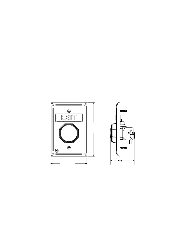
4.830 in.
(123mm)
3.220 in.
(82mm)
1.328 in.
(34mm)
.867 in.
(22mm)
ES
It
is import
wi
th thi
70 & 101, N
pl
icabl
E
m
ergen
te
m
ra
ted
el
ect
A
D
A
v
i
c
e
(1.
37m
w
rica
m
s
e el
i
th
Typ
o
hal
s
p
ect
cy
a
e N
l
sh
un
ti
l not b
) ab
a
nt
ro
d
EC, m
m
L
i
ste
M (N
ock
ng
ov
t
uc
rical
es
,
c
e fi
o r
sage
d
o
e
ea
d,
t
.
It i
s
o
un
ti
codes. F
m
,
comp
o
n-Mo
D
O
NOT
m
p
li
anc
less
than 3
ni
s
hed
u
n
de
the i
ng
s
or Type SM
ay
be
a
ti
b
ni
to
att
e
f
lo
rst
ns
tal
p
ec
in
l
e
Re
red
empt
req
ui
1
o
r
s
a
ler
i
fi
s
t
alled
l
) fo
res
/2
ur
n
d a
n
d foll
o
w
a
ll
in
st
ru
ct
ion
s pr
o
v
g, t
l
ic
ng
po
ni
tes
ed
th N
other
h
e t
in
a
ti
ons
.
T
o
wer
ti
a
ti
ng
1
ti
ng
ide
F
PA
ap
erm
a
sys
a
a
v
o
is
on
d
/2
ft
are
’
s
res
p
o
ns
i
b
i
li
ty to
c
o
m
p
y
ct
t
e
ti
AD
wh
s
i
w
of
a
te
o
n and
A and
r
at
in
en
us
r
a
p
p
g
nali
h
en
the
r
than 4
ly wi
i
c
a
ti
o
ns
ac
c
o
rd
i
ng
f M
o
del
i
t
h
is
erab
m
) or
i
on
ce
erg
produ
le
ns
to
it
ored)
U
B
-1
.
A
ll
othe
enc
p
ar
g
r
tal
la
(
Sel
o
n
M
e
a
si
ng
D
ev
r
no
n-
o
ft
fac
in
the
e.
.
st
(1
A
em
a
ll
op
.
1
f
ter
t
complete, provide a copy of this manual to all personnel responsible for
testing and maintenance of this pr
oduct.
d
-
-
r
e
i
d
.
e
.
SWITCH RATING
2 Momentary Independent Form “C” contacts
UB-1/rated at: 10A, 1/2 HP, 125/250 VAC
6A, 30 VDC
100,000 Operations
Temperature: -40° to 185°F (-40° to 85°C)
- 2 -
Model UB-1/LTUL
Form C contacts on
Timer rated:
30 VDC 3A, 1.0 pf
Page 3
TO
Power In
12–30 VDC/VAC
Safety Tech. Int’l Inc.
P/N UB-11. Ver 1.0
w
wyy
DIFFUSER
BUTTON ACTIVATED
M
UB-1L LED PCB
1
2
3
4
SCREWDRIVER
UB-1L LED PCB
NYLON WASHER
SELF TAPPING SCREW
CHA
NG
E B
UTTO
N C
O
L
O
R
A
ND RO
1
UND MESSAG
E
1.
C
hoose button message and color. If same as existing, pr
2.
If choosing a new message, rem
p
la
te
len
s
3
.
C
ho
o
m
e
s
s
a. I
b
C
HANGE TOP MESSAGE
2
Refer to
“EM
1.
Remove LED circuit board.
2.
Remove current message by pushing in
, p
u
s
h a
scre
a
n
d
b
u
tto
n m
s
e
b
u
t
to
n
a
m
ge
.
n
se
rt
bu
. S
e
lec
t c
a
c
tu
ato
r a
not
es o
ERGENCY” messa
w
d
riv
e
r thro
es
sa
g
e o
e
s
s
a
g
e. Bla
tt
o
n
m
es
s
o
lo
r le
ns
. Align t
nd
p
u
s
h
n
pg. 2 fo
ge use.
and down on tabs 1 and 2 with a small
screwdriver. If necessary, also push in and
down on tabs 3 and 4. Once message is
loose, remove from the front of the plate.
3.
Select new message and snap into place.
Blank plates are included to create your
own custom message.
oceed to
o
ve
butto
n
. On
the
ba
ck
s
ide
u
gh
the
ac
tua
to
ff.
n
k
pla
te
is
ag
e
, alig
n 4
o
p
u
an
n
til it
sn
aps
r
- 3 -
n
d b
a
otc
to
va
ila
he
o
tt
om notc
ge
r t
b
le
s
o
th
e
unn
f
o
n
a
r
.
r y
c
h
e
l a
t
u
es w
ou
n
r c
a
t
d f
o
us
or
.
it
h tabs on
of the
rce the
tom
2
Page 4

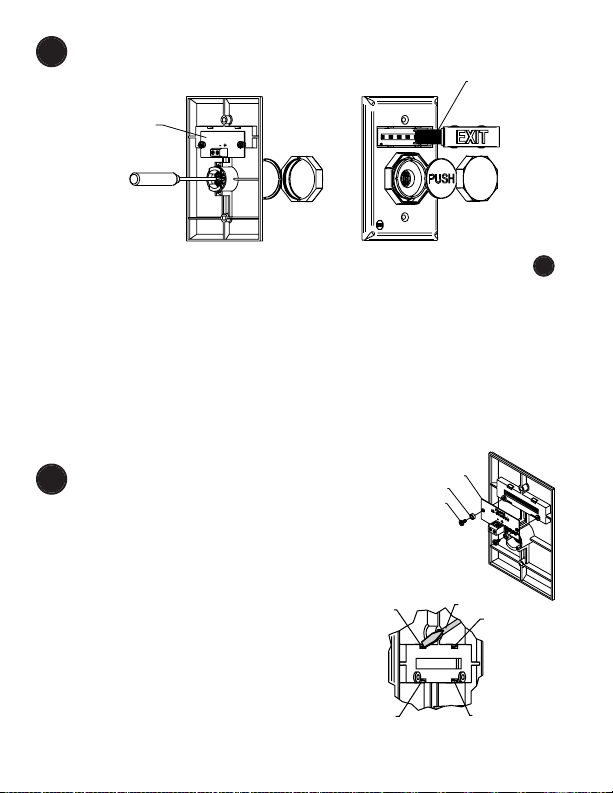
INSTALL OR REMOVE CONTACT BLOCK
TOP TAB
A
B
STEP A COMPLET ED
STEP B
STEP A
STEP C
3
INSTALL
To attach, align tabs (as shown) and gently
snap top, then bottom. Be sure to hear BOTH
tabs snap into place. (Can be reversed if
wiring comes from the top of the box.)
REMOVE
Repeat STEP A for the top and bottom tab before removing contact block.
Step A: Position small flat screwdriver blade under tab and gently rotate
until tab disengages. The contact block will rotate a little. Do NOT pull yet.
Step B: Repeat for opposite tab.
Step C: When both tabs are disengaged, pull the contact block straight off.
- 4 -
Page 5

4
TO SUPERVISED STATION
OR AUXILLARY DEVICE
SW1
SW2
NC
COM
NO
NC
COM
NO
MAG LOCK
MESSAGE LENS PCB
12–24VDC
BUTTON LED
NORMAL POSITION BUTTON ACTIVATED
MAGNETIC LOCK
BUTTON LAMP
MESSAGE LAMP
ON
ON
OFF
OFF
OFF
ON
NO
NC
COM
LED –
LED +
SWITCH 1
SWITCH 2
ATTACH POWER FOR LED (IF DESIRED)
(See drawing)
NOTE
LED connection: The polarity shown is factory installed. LED is
polarity sensitive. If LED does not light, switch positive and negative
wiring or remove LED and rotate 180°. 24 volt is included and will
operate on 12 volts; however not as bright. 12 volt LED’s are also
available.
- 5 -
Page 6

5
DRILL OUT THE (4) MOUNTING
HOLES, ONE IN EACH CORNER,
USING 5/32 in. DRILL BIT
BACKBOX MUST BE MOUNTED
WITH ARROWS POINTING UP
.867 in.
(22mm)
1.575 in.
(40mm)
19018 ANCHOR
(4) PROVIDED
DRILL POINT PROVIDED TOP & BOTTOM
FOR 1/2 in. CONDUIT. DRILL AS NEEDED.
19039 SCREW
#6 x 1 1/4 in.
(4) PROVIDED
DRILL (4)
3/16 in.
DIAMETER HOLES
71100A
BACKBOX
19085 #6-32 x 1 in.
OVAL HEAD MACHINE SCREW
(2) PROVIDED
SURFACE MOUNT OPTION
- 6 -
Page 7
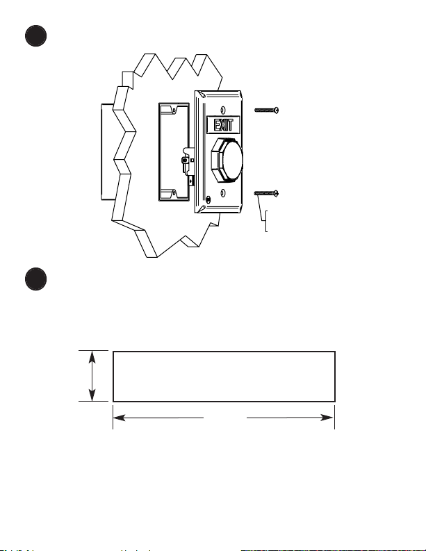
MOUNT BUTTON ONTO ELECTRICAL BOX OPTION
19085 #6 - 32 x 1” OVAL
HEAD MACHINE SCREW
(2) PROVIDED
6
CUSTOM LABELS
7
To create your own custom label, size to fit in .48h x 2.23w
as shown below.
Also available online at: www.sti-usa.com/ublabel
.48 in.
2.23 in.
WARRANTY
Three year guarantee against breakage of polycarbonate in normal use
(one year on electro mechanical and electronic components).
Electronic warranty form at www.sti-usa.com/wc14.
- 7 -
Page 8

ACCESSORIES
PART #
DESCRIPTION
SUB-UB-1C CONTACT BLOCK
SUB-71100A-COLOR COLORMATCH BACKBOX KIT
(red, blue, green, white or yellow)
UB-1CL-COLOR CUSTOM LABEL APPLIED TO
(blue, green, white or yellow) BLANK MESSAGE PLATES
24 VOLT LED
10147 WHITE (STANDARD)
10145 RED
10141 BLUE
10143 GREEN
12 VOLT LED
10144 RED
10140 BLUE
10142 GREEN
COVERS
STI-6518 BOPPER STOPPER
STI-13000 SERIES UNIVERSAL STOPPER
STI-1100 SERIES STOPPER II
SE E WE BS IT E FO R C OM PL ET E COV ER D ETAI LS
2306 Airport Rd • Waterford, MI 48327
Phone: 248-673-9898 • Fax: 248-673-1246
info@sti-usa.com •
www.sti-usa.com
Safety Technology International (Europe) Ltd.
Unit 49G Pipers Road • Park Farm Industrial Estate • Redditch
Worcestershire • B98 0HU • England • Tel: 44 (0) 1527 520 999
Fax: 44 (0) 1527 501 999 • Freephone: 0800 085 1678 (UK only)
E-mail: info@sti-europe.com • Web: www.sti-europe.com
Printed in USA Inst. Sht. UB-1 Button DEC2012
 Loading...