

STI Stopper II, Stopper II STI-1200A-HTR, Stopper II STI-1200A-HTR240 Series Manual
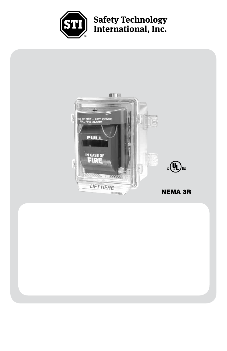
Stopper II® Heated Enclosure
(Outdoor Models)
STI-1200A-HTR
STI-1200A-HTR240
ADA
Compliant
· Maintains initiating device temperature with external temperatures to -70°F
(-57°C). Independently tested to -102°F (-73°C).
· Protects initiating devices for addressable units to UL 38 Standards.
· The clear, protective polycarbonate cover is UV-stabilized against discoloration.
· Enclosure rated to NEMA 3R Standards to provide a degree of protection
against rain, sleet, and damage from external ice formation.
· Fan runs continuously to maintain a uniform temperature inside the enclosure.
· Heater units cycle as required to maintain the correct range of operating
temperatures.
· Three year guarantee against breakage of polycarbonate in normal use (one
year on electro mechanical and electronic components).
· UL/ULC Listing does not require standby or secondary power for 110 or 240
VAC 50/60 Hz heater.
We protect the things that protect you.
®

Warnings and Installation Notes
The enclosure is used to protect UL Listed 38 and 2017 initiating devices at temperatures down to -70˚F (-57˚C). It is the installer’s responsibility
to comply with NEC 70 Articles 725 and 760, NFPA 72, and other applicable fire and electrical codes. Conduit or raceway paths need to be sealed
as near to the enclosure as possible. Installer should have maintained supervision over the low temperature thermostat. The low temperature
monitoring thermostat makes the circuit at +32°F (0°C) and clears the circuit at +50°F (+10°C). This listing requires that the fire alarm supervisory
control module be only of the latching type. On the appliance mounting plate is a label where you should record the installation date. Also include
below the serial number and installation date on the instruction sheet for quick reference.
Serial Number__________________________________ Installation Date__________________
NOTE: Operating voltage for the STI-1200A-HTR is 110 VAC. Operating voltage for the STI-1200A-HTR240 is 240 VAC.
1. Use of an outdoor rated initiating station is required with this heated enclosure.
2. When conducting periodic testing, if conditions are dusty or if you have wind blown dust conditions, cover return grill ports to
minimize entrance of dust or sand particles. To remove accumulated dust or sand particles, use small containers of compressed
air that is used for electronic cleaning.
3. To reset the thermal circuit breaker push button.
If circuit breaker will not remain in a restored or closed position, conduct an electrical check of the various components in
the two voltage classes. The two voltage classes are 24 VDC Negative Ground and 110 or 240 VAC 50-60 Hz with connected
electrical or earth ground. High voltage (110 or 240 VAC) wiring must enter through bottom conduit. Low voltage and signaling
wires must enter through top conduit and remain separated per NFPA 70, NEC, and local codes.
4. If the thermal circuit breaker has tripped (opened circuit), the 110 or 240 VAC 50-60 Hz power will still be energized up to the
primary side of the thermal breaker. For safety, disconnect supply power of conductors to three power circuits in the enclosure.
5. To clean 24 VDC negative ground fan with electronic compressed air container, disconnect all power.
Note: the 24 VDC negative ground fan will not operate if positive and negative conductors are connected on the wrong terminals.
6. To minimize arid summer time heat build up in enclosure, install a dark color sun shield with sides to provide shade for the
enclosure. At the inclined face above the enclosure at the point of contact with the building structure leave at least 1/2”
or (1.25 cm) space. This will generate heat and cause an upward airflow and help maintain the enclosure temperature
approximately the same as ambient air temperature.
7. The 110 or 240 VAC single phase 50-60 Hz heater does not require standby or secondary power because the enclosure
environment is supervised by a latching supervisory circuit in the alarm control unit or panel.
8. Replacement of heater assembly and gasket is required five years from installation date. Contact STI to order replacement
Heater Kit STI-HK3.
9. All field wiring within this enclosure must be rated for a minimum operating range of 0ºC - 110ºC.
Mises en garde et remarques sur l’installation
Le boîtier est utilisé pour protéger les dispositifs de déclenchement homologués UL 38 et 2017 à des températures allant jusqu’à -70 °F (-57 °C).
Il incombe à l’installateur de se conformer aux articles 725 et 760 de la NEC 70, NFPA 72, et aux autres codes de prévention des incendies et de
l’électricité en vigueur. Les chemins des conduites ou canalisations doivent être scellés aussi proche que possible du boîtier. Il est attendu que
l’installateur ait effectivement contrôlé le thermostat à basse température. Le contrôle du thermostat à basse température maintient le circuit à
32 °F (0 °C) et déclenche le circuit à 50 °F (10 °C). Cette homologation exige nécessite que le module de contrôle de la surveillance des alertes
d’incendie soit uniquement du type à verrouillage. La plaque de montage de l’appareil comporte une étiquette sur laquelle vous devez enregistrer
sa date d’installation. Le numéro de série et la date d’installation doivent aussi être marqués sur la feuille d’instruction pour référence rapide.
Numéro de série ____________________ Date d’installation ______________
REMARQUE: La tension de service du STI-1200A-HTR est de 110 VCA. La tension de service du STI-1200A-HTR240 est de 240 VCA.
1. Use of an outdoor rated initiating station is required with this heated enclosure.
2. When conducting periodic testing, if conditions are dusty or if you have wind blown dust conditions, cover return grill ports to minimize entrance of
dust or sand particles. To remove accumulated dust or sand particles, use small containers of compressed air that is used for electronic cleaning.
3. To reset the thermal circuit breaker push button.
If circuit breaker will not remain in a restored or closed position, conduct an electrical check of the various components in the two voltage classes.
The two voltage classes are 24 VDC Negative Ground and 110 or 240 VAC 50-60 Hz with connected electrical or earth ground. High voltage (110
or 240 VAC) wiring must enter through bottom conduit. Low voltage and signaling wires must enter through top conduit and remain separated
per NFPA 70, NEC, and local codes.
4. If the thermal circuit breaker has tripped (opened circuit), the 110 or 240 VAC 50-60 Hz power will still be energized up to the primary side of
the thermal breaker. For safety, disconnect supply power of conductors to three power circuits in the enclosure.
5. To clean 24 VDC negative ground fan with electronic compressed air container, disconnect all power.
Note: the 24 VDC negative ground fan will not operate if positive and negative conductors are connected on the wrong terminals.
6. To minimize arid summer time heat build up in enclosure, install a dark color sun shield with sides to provide shade for the enclosure. At the
inclined face above the enclosure at the point of contact with the building structure leave at least 1/2” or (1.25 cm) space. This will generate heat
and cause an upward airflow and help maintain the enclosure temperature approximately the same as ambient air temperature.
7. The 110 or 240 VAC single phase 50-60 Hz heater does not require standby or secondary power because the enclosure environment is
supervised by a latching supervisory circuit in the alarm control unit or panel.
8. Replacement of heater assembly and gasket is required five years from installation date. Contact STI to order replacement Heater Kit STI-HK3.
9. All field wiring within this enclosure must be rated for a minimum operating range of 0ºC - 110ºC.
- 2 -
Polycarbonate Cleaning Instructions
Rinse with water to remove abrasive dust and dirt. Wash with soap or mild detergent, using a soft
cloth. Rinse once more, then dry with a soft cloth or chamois. Exercise caution when using water inside
enclosure. Make sure unit is completely dry inside before reassembling. Do not use razor blades.
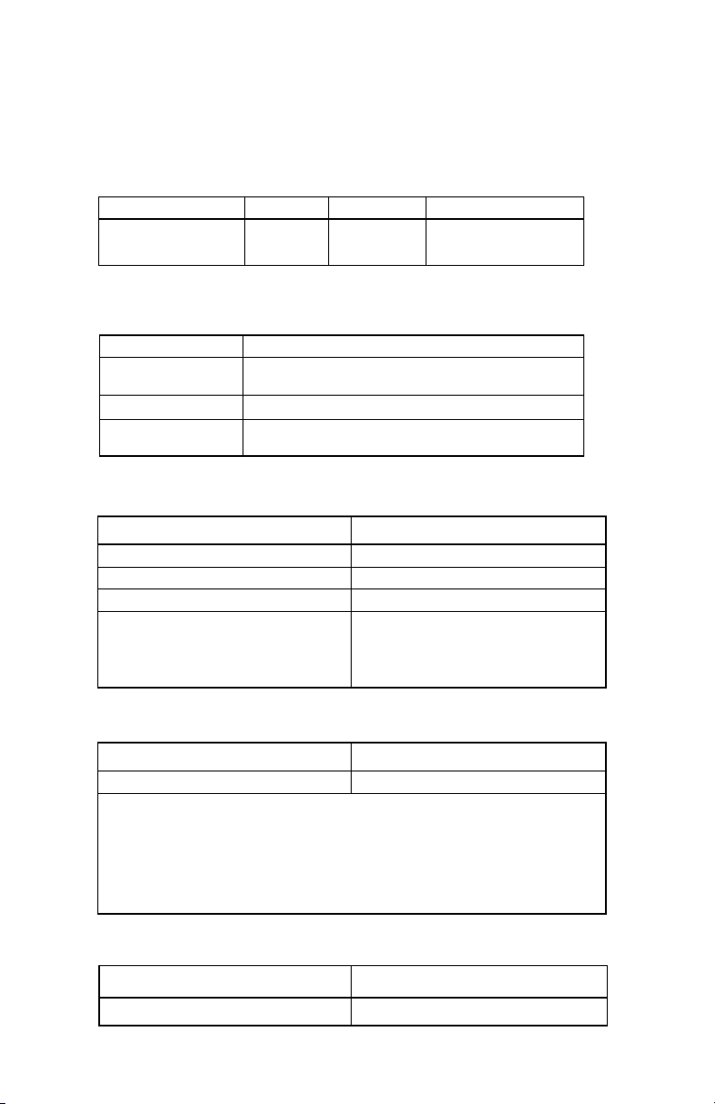
Specications
Internal Dimensions
PART # HEIGHT WIDTH DEPTH
1200A-HTR 6.25 in. 4.125 in. 1.25 in.
1200A-HTR240 (158mm) (104mm) (31mm)
Polycarbonate Enclosure
Flammability UL94 V-2
Wall Thickness back box: .20 inches (5.1mm)
cover: .12 inches (3.1mm)
NEMA Rating 3R
Warranty Lifetime against breakage in normal use.
Silicone Laminate Heater
STI-1200A-HTR 110 VAC 50/60 Hz UL Recognized Component
STI-1200-A-HTR240 240 VAC 50/60 Hz UL Recognized Component
100 Watts
Life: @-10°C (14°F) ~ 70°C (158°F) 5 Years
Duty Cycle: -40°F (-40°C) 16%
-79°F (-57°C) 38%
-99°F (-73°C) 100%
Fan
24 VDC (±10%), 90 mA UL Recognized Component
Life 5 Years Continuous Duty
WARNING: The polarity of the circulating fan is important as it only rotates in one
direction with red lead being positive.
MISE EN GARDE: La polarité du ventilateur de circulation est importante car il ne tourne
que dans un sens avec son fil rouge étant celui du pôle positif.
Gasket
Material Neoprene
Life 5 Years
- 3 -
 Loading...