

Page 1
StopperSwitch SS3000 Series
1
2
3
4
1
2
3
4
1
2
3
4
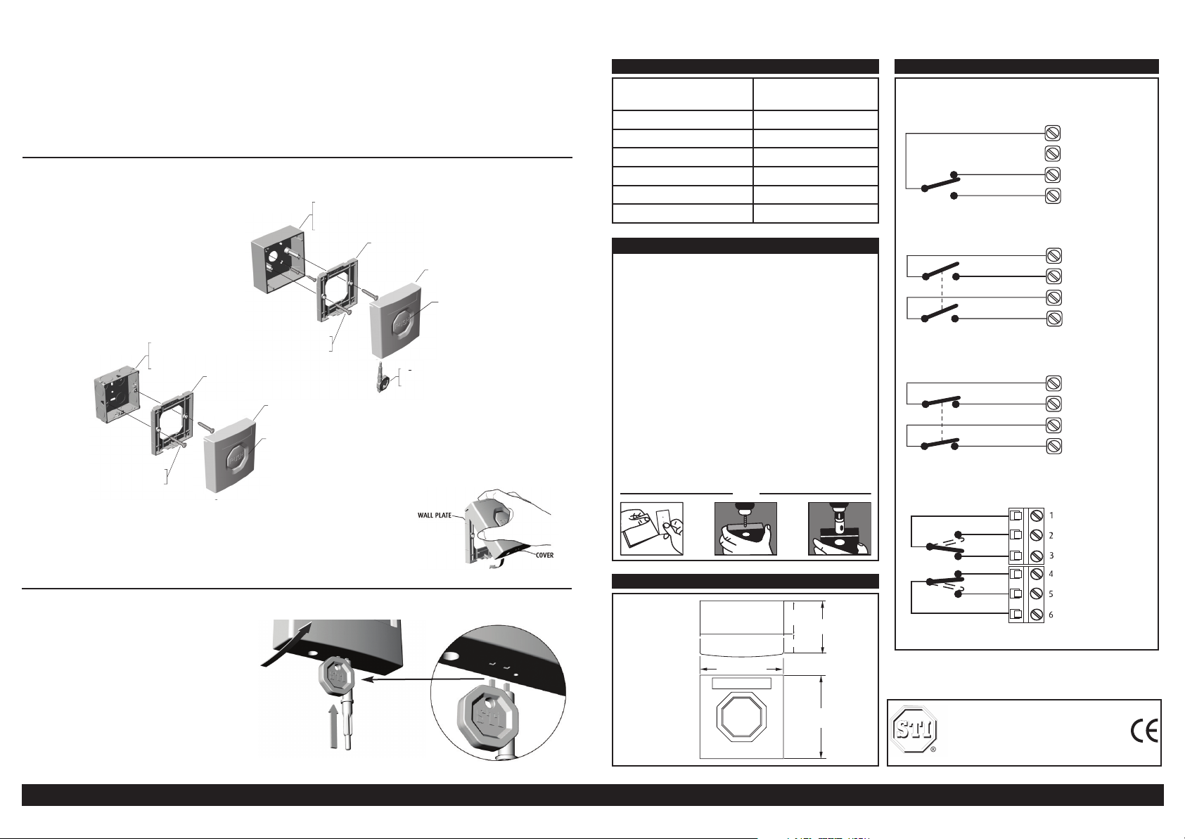
STANDARD FLUSH
MOUNTING
ELECTRICAL BOX
A
COVER
SCREW 3.5 X 35
(2) PROVIDED
PUSH BUTTON
(MOMENTARY)
STOPPERSWITCH
SURFACE BACK BOX
(OPTIONAL)
WALL PLATE
COVER
RESET KEY
(1) PROVIDED
SCREW 3.5 X 35
(2) PROVIDED
WALL PLATE
PUSH BUTTON (LATCHING)
Installation Data for the StopperSwitch SS3000 Series
A highly versatile range of attractive switches combining unique design, quality and value. Quick and easy to install, these
aesthetically appealing, low/high voltage switches fit any standard UK-type switch socket box.
· StopperPush models are for applications where a momentary push and release activation is desired.
· StopperLatch is ideal for applications where repeat activation must be controlled. Once the switch has been manually activated, it
can only be reset by inserting a special key.
All models are available in five colours with space for corporate branding, function marking and operating instructions.
A number of standard models are available for quick delivery but enquiries for custom models are welcomed.
SURFACE MOUNTING
FLUSH MOUNTING
NB: Carefully attach the StopperSwitch cover to the top
of the wall plate and hinge down to snap securely into
place. (As illustrated Dia. A.)
Dia. A
Specifications - Push Button Models
Current Carrying Capacity
(non switching)
Insulation Resistance >1250V
Electrical Contact Material Silver Plated Brass
Housing and Mounting Box Material Polycarbonate
Installation Terminal Conductor Size 0.5mm - 2.5mm
Operating Temperature -20°C to +65°C
Colours Red, Yellow, Green, Blue & White
6 Amps 12-24V DC
6 Amps 125-250V AC
Methods of Mounting
Flush installations
The StopperSwitch is provided with a wall plate that is
designed to fit directly onto a standard UK single 35mm deep
flush box.
Secure the wall plate to the flush mount box with the screws
provided. Carefully attach the StopperSwitch to the top of the
wall plate and hinge down to snap securely into place. (See
Dia. ‘A’ over).
Surface Installations
The Switch can be supplied complete with its own surface
mounting back box, 20mm entry holes can be easily cut using
the template provided on each pack box. (See ill. ‘B’ below).
With the screws provided, fix the back box to the wall and
secure the wall plate to the back box. Carefully attach the
StopperSwitch to the top of the wall plate and hinge down
to snap securely into place. (See Dia. ‘A’ over).
B
A
Dimensions
SS3000 Series
Single Pole Changeover
Denotes a StopperSwitch that is fitted with a single pole changeover
switch both the normally open and normally closed contacts are easily
accessed through the installer terminals as illustrated.
Double Pole Normally Open
Denotes a StopperSwitch that is fitted with a double pole normally
open switch easily accessed through the installer terminals as
illustrated.
Double Pole Normally Closed
Denotes a StopperSwitch that is fitted with a double pole normally
closed switch easily accessed through the installer terminals as
illustrated
Double Pole Changeover
Denotes a StopperSwitch that incorporates two independent single pole
changeover switches providing double pole changeover contacts.
Easily accessed through installer terminals as illustrated.
Detaching the cover from the wall plate
1. Insert key into the bottom of the StopperSwitch
cover.
2. Keep the key inserted and with your hand pull the
cover towards you. (As illustrated Dia. B)
Need help? Call our Technical Support Team on Freephone 0800 085 1678 (UK) Tel: 44 (0)1527 520999 (UK & Europe)
Dia. B
TOP VIEW
FRONT VIEW
87mm
35mm
23mm
58mm
87mm
NB: Switch arrangements shown with StopperSwitch in standby.
Safety Technology International (Europe) Limited
Unit 49G · Pipers Road · Park Farm Ind. Est. · Redditch
Worcestershire · B98 0HU · England
Tel: +44 (0) 1527 520 999 · Fax: +44 (0) 1527 501 999
E mail: info@sti-europe.com · Web Site: www.sti-europe.com
IDSS3_Series • Revised 0409-046 • Printed in England
 Loading...