

Page 1
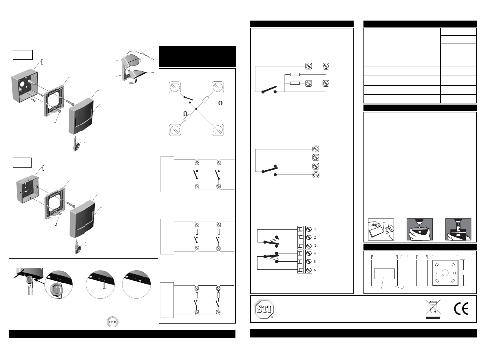
WALL
STANDARD FLUSH
MOUNTING
ELECTRICAL BOX
SCREW 3.5 x 35
(2) PROVIDED
A
RESET KEY
(1) PROVIDED
WALL PLATE
COVER
OPERATING ELEMENT
ReSet Call Point (RS) Series 01, 02 & 11
'ReSet' is a unique fire alarm manual call point that mimics the feel of breaking glass whilst offering the user the benefits and safety advantages
of a glass-free resettable operating element. Once activated a warning flag drops in to view easily identifying the call point that has been
operated. A key can then reset the unit. The 'ReSet' provides an ideal solution for most conventional fire alarm systems. It is ideal for industries
that are sensitive to broken glass as well as areas that suffer from a high number of false activations such as schools, shopping centres and
other public places.
ReSet Series 01 Configuration
Connection Options for
ReSet Call Point Series 01
1
1
4
4
control panel
Option 1 terminals 1 & 4
Normally open switch closing on alarm
680
3
1
680
1
3
control panel
470
2
1
470
1
2
control panel
Option 2 terminals 1 & 2
Normally open switch closing on alarm with a
470 ohm resistor fitted inseries with the switch
Option 3 terminals 1 & 3
Normally open switch closing on alarm with a
680 ohm resistor fitted inseries with the
switch
1
2
3
4
470
680
EN54-11
Cert. No. 653a/01
Series 01 ONLY
FLUSH
MOUNTING
RESET CALL POINT SURFACE MOUNTING
BACKBOX (COLOUR MATCHED)
(OPTIONAL)
RESET KEY
(1) PROVIDED
SCREW 3.5 x 35
(2) PROVIDED
WALL PLATE
COVER
OPERATING ELEMENT
SURFACE
MOUNTING
NB: Carefully attach the
ReSet call point to the
top of the wall plate
and hinge down to snap
securely into place.
(As illustrated Dia. A.)
WALL PLATE
COVER
Dia. A
1
2
Dia. B
Detaching the lid from the wall plate
1. Insert key into the bottom of the
ReSet lid.
2. Keep the key inserted and with your
hand pull the lid towards you. (As
illustrated Dia. B)
NB: For a surface mount installation, please
ensure that the security screw supplied with
this pack is fitted. (As illustrated Dia. C)
Dia . C (Only applies to EN54-11 Fire ReSet Series 01)
Need help? Call our Technical Support Team on Toll Free: 0800-888-4784
Technical Data for ReSet Call Point (RS) Series 01, 02 & 11
Series 01
Denotes a ReSet call point that will interface with most
conventional fire alarm systems. It is fitted with two internal
resistors 470 and 680 ohm. These are easily accessed through the
installer terminals as illustrated.
Series 02
Denotes a ReSet call point that is fitted with a single pole
changeover switch both the normally open and normally closed
contacts are easily accessed through the installer terminals as
illustrated.
Series 11
Denotes a ReSet call point that incorporates two independent
single pole changeover switches providing double pole changeover
contacts. Easily accessed through installer terminals as illustrated.
IDReSet-RS_Series01-02 &11 • Revised 01/12-014USA • Printed in England
Flush installations
The ReSet is provided with a wall plate that is designed to fit
directly onto a standard UK single 35mm deep flush box.
Secure the wall plate to the flush mount box with the screws
provided. Carefully attach the ReSet call point to the top of the
wall plate and hinge down to snap securely into place.
(See Dia. ‘A’ over).
Surface Installations (RS)
The ReSet can be supplied complete with its own surface
mounting back box, 20mm entry holes can be easily cut using
the template provided on each pack box. (See ill. ‘B’ below).
With the screws provided, fix the back box to the wall and
secure the wall plate to the back box. Carefully attach the
ReSet call point to the top of the wall plate and hinge down to
snap securely into place. (See Dia. ‘A’ over). For EN54-11 Fire
ReSet Series 01 ensure that the security screw is fitted. (See
Dia. ‘C’ over).
ReSet Series 01, 02 & 11
Methods of Mounting
12
3
4
R1
470 ohm
R2
680 ohm
1
2
3
4
Dimensions
B
NB: Switch arrangements shown with ReSet in standby.
Current Rating (All Series)
Current Rating (Series 02 & 11)
Low Current Rating* (All Series)
3 Amps 12 - 24V DC
3 Amps 125 - 250V AC
1 - 100 mA 5 - 12V DC
0.1 Amps 125 - 250V AC
Housing and Mounting Box Material Polycarbonate
Electrical Contact Material Silver plated brass
Operating Temperature -20°C to +65°C
Installation Terminal Conductor Size 0.5mm - 2.5mm
Humidity (no condensation)
Specifications are typical and given at 25°C
0 to 95%
Relative humidity
Specifications
*Gold contacts are especially suitable for low current and voltages.
Typically they are used in the range from 5v, 1 mA DC to 12v 100 mA DC
Safety Technology International, Inc.
2306 Airport Road · Waterford · Michigan · 48327-1209
Phone: 248-673-9898 · Fax: 248-673-1246
Toll Free: 0800-888-4784 · E mail: info@sti-usa.com · Web Site: www.sti-usa.com
Need help? Call our Technical Support Team on Toll Free: 0800-888-4784
A
87 mm 23 mm 35 mm 87 mm
OPERATING ELEMENT
COVER
87 mm
 Loading...