

Page 1
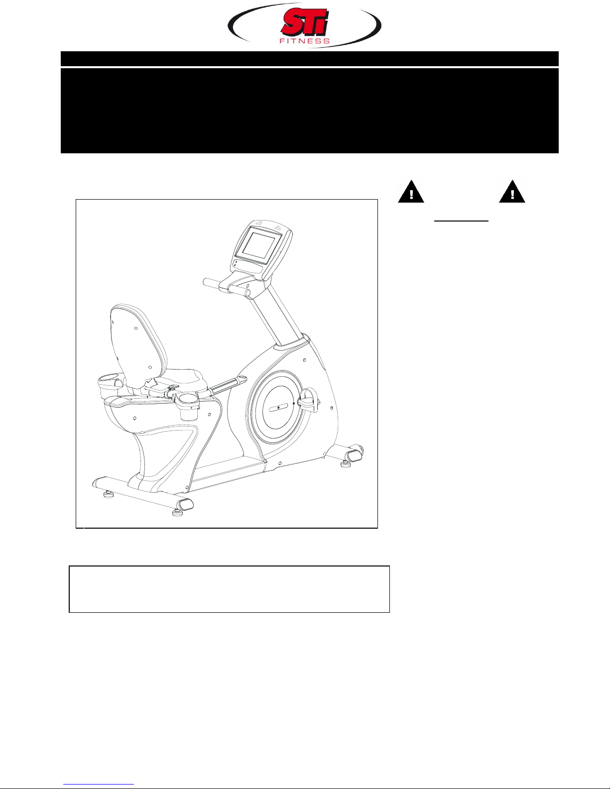
PR-8223
Product May Vary Slightly Different From Picture.
V. III
Exercise can present a
health risk. Consult a
physician before beginning
any exercise program with
this equipment.
If you feel faint or dizzy,
immediately discontinue use
of this equipment. Serious
bodily injury can occur if this
equipment is not assembled
and used correctly. Serious
bodily injury can also occur if
all instructions are not
followed.
Keep others and pets away
from equipment when in use.
Always make sure all bolts
and nuts are tightened prior
to each use. Follow all safety
instructions in this manual.
WARNING
CAUTION:
Weight on this product should not exceed 181 kgs/ 400 lbs
MADE IN TAIWAN
OWNER’S MANUAL
RECUMBENT BIKE
Page 2

1
SAFETY INSTRUCTIONS
WARNING: To reduce the risk of serious injury, read the following Safety Instructions before using the
Upright Bike.
1. Read all warnings posted on the Recumbent Bike.
2. Read this Owner's Manual and follow it carefully before using the Recumbent Bike. Make sure that it is
properly assembled and tightened before use.
3. We recommend that two people be available for assembly of this product.
4. Keep children away from the Recumbent Bike. Do not allow children to use or play on the Recumbent Bike.
Keep children and pets away from the Recumbent Bike when it is in use.
5. It is recommended that you place this exercise equipment on an equipment mat.
6. Set up and operate the Recumbent Bike on a solid level surface. Do not position the Recumbent Bike on
loose rugs or uneven surfaces.
7. Inspect the Recumbent Bike for worn or loose components prior to use.
8. Tighten/replace any loose or worn components prior to using the Recumbent Bike.
9. Consult a physician prior to commencing an exercise program. If, at any time during exercise, you feel faint,
dizzy, or experience pain, stop and consult your physician.
10. Follow your physician's recommendations in developing your own personal fitness program.
11. Always choose the workout which best fits your physical strength and flexibility level. Know your limits and train
within them. Always use common sense when exercising.
12. Before using this product, please consult your personal physician for a complete physical examination.
13. Do not wear loose or dangling clothing while using the Recumbent Bike.
14. Never exercise in bare feet or socks; always wear correct footwear, such as running, walking, or cross-training
shoes.
15. Be careful to maintain your balance while using, mounting, dismounting, or assembling the Recumbent Bike,
loss of balance may result in a fall and serious bodily injury.
16. Keep both feet firmly and securely on the Foot Pedals while exercising.
17. The Recumbent Bike should not be used by persons weighing over 400 pounds /181 kgs.
18. The Recumbent Bike should be used by only one person at a time.
19. Maintenance: Replace the defective components immediately and/or keep the equipment out of use until
repair the equipment completely.
20. The Recumbent Bike is well-suited to studio use (Class S.)
21. Make sure that adequate space is available for access to and passage around the Recumbent Bike; keep at
least a distance of 1 meter from any obstruction object while using the machine.
WARNING: Before starting any exercise or conditioning program you should consult with your personal physician
to see if you require a complete physical exam. This is especially important if you are over the age of 35, have
never exercised before, are pregnant, or suffer from any illness. READ AND FOLLOW THE SAFETY
PRECAUTIONS. FAILURE TO FOLLOW THESE INSTRUCTIONS CAN RESULT IN SERIOUS BODILY
Page 3
2
INJURY.
BEFORE YOU BEGIN
Thank you for choosing the self-powered Recumbent
Bike. We take great pride in producing this quality
product and hope it will provide many hours of quality
exercise to make you feel better, look better and enjoy
life to its fullest.
Yes, it's a proven fact that a regular exercise program
can improve your physical and mental health.
Too often, our busy lifestyles limit our time and
opportunity to exercise. The Recumbent Bike
provides a convenient and simple method to begin your
assault on getting your body in shape and achieving a
happier and healthier lifestyle.
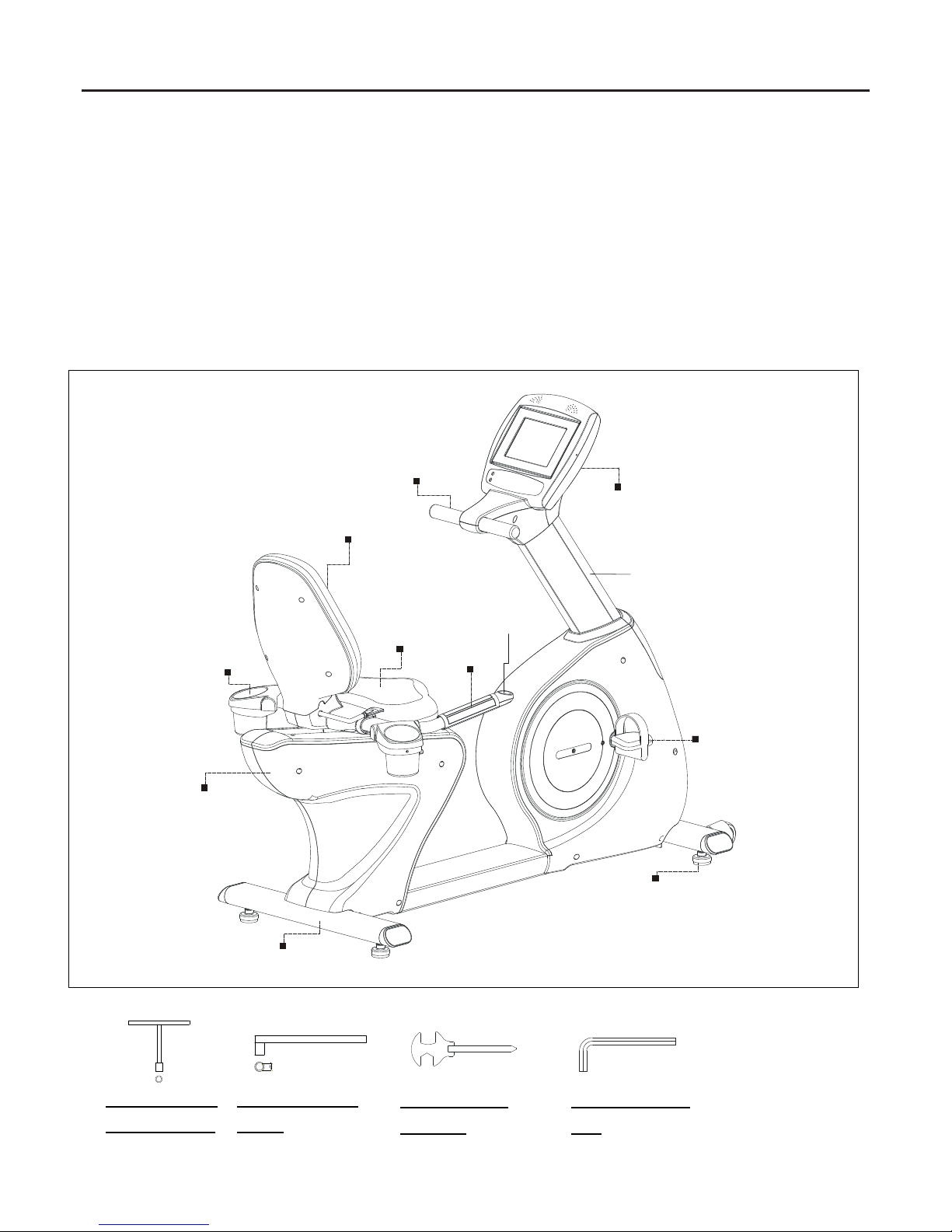
Before reading further, please review the drawing
below and familiarize yourself with the parts that are
labeled. Read this manual carefully before using the
Recumbent Bike.
THE FOLLOWING TOOLS ARE INCLUDED FOR ASSEMBLY:
Console
Pedal
Main Frame
Leveler
Rear Stabilizer
Accessory
Tray
Upright Post
Handlebar
Back
Cushion
Seat
Quick
Access
Key Base
Pulse
Sensor
T-HAND SOCKET
WRENCH (17mm)
SOCKET WRENCH
(13mm)
ALLEN WRENCH
(M6)
COMBINATION
WRENCH
Page 4
3
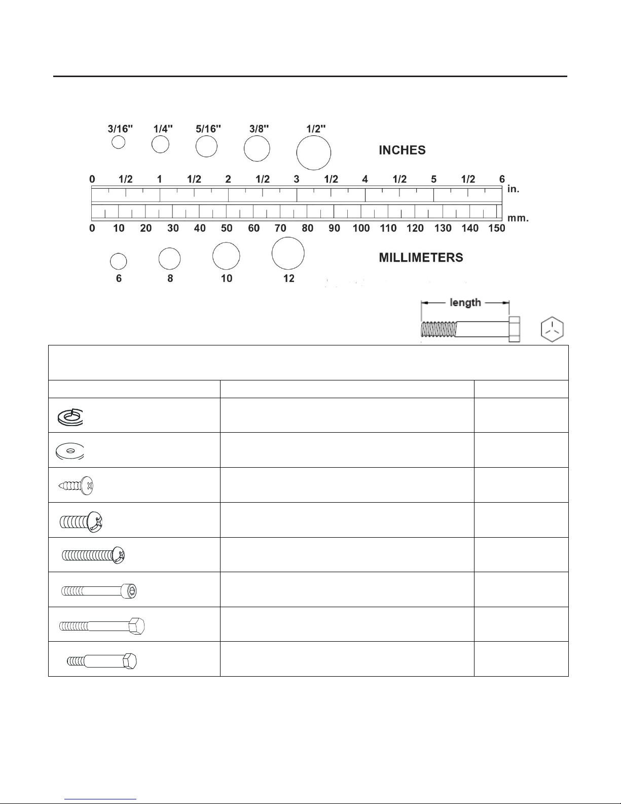
HARDWARE IDENTIFICATION CHART
This chart is provided to help identify the hardware used in the assembly process. Place the washers, the end of the bolts,
or screws on the circles to check for the correct diameter. Use the small scale to check the length of the bolts and screws.
NOTICE: The length of all bolts and screws except those with flat heads is
measured from below the head to the end of the bolt or screw. Flat head bolts and
screws are measured from the top of the head to the end of the bolt or screw.
After unpacking the unit, open the hardware bag and make sure that you have all the following items. Some hardware
may be already attached to the part.
Part No. and Description
Qty
86 Lock Washer (M8)
6
87 Washer (8x38x2.0t)
4
96 Screw (M4x10mm)
97 Screw (M4x20mm)
4
3
99 Bolt (M5xp0.8x15mm)
10 100 Bolt (M5xp0.8x30mm)
2 107 Bolt (M8xp1.25x55mm)
2
112 Bolt (M8xp1.25x65mm)
4
117 Bolt (M10xp1.5x50mm)
2
Page 5
4
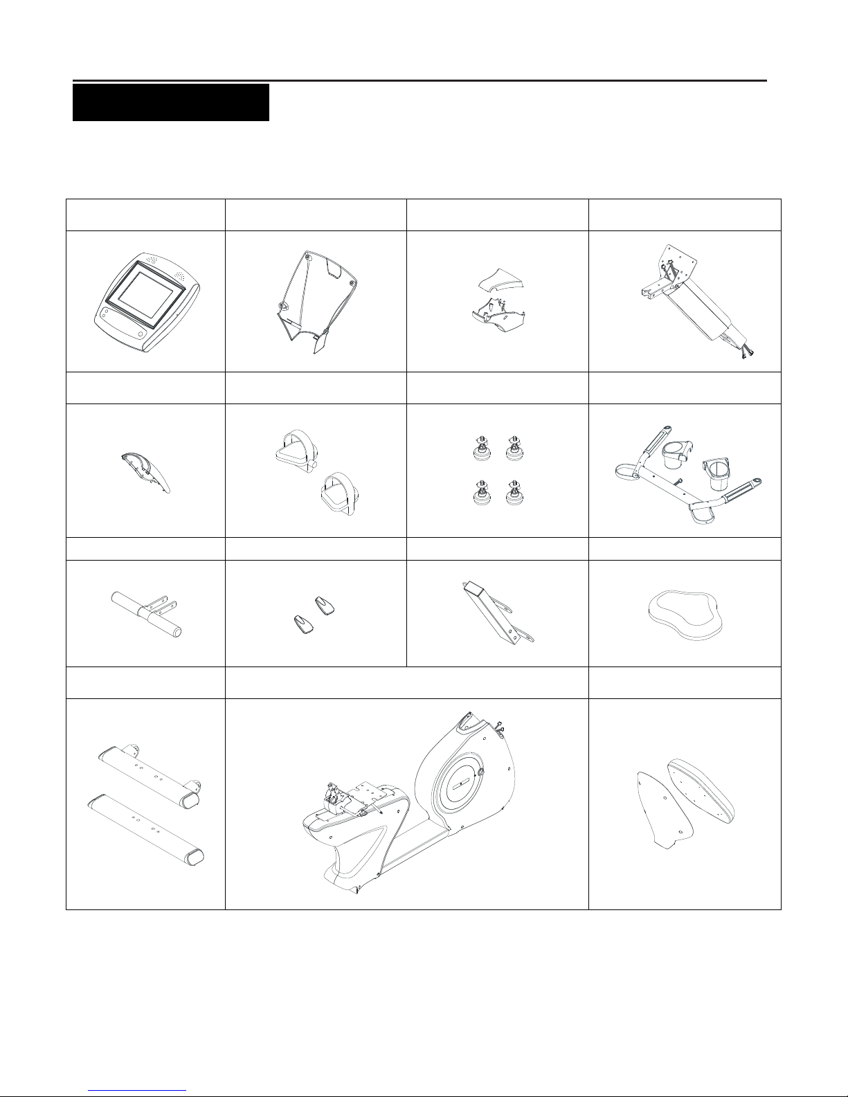
“ASSEMBLY PARTS”
Unpack the box in a clear area. Follow the List of Assembly Parts below to check and make sure all assembly parts are
present and in good condition. Do not dispose of the packing material until the assembly process is completed. Assembly
tools and hardware kit have included for you to use when assembling the product
Console
Console Bracket
Handlebar Decoration
Cover
Upright Post Assembly
Front Decoration Cover
Pedal
Leveler
Seat Handlebar Assembly &
Accessory Tray
Upper Handlebar
Adjustment Handle
Back Cushion Frame
Seat
Front and Rear
Stabilizer
Main Frame
Back Cushion & Back
Cushion Cover
Page 6
5
“ASSEMBLY INSTRUCTIONS”
Place all parts from the box in a cleared area and position them on the floor in front of you. Remove all packing
materials from your area and place them back into the box. Do not dispose of the packing materials until
assembly is completed. Read each step carefully before beginning.
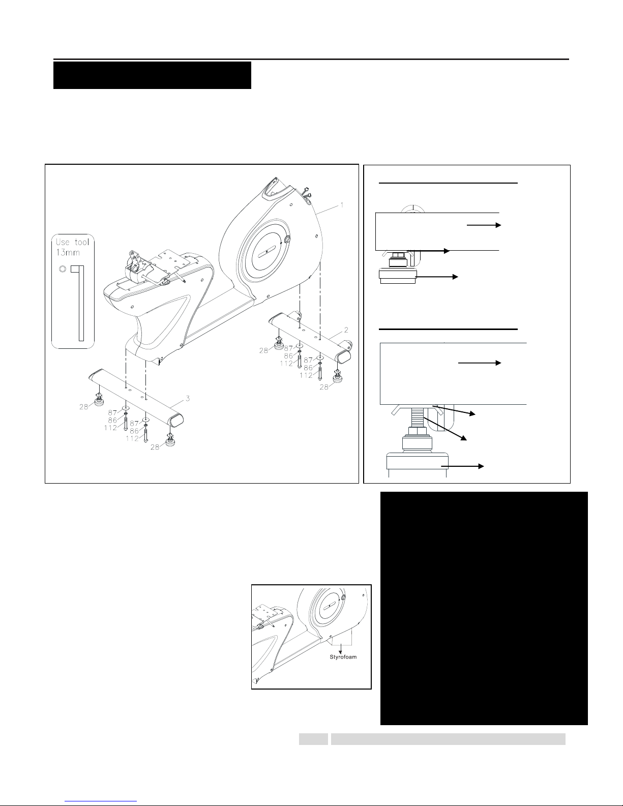
STEP 1 – Leveler Assembly
a. Attach 4pcs Levelers (28) to the Front Stabilizer (2) and the Rear
Stabilizer (3.)
b. Be sure to tighten the Levelers (28) securely against the Stabilizers
(2, 3) until screw lines are eliminated as the drawing 1 shown.
STEP 2 – Stabilizer Assembly
a. In order to assemble the Stabilizer (2, 3)
smoothly, it is suggested to place one
Styrofoam (or any stationary object)
under one side of the Main Frame (1)
that is going to assemble the stabilizer.
b. Attach the Front Stabilizer (2) and the
Rear Stabilizer (3) onto the Main Frame (1) and secure with the
Washers (8x38x2.0t)(87), the Lock Washers (M8)(86) and the Bolts
(M8xp1.25x65mm)(112) by using the socket wrench. NOTE: If the item is not level, review the LEVELING NOTE on
Detailed Lever- drawing 1
Detailed Lever- drawing 2
Adjustment Plate
Stabilizer
Leveler (28)
Screw line
Stabilizer
Adjustment Plate
Leveler (28)
LEVELING: After placing the bike
in the intended location for use,
check the stability of the bike. If the
bike is not level, reviewing the
following direction:
Loosen the Leveler (28) to make
the Adjustment Plate become less
tight.
Adjust the Leveler (28) for leveling.
Tighten the Adjustment Plate
securely against the Stabilizer to
lock the Leveler (28) in stable
position as the drawing 2 shown.
Page 7
6
the right side to level the Levelers (28).
“ASSEMBLY INSTRUCTIONS”
STEP 3 – Connection Wire Assembly
a. Plug the Middle Connection Wire (130) into the Lower Connection Wire (131). Be careful not to pinch the wires.
b. Plug the Pulse Sensor Wire 2 (134) into the Pulse Sensor Wire 3 (135). Be careful not to pinch the wires.
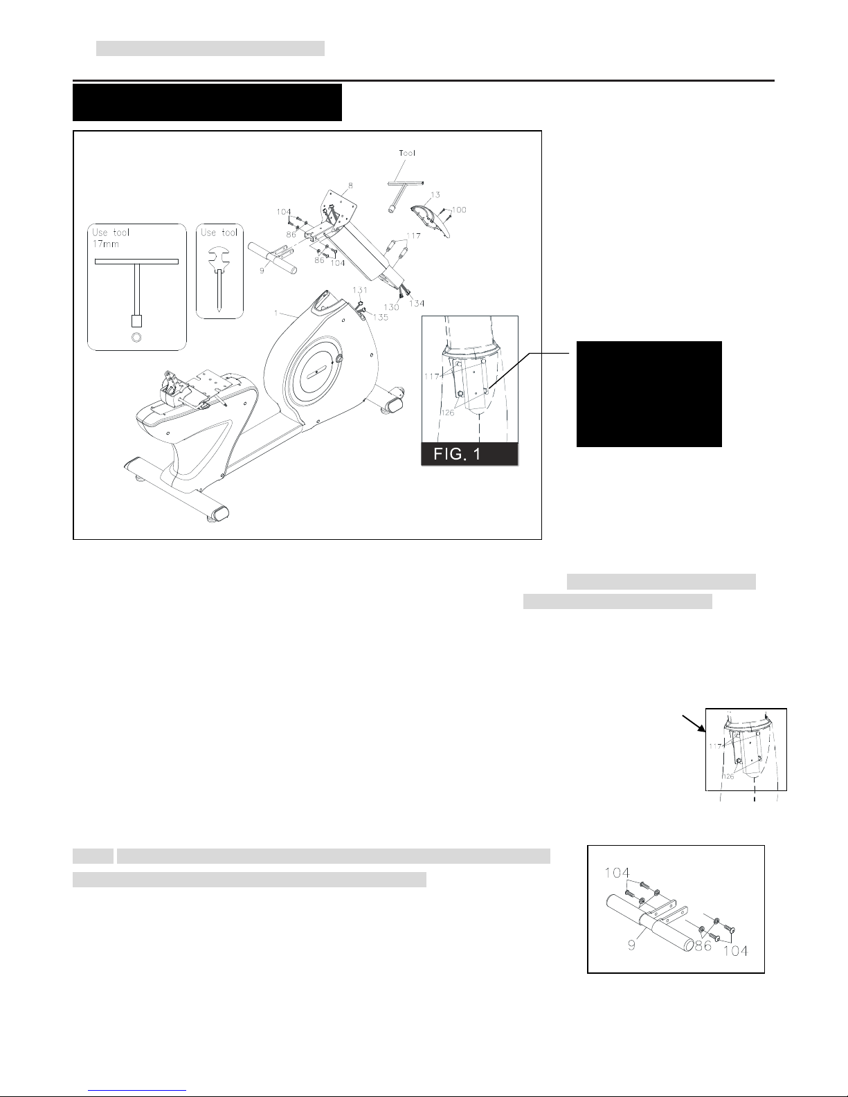
STEP 4 – Upright Post Assembly
a. Refer to FIG. 1, check that 2pcs Nylock Nuts (M10)(126) have pre-assembled into the front of the Main Frame (1)
(they will not be tight so that slotted bracket of the upright post will slide between the nut and the frame).
b. Insert the Upright Post (8) into the Main Frame (1) and secure with 2pcs Bolts (M10xp1.5x50mm)(117) by using the
T-HEAD SOCKET WRENCH as shown. Then fully tighten with 2pcs Nylock Nuts (M10)(126).
STEP 5 – Front Decoration Cover Assembly
Attach the Front Decorative Cover (13) onto the front of the Main Frame (1) with 2pcs Bolts (M5xp0.8x30mm)(100).
STEP 6 – Stationary Handlebar Assembly
NOTE: For shipping purpose, 4pcs Bolts (M8xp1.25x20mm)(104) and 4pcs Lock
Washers (86) are attached on the Stationary Handlebar (9).
a. Remove 4pcs Bolts (M8xp1.25x20mm)(104) and 4pcs Lock Washers (86) from
the Stationary Handlebar (9).
b. Insert the Stationary Handlebar (9) into the Upright Post (8) and secure with 4pcs
Bolts (M8xp1.25x20mm)(104) and 4pcs Lock Washers (86).
NOTE: Do not
remove the Nuts
(126) during
assembly
Page 8
7
“ASSEMBLY INSTRUCTIONS”
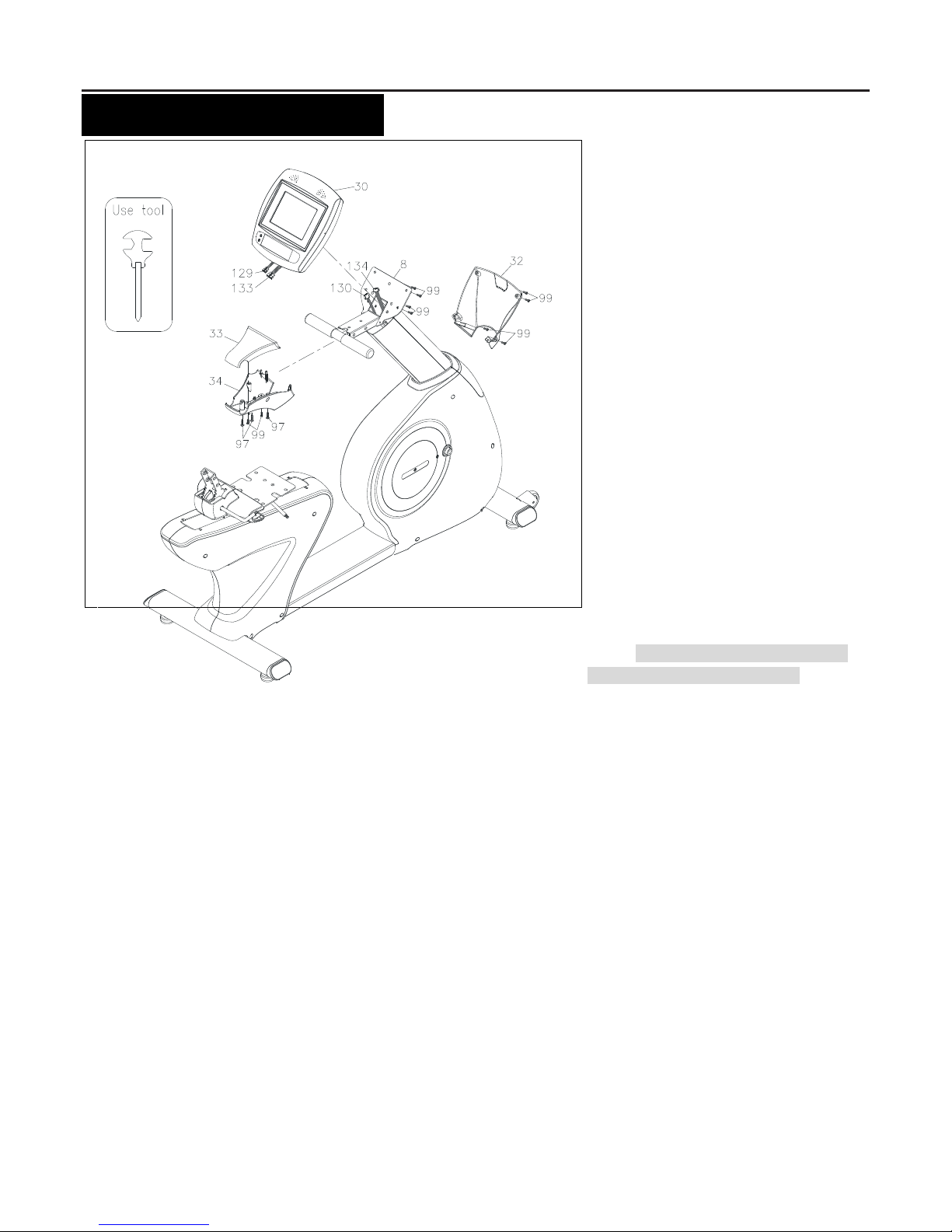
STEP 7 – Connection Wire and Console Assembly
a. Plug the Upper Connection Wire (129) into the Middle Connection Wire (130). Be careful not to pinch the wires.
b. Plug the Pulse Sensor Wire 1 (133) into the Pulse Sensor Wire 2 (134). Be careful not to pinch the wires.
c. Place the Console (30) onto the Upright Post (8) and secure with 4pcs Bolts (M5xp0.8x15mm)(99).
STEP 8 – Console Sleeve and Decoration Cover Assembly
a. Attach the Console Sleeve (33) to the Console (30) and secure with 4pcs Bolts (M5xp0.8x15mm)(99).
b. Attach the Upper Handlebar Decoration Cover (33) and the Lower Handlebar Decoration Cover (34) to the
Upright Post Assembly (8) and secure with 3pcs Screws (M4x20mm)(97) and 2pcs Bolts (M5xp0.8x15mm)(99).
Page 9
8
“ASSEMBLY INSTRUCTIONS”
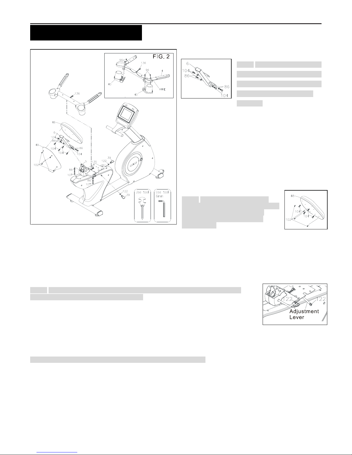
STEP 9 – Back Cushion Frame
Assembly
NOTE: For shipping purpose, 4 pcs
Lock Washers (M8)(86) and 4 pcs
Bolts (M8xp1.25x20mm)(104) are
attached on the Back Cushion
Frame (6).
a. Loosen 4 pcs Lock Washers (M8)(86) and 4 pcs
Bolts (M8xp1.25x20mm)(104) at both sides of the
Back Cushion Frame (6).
b. Follow the direction of the drawing line. Insert the
Back Cushion Frame (6) onto the Back Cushion
Adjustment Bracket (5) and secure with 4 pcs Lock
Washers (M8)(86) and 4 pcs Bolts
(M8xp1.25x20mm)(104).
STEP 10 – Back Cushion & Cover
Assembly
NOTE: For shipping purpose, 4 pcs
Bolts (M8xp1.25x20mm)(104) and 4pcs
Bolts (M6xp1.0x15mm)(102) are
attached on the back of the Back
Cushion (48).
a. Remove 4 pcs Bolts (M8xp1.25x20mm)(104) and 4pcs Bolts (M6xp1.0x15mm)(102) from the back
of the Back Cushion (48).
b. Attach the Back Cushion (48) onto the Back Cushion Frame (6) and secure with 4 pcs Bolts
(M8xp1.25x20mm)(104).
c. Then attach the Back Cushion Cover (49) onto the Back Cushion (48) and secure with 4pcs Bolts (M6×p1.0×15mm)
(102).
STEP 11 – Adjustment Lever Assembly
NOTE: For shipping purpose, each Adjustment Lever has pre-assembled one pcs Nut
(M8)(122) as the illustration shown on the right.
a. Attach each one Adjusting Handle (39) to two Adjustment Levers to the proper desired
position.
b. To fully secure the Adjusting Handle (39) by rotating the Nut (M8)(122) in
counterclockwise direction until completely reach to the Adjusting Handle (39).
STEP 12 – Accessory Tray Assembly
Refer to FIG.2. Turn the Seat Handlebar (4) to have the Hand Pulse Sensor Plate downward. Attach the Accessory
Tray (40) onto the Seat Handlebar (4) and secure with 4pcs Screws (M4x10mm)(96).
NOTE: Do not damage the Pulse Sensor Wire 4 (136) during Step 12.
STEP 13 – Seat Handlebar Assembly
Follow the direction of the drawing line. Place the Seat Handlebar (4) onto the Main Frame (1) and secure with 2pcs Lock
Washers (M8)(86) and 2pcs Bolts (M8xp1.25x55mm)(107).
STEP 14 – Pulse Sensor Wire Assembly
Connect the Pulse Sensor Wire 4 (136) to the Pulse Sensor Wire 3 (135).
Page 10

9
“ASSEMBLY INSTRUCTIONS”
STEP 15 – Seat Assembly
NOTE: For shipping purpose, 4 pcs Bolts (M8xp1.25x20mm)(141) are attached at the bottom of the Seat (46).
a. Loosen 4pcs Bolts (M8xp1.25x20mm)(141) at the bottom of the Seat (46).
b. Attach the Seat (46) onto the Seat Frame (7) and secure with 4pcs Bolts (M8xp1.25x20mm)(104).
STEP 15 – Pedal Assembly
Tread the Right Pedal (16) clockwise into the Right Crank located inside the Right Crank Cover. Tighten the pedal
securely. Repeat the same procedure to thread and tighten the Left Pedal (15) counter-clockwise into the Left Crank.
For the final step, make sure all the bolts and nuts are tighten securely before using the item.
Page 11

10
“OPERATIONAL INSTRUCTIONS”
HOW TO ADJUST CONSOLE ANGLE
To get the best console angle, it’s suggested to use both hands to hold the upper and
lower end of the console (area A or B) and gently adjust the console angle to the proper
position
HOW TO TOW THE ITEM SAFELY
Hold the Rear Stabilizer (3) up with two hands and tow the item to
the desired place carefully
Make sure the floor is level while towing the item
BACK CUSHION ADJUSTMENT
To adjust the most suitable angle, pull the Back
Cushion Adjustment Bar upward while lying on the
cushion.
Release the Back Cushion Adjustment Bar and
hear the “click” sound to secure the desired angle of
the back cushion.
SEAT ADJUSTMENT
To adjust the most suitable position, pull the Seat
Adjustment Bar upward to move the seat forward
and backward.
Once adjusting to the most suitable position, release the Seat Adjustment Bar until hearing “click” sound.
Back Cushion
Seat Adjustment Bar
Seat
Back Cushion
Adjustment Bar
Page 12

11
“CONSOLE OVERVIEW & CONSOLE BUTTON”
Console Buttons:
Button Name
Function Description
START
Press START to begin/continue your exercise.
PAUSE
Press PAUSE to pause all functions during your exercise program. All the data on the display
will pause except for PULSE readout
STOP
Press STOP to stop current profile, all the date will reset to its original setting value except for
PULSE readout
UP
Press UP to increase the level of tension during exercise
DOWN
Press DOWN to decrease the level of tension during exercise
BACK
Press BACK to return to previous page
Speaker
Speaker
MP3/CD
player Jack
Mute
Button
Headphone
Jack
The console display may vary slightly from the actual console display, the above console
overview is for reference only
Page 13

12
“CONSOLE INSTRUCTIONS – CONSOLE BUTTON”
Console Buttons:
H.R. Trend:
Press H.R. Trend to review your heart rate
chart.
The Heart Rate Trend is recorded
automatically in every 60 seconds if the
user’s actual heart rate is able to detect by
the console.
NOTE: Please be sure to wear a chest belt
or place both of hands on the Pulse
Sensors located on the Handlebar in order
to make sure that the pulse readout could
be able to detect.
Press H.R. Trend again to return to the workout program.
STATISTICS:
Press STATISTICS to review your workout statistics. NOTE: The button is able to press at
anytime to review the workout statistics during exercise.
“CONSOLE INSTRUCTIONS – CONSOLE FUNCTION”
Console Functions:
PULSE:
Wear chest belt or place both of hands on the Pulse Sensors located on the
Handlebar. The pulse will be displayed within several seconds after the heart symbol
“ ” is displayed.
If the hands are not correctly positioned on the sensors, and a few seconds passes
without a pulse input, the console will turn off the pulse circuit. Replace hands back on
the Pulse Sensors correctly, and the pulse readout will appear again.
WATT:
Display range: 0 ~ 999 Watt.
Page 14

13
“CONSOLE INSTRUCTIONS – CONSOLE FUNCTION”
LEVEL: For this TFT console, the LEVEL HAS TWO MEANINGS, SINCERELY PLEASE TAKE
A LOOK BELOW,
For Manual, Constant Power Program, Level means “resistance/tension level”; Display
range: 1 ~ 20 resistance levels.
For FITNESS, RANDOM, ROLLING, FAT BURN, ASCENT, IRON MAN, MOUNTAIN,
WEIGHT LOSS, INTERVAL, VALLEY, Level means “Workout Difficulty Level”; Display
range: 1 ~ 20 workout difficulty levels. For example, The level of 20’s Watt range would be
heavier than the level of 8’s Watt range. The lower level of workout difficulty you select, the
workout difficulty Watt range would decrease, making more easier for user to exercise.
SPEED:
Display range: 0.0~99.9 km/h.
TIME:
Count Up: If a target time is not selected, TIME will count up from 0:00 to maximum 99:59
minutes.
Count Down: If a target time is set, (5:00 TO 99:00; 1 MINUTE INCREMENTS), the console
will count down from that selected target time to 0:00.
DISTANCE:
Display range: 0.0~99.9 km/h.
RPM:
Display range: 0~255.
CALORIES:
Display range: 0~9999.
METS:
Definition: MET or metabolic equivalent is a term commonly used to measure or express an
average person’s metabolic rate, is the amount of oxygen used by an average seated person. One
MET is the amount of energy or oxygen used to sit quietly for a minute.
1 MET= 3.5ml/kg/min (the body consumes 3.5 milliliters of oxygen a minute for each kilogram of
body weight), is the energy (oxygen) used by the body at rest, while sitting quietly or reading a
book, for example.
The harder your body works during the activity, the more oxygen is consumed and the higher the
MET level. If you are exercising at a level of 7 METS, this means that you are working about 7
times as hard as you would be at rest. You are consuming about 7 times the amount of oxygen as
you would at rest as well.
Activity that burns 3 to 6 METs is considered moderate-intensity physical activity.
Activity that burns > 6 METs is considered vigorous-intensity physical activity.
Page 15

14
“CONSOLE OPERATION”
Power ON:
Pedaling over 25rpm to power on the console. The console will display the stand-by screen as below.
Power Off:
The console would automatically shut off after 60 seconds of inactivity.
Boot Screen:
Stand-by screen displays 3 seconds later will then enter into the Boot Screen as below:
On Boot Screen, there are 3 main workout options.
1. Quick Start: Starting exercise directly in Manual Program without any setting.
2. Profile: including Basic profile and Advanced profile.
3. Heart Rate Control (60%, 65%, 70%, 75%, 80% and 85%)
NOTE:
► The console would shut down any time if rechargeable batteries are run out of power.
► If pedaling over 35rpm, the item will start charging batteries.
Boot Screen
Page 16

15
“CONSOLE OPERATION – QUICK START”
Quick Start:
1. Press “Quick Start” on Boot Screen.
After selecting Quick Start, following countdown pages will display sequentially.
►The countdown pages will appear before every entry of final main page.
2. Enter into final main page as below.
Press START to start workout
Press DOWN to decrease the
level of tension during exercise
Press UP to increase the level
of tension during exercise
Press STATISTICS to review your
average value of workout statistics
Press PAUSE to pause all functions during
your exercise program. All the data on the
display will pause except for PULSE
readout
Press STOP to stop current
profile, all the date will reset to its
original setting value except for
PULSE readout
Press BACK to return to
previous page
Press H.R.
Trend to
review your
heart rate
chart during
exercise.
Page 17

16
“CONSOLE OPERATION – PROFILE”
Profile:
1. Press “Profile” on Boot Screen.
2. Enter into Main Profile Selecting page.
Main Profile Selecting
There are 2 workout profiles for options.
■ Basic Profile: 6 different workout programs are available under Basic Profile.
■ Advanced Profile: 6 different workout programs are available under Advanced Profile.
LEVEL: For this TFT console, the LEVEL HAS TWO MEANINGS, SINCERELY PLEASE TAKE A LOOK BELOW,
For Manual, Constant Power Program, Level means “resistance/tension level”; Display range: 1 ~ 20
resistance levels.
For FITNESS, RANDOM, ROLLING, FAT BURN, ASCENT, IRON MAN, MOUNTAIN, WEIGHT LOSS, INTERVAL,
VALLEY, Level means “Workout Difficulty Level”; Display range: 1 ~ 20 workout difficulty levels. For example,
The level of 20’s Watt range would be heavier than the level of 8’s Watt range. The lower level of workout difficulty
you select, the workout difficulty Watt range would decrease, making more easier for user to exercise.
Page 18

17
“CONSOLE OPERATION –BASIC PROFILE”
“A” Basic Profile Instruction:
1. Press “Basic Profile”.
2. Enter into diagrams’ selection page.
Options include Manual, Fitness, Random, Rolling, Fat Burn, Ascent, total in 6 diagrams. Press the desired diagram
to workout.
3. Enter into Weight page and input the value of weight; display range: 30 ~ 181 kgs.
NOTE: When enter into
Random profile, the
workout profile will
randomly create each
time
Press BACK to return to
previous page.
Press QUICK START to start
exercise immediately.
Press NEXT to enter into Weight
Page for setting your weight.
Press BACK to return to
previous page.
Press QUICK START to
start exercise immediately.
Press NEXT to enter into TIME
Page for setting the desired time.
NOTE: Display range
from 30~181kgs
Page 19

18
“CONSOLE OPERATION –BASIC PROFILE”
4. Enter into Time page and select the desired value of time; display range: 5:00 ~ 99:00.
“B” Instruction Note for During Exercise:
H.R. Trend:
Press H.R. Trend to review your heart rate chart.
The Heart Rate Trend is recorded automatically in
every 60 seconds if the user’s actual heart rate is
able to be detected by the console.
NOTE: Please be sure to wear a chest belt or
place both of hands on the Pulse Sensors
located on the Handlebar in order to make sure
that the pulse readout could be able to detect.
Press H.R. Trend again to return to the workout program.
STATISTICS:
Press STATISTICS to review your average value of workout statistics. NOTE: The button is
able to press at anytime to review during exercise. Press Back to return to the workout
program.
Press BACK to return to
previous page.
Press QUICK START to
start exercise immediately.
Press NEXT to
start exercise.
NOTE: Display range
from 5:00 ~ 99:00
Page 20

19
“CONSOLE OPERATION – ADVANCED PROFILE”
“A” Advanced Profile Instruction:
1. Press “Advanced Profile”.
2. Enter into diagrams’ selection page.
Options include Constant Power, Iron Man, Mountain, Weight Lose, Interval, Valley, total in 6 diagrams. Press the
desired diagram to workout
Before operating CONSTANT POWER PROGRAM, review the difference between the CONSTANT POWER and the
CONSTANT RESISTANCE function:
Level Control (Constant
Resistance) in most of workout
programs
Watt Control (Constant Power) in Constant Power program
“RPM RESISTANCE --
Resistance does not change even
though the quantity of RPMs
(Rotate Per Minute) increases or
decreases under the Level
Control Mode during workout.
No matter how fast you pedal, the
resistance is fixed.
The resistance depends on the value of RPM (Rotate Per Minute.)
“RPM RESISTANCE ; RPM RESISTANCE ”
In order to remain at a consistent effort level (watts) (once you set up the
desired Watt value), the computer will start monitoring the user’s pedaling
speed/RPM.
If the RPMs (Rotate Per Minute) increase (when you pedal faster), the
Resistance will decrease (becomes lighter.)
On the contrary, the Resistance increases (becomes heavier resistance) when
the value of the RPMs decreases (when you pedal slower.)
Constant Power:
program of Watt Control;
Watts display range: 30
~350 watt
Page 21

20
“CONSOLE OPERATION – ADVANCED PROFILE”
3. Enter into Weight page and input the value of weight; display range: 30 ~ 181 kgs.
4. Enter into Time page and select the desired value of time; display range: 5:00 ~ 99:00
“B” Instruction Note for During Exercise:
H.R. Trend:
Press H.R. Trend to review your heart rate chart.
The Heart Rate Trend is recorded automatically in
every 60 seconds if the user’s actual heart rate is
able to be detected by the console.
NOTE: Please be sure to wear a chest belt or
place both of hands on the Pulse Sensors
located on the Handlebar in order to make sure
that the pulse readout could be able to detect.
Press H.R. Trend again to return to the workout program.
Press BACK to return to
previous page
Press QUICK START to
start exercise immediately
Press NEXT to enter into TIME
Page for setting the desired time
NOTE: Display range
from 30~181kgs
Press BACK to return to
previous page.
Press QUICK START to
start exercise immediately.
Press NEXT to
start exercise.
NOTE: Display range
from 5:00 ~ 99:00
Page 22

21
STATISTICS:
Press STATISTICS to review your average value of workout statistics. NOTE: The button is
able to press at anytime to review during exercise. Press Back to return to the workout
program.
“CONSOLE OPERATION – HEART RATE CONTROL PROFILE”
“A” Heart Rate Control Instruction:
1. Press Heart Rate Control on Boot Screen.
2. Enter into Weight page and input the value of weight; display range: 30 ~ 181 kgs.
Press BACK to return to
previous page.
Press QUICK START to
start exercise immediately.
Press NEXT to enter into TIME Page
for setting the desired time.
NOTE: Display range
from 30~181kgs
Page 23

22
“CONSOLE OPERATION – HEART RATE CONTROL PROFILE”
3. Enter into Time page and select the desired value of time; display range: 5:00 ~ 99:00
4. Enter into Age page and input the value of your age; display range: 5 ~ 99 years old.
5. Enter into Gender page and select your gender.
Press BACK to return to
previous page.
Press QUICK START to
start exercise immediately.
Press NEXT to
select your age.
NOTE: Display range
from 5:00 ~ 99:00
Press BACK to return to
previous page.
Press QUICK START to
start exercise immediately.
Press NEXT to select
your gender.
NOTE: Display range from 5 ~
99 years old ; Although the
console allows input for age
beginning at 5 years old, this
product is not recommended
for children usage
Press BACK to return
to previous page.
Press NEXT to select target heart rate.
Press QUICK START to
start exercise immediately.
Page 24

23
“CONSOLE OPERATION – HEART RATE CONTROL PROFILE”
6. Select your ideal target heart rate (60%, 65%, 70%, 75%, 80% and 85%).
NOTE for H.R.C. Program:
60%, 65%, 70%, 75%, 80% and 85% of max. heart rate:
Male formula: heart rate percentage % of (220 – your age)
Female formula: heart rate percentage % of (225 – your age)
“B” Instruction Note for During Exercise:
H.R. Trend:
Press H.R. Trend to review your heart rate chart.
The Heart Rate Trend is recorded automatically in
every 60 seconds if the user’s actual heart rate is
able to be detected by the console.
NOTE: Please be sure to wear a chest belt or
place both of hands on the Pulse Sensors
located on the Handlebar in order to make sure
that the pulse readout could be able to detect.
Press H.R. Trend again to return to the workout program.
STATISTICS:
Press STATISTICS to review your average value of workout statistics. NOTE: The button is
able to press at anytime to review during exercise. Press Back to return to the workout
program.
Press BACK to return to
previous page.
Press QUICK START to
start exercise immediately
Press NEXT to start
exercise.
Page 25

24
“CONDITIONING GUIDELINES”
How you begin your exercise program depends on your physical condition. If you have been inactive for several
years, or are severely overweight, you must slowly and increase your time on the 2 in 1 Elliptical / Stepper
gradually: a few minutes per workout.
Initially, you may be able to exercise only for a few minutes in your target zone, however, your aerobic fitness
will improve over the next six to eight weeks. Don’t be discouraged if it takes longer. It’s important to work at
your own pace. Ultimately, you’ll be able to exercise continuously for 30 minutes. The better your aerobic fitness,
the harder you will have to work to stay in your target zone. Please remember these essentials:
˙ Have your doctor review your training and diet programs to advise you of a workout routine you should adopt.
˙ Begin your training program slowly with realistic goals that have been set by you and your doctor.
˙ Monitor your pulse frequently. Establish your target heart rate base on your age and condition.
˙ Set up your 2 in 1 Elliptical / Stepper a flat, even surface at least 3 feet from walls and furniture.
EXERCISE INTENSITY
To maximize the benefits of exercising, it is important to exercise with the proper intensity. The proper intensity
level can be found by using your heart rate as a guide. For effective aerobic exercise, your heart rate should be
maintained at a level between 70% and 85% of your maximum heart rate as you exercise. This is known as
your target zone. You can find your target zone in the table below. Target zones are listed for both
unconditioned and conditioned persons according to age.
During the first few months of your exercise
program, keep your heart rate near the low end
of your target zone as you exercise. After a few
months, your heart rate can be increased
gradually until it is near the middle of your target
zone as you exercise.
To measure your
heart rate manually,
stop exercising but
continue moving
your legs or walking
around and place
two fingers on your wrist. Take a six-second
heartbeat count and multiply the results by 10 to
find your heart rate. For example, if your
six-second heartbeat count is 14, your heart
rate is 140 beats per minute. (A six-second count is used because your heart rate will drop rapidly when you
stop exercising.) Adjust the intensity of your exercise until your heart rate is at the proper level.
Age
Target Heart Rate Zone
(55% ~ 90% of Max.
Heart Rate)
Average Max. Heart
Rate 100%
20
110-180 beats per minute
200 beats per minute
25
107-175 beats per minute
195 beats per minute
30
105-171 beats per minute
190 beats per minute
35
102-166 beats per minute
185 beats per minute
40
99-162 beats per minute
180 beats per minute
45
97-157 beats per minute
175 beats per minute
50
94-153 beats per minute
170 beats per minute
55
91-148 beats per minute
165 beats per minute
60
88-144 beats per minute
160 beats per minute
65
85-139 beats per minute
155 beats per minute
70
83-135 beats per minute
150 beats per minute
Page 26

25
“WARM-UP AND COOL-DOWN”
Warm-up The purpose of warming up is to prepare your body for exercise and to minimize injuries. Warm up for
two to five minutes before strength-training or aerobic exercising. Perform activities that raise your heart rate
and warm the working muscles. Activities may include brisk walking, jogging, jumping jacks, jump rope, and
running in place.
Stretching Stretching while your muscles are warm after a proper warm-up and again after your strength or
aerobic training session is very important. Muscles stretch more easily at these times because of their elevated
temperature, which greatly reduces the risk of injury. Stretches should be held for 15 to 30 seconds. Do not
bounce.
Suggested Stretching Exercises
Lower Body Stretch
Place feet shoulder-width
apart and lean forward. Keep
this position for 30 seconds
using the body as a natural
weight to stretch the backs of
the legs.
DO NOT BOUNCE!
When the pull on the back of
the legs lessen, try a lower
position gradually.
h
Floor Stretch
While sitting on the floor, open
the legs as wide as possible.
Stretch the upper body toward
the knee on the right leg by
using your arms to pull your
chest to your thighs. Hold this
stretch 10 to 30 seconds.
DO NOT BOUNCE!
Do this stretch 10 times.
Repeat the stretch with the left
leg.
Bent Torso Pulls
While sitting on the floor,
have legs apart one leg
straight and one knee bent.
Pull the chest down to touch
the thigh on the leg that is
bent and twist at the waist.
Hold this position at least 10
seconds. Repeat 10 times
on each side.
Bent Over Leg Stretch
Stand with feet shoulder-width
apart and lean forward as
illustrated. Using the arms,
gently pull the upper body
towards the right leg. Let the
head hand down. DO NOT
BOUNCE! Hold the position a
minimum of 10 seconds.
Repeat pulling the upper body
to the left leg. Do this stretch
several times slowly.
Remember always to check with your physician before starting any exercise program.
Cool-Down The purpose of cooling down is to return the body to its normal, or near normal, resting state at the end of
each exercise session. A proper cool-down lowers your heart rate and allows blood to return to the heart. Your cool-down
should include the stretches listed above and should be completed after each strength-training session.
Page 27

26
PARTS LIST
NO.
PARTS NAME
Q'TY
1
Main Frame
1
2
Front Stabilizer
1
3
Rear Stabilizer
1
4
Seat Handlebar
1 5 Back Cushion Adjustment Bracket
1 6 Back Cushion Frame
1
7
Seat Frame
1
8
Upright Post
1
9
Upper Handlebar
1
10
Front Left-Side Cover
1
11
Front Right-Side Cover
1
12
Upper Chain Cover
1
13
Front Decoration Cover
1
14
Crank Cover
2
15
Left Pedal
1
16
Right Pedal
1
17
Base Cover
1
18
Rear Left-Side Cover
1
19
Rear Right-Side Cover
1
20
Belt (1059mm J8)
1
21
Pulley (235mm)
1
22
Magnet
1
23
Pulley (120mm)
1
24
Belt (584mm J8)
1
25
Seat Rail EndCap
2
26
Sliding Belt
2
27
EndCap
4
28
Leveler (ψ50)
4
29
Transportation Wheel
2
30
Console
1
31
Battery Door
1
32
Console Bracket
1
33
Upper Handlebar Decoration Cover
1
34
Lower Handlebar Decoration Cover
1
35
Foam Grip
2
36
Plastic Seat Support Cover (L)
1
37
Plastic Seat Support Cover (R)
1
38
Back Cushion Hinge
1
NO.
PARTS NAME
Q'TY
39
Adjustment Handle
2
40
Accessory Tray
2
41
Quick-
1
42
Quick-Access Key Base (-)
1
43
Pulse Sensor Top Housing
2
44
Pulse Sensor Bottom Housing
2
45
Seat Roller
3
46
Seat
1
47
Square Plug (30x60mm)
1
48
Back Cushion
1
49
Back Cushion Cover
1
50
Front Aluminum Upright Cover
1
51
Rear Aluminum Upright Cover
1
52
Left Mounting Plate
1
53
Right Mounting Plate
1
54
Generator
1
55
Resistor
1
56
Controller
1
57
Crank Axle
1
58
Left Crank
1
59
Right Crank
1
60
Axle
1
61
One Way Bearing (2520mm)
1
62
One Way Pulley (51mm)
1
63
Idler Arm
1
64
Axle Cover
1
65
Idler Shaft
1
66
Idler Spring
1
67
Roller Plate
2
68
Roller Axle
1
69
Seat Adjustment Lever
1
70
Seat Torsion Spring
1
71
Back Cushion Adjustment Bracket
1
72
Cushion Linkage Axel
1
73
Cushion Torsion Spring
1
74
Cushion Spring
1
75
Cushion Adjustment Lever
1
Page 28

27
NO.
PARTS NAME
Q'TY
76
Bearing (6000N)
6
77
Bearing (6004zz)
8
78
Eye Bolt (40mm)
2
79
Eye Bolt (50mm)
4
80
Tension Bracket
2
81
Square Key (6×6×15mm)
1
82
Spacer (M8×12×7mm)
2
83
Seat Linkage Spacer
1
84
E Ring
2
85
C Ring
2
86
Lock Washer (M8)
20
87
Washer (8×38×2.0t)
6
88
Washer (10×23×2.0t)
2
89
Washer (10.6x60x2.0t)
1
90
Washer (17×25×1.0t)
1
91
Washer (18.3×25×1.0t)
1
93
Washer (21x30x1.0t)
2
94
Screw (M3×10mm)
3
95
Screw (M3×25mm)
4
96
Screw (M4x10mm)
4
97
Screw (M4x20mm)
15
98
Screw (M5x18mm)
23
99
Bolt (M5×p0.8×15mm)
14
100
Bolt (M5×p0.8×30mm)
2
101
Bolt (M5×p0.8×75mm)
2
102
Bolt (M6×p1.0×15mm)
4
103
Bolt (M5×p0.8×12mm)
6
104
Bolt (M8×p1.25×20mm)
16
105
Bolt (M10×p1.5×45mm)
1
106
Bolt (M6×p1.0×20mm)
4
107
Bolt (M8×p1.25×50mm)
4
108
Bolt (M10×p1.5×30mm)
1
109
Thin Bolt (M8×p1.25×15mm)
4
110
Bolt (M8×p1.25×15mm)
1
111
Bolt (M8×p1.25×60mm)
1
112
Bolt (M8×p1.25×65mm)
4
113
Bolt (M8×p1.25×75mm)
1
NO.
PARTS NAME
Q'TY
114
Bolt (M8×p1.25×80mm)
4
115
Bolt (M10×p1.5×145mm)
2
116
Bolt (M10×p1.5×144mm)
2
117
Bolt (M10×p1.5×50mm)
2
118
Bolt (M8×p1.25×12mm)
1
119
Bolt (M6×p1.0×12mm)
1
120
Bolt (L=35mm)
121
Nut (M6xp1.0)
3
122
Nut (M8xp1.25)
4
123
Nylon Nut (M6xp1.0)
4
124
Thin Nylon Nut (M8xp1.25)
4
125
Nylon Nut (M8)
12
126
Nylon Nut (M10)
6
127
Flange Nut (M10)
1
128
Nut (M10xp1.25)
1
129
Upper Connection Wire
1
130
Middle Connection Wire
1
131
Lower Connection Wire
1
132
Sensor Wire
1
133
Pulse Sensor Wire 1
1
134
Pulse Sensor Wire 2
1
135
Pulse Sensor Wire 3
1
136
Pulse Sensor Wire 4
1
137
Generator Wire
2
138
Battery Connection Wire
1
139
Battery
1
140
Battery Fixed Bracket
2
141
Bolt (M8xp1.25x20mm)
4
142
ψ20 Spacer (4.6mm)
1
143
ψ20 Spacer (36mm)
1
Page 29

28
PRODUCT PARTS DRAWING
 Loading...