

Product May Vary Slightly From Picture.
v. VII
Owners’ Manual
Exercise can present a
health risk. Consult a
physician before beginning
any exercise program with
this equipment.
If you feel faint or dizzy,
immediately discontinue use
of this equipment. Serious
bodily injury can occur if this
equipment is not assembled
and used correctly. Serious
bodily injury can also occur if
all instructions are not
followed.
Keep children and pets away
from equipment when in use.
Always make sure all bolts
and nuts are tightened prior
to each use. Follow all safety
instructions in this manual.
WARNING
CAUTION:
Weight on this product should not exceed 181 kgs/ 400 lbs
MADE IN TAIWAN

1
SAFETY INSTRUCTIONS
WARNING: To reduce the risk of serious injury, read the following Safety Instructions before using the
Elliptical Trainer.
1. Read all warnings posted on the Elliptical Trainer.
2. Read this Owner's Manual and follow it carefully before using the Elliptical Trainer. Make sure that it is
properly assembled and tightened before use.
3. We recommend that two people be available for assembly of this product.
4. Keep children away from the Elliptical Trainer. Do not allow children to use or play on the Elliptical Trainer.
Keep children and pets away from the Elliptical Trainer when it is in use.
5. It is recommended that you place this exercise equipment on an equipment mat.
6. Set up and operate the Elliptical Trainer on a solid level surface. Do not position the Elliptical Trainer on
loose rugs or uneven surfaces.
7. Inspect the Elliptical Trainer for worn or loose components prior to use.
8. Tighten/replace any loose or worn components prior to using the Elliptical Trainer.
9. Consult a physician prior to commencing an exercise program. If, at any time during exercise, you feel faint,
dizzy, or experience pain, stop and consult your physician.
10. Follow your physician's recommendations in developing your own personal fitness program.
11. Always choose the workout which best fits your physical strength and flexibility level. Know your limits and train
within them. Always use common sense when exercising.
12. Before using this product, please consult your personal physician for a complete physical examination.
13. Do not wear loose or dangling clothing while using the Elliptical Trainer.
14. Never exercise in bare feet or socks; always wear correct footwear, such as running, walking, or cross-training
shoes.
15. Be careful to maintain your balance while using, mounting, dismounting, or assembling the Elliptical Trainer,
loss of balance may result in a fall and serious bodily injury.
16. Keep both feet firmly and securely on the Foot Pedals while exercising.
17. The Elliptical Trainer should not be used by persons weighing over 400 pounds /181 kgs.
18. The Elliptical Trainer should be used by only one person at a time.
19. Use two people to assemble and move the Elliptical Trainer.
20. Maintenance: Replace the defective components immediately and/or keep the equipment out of use until
repair the equipment completely.
21. Make sure that adequate space is available for access to and passage around the Elliptical Trainer; keep at
least a distance of 1 meter from any obstruction object while using the machine.
WARNING: Before starting any exercise or conditioning program you should consult with your personal physician
to see if you require a complete physical exam. This is especially important if you are over the age of 35, have
never exercised before, are pregnant, or suffer from any illness.
READ AND FOLLOW THE SAFETY PRECAUTIONS. FAILURE TO FOLLOW THESE
INSTRUCTIONS CAN RESULT IN SERIOUS BODILY INJURY.
2
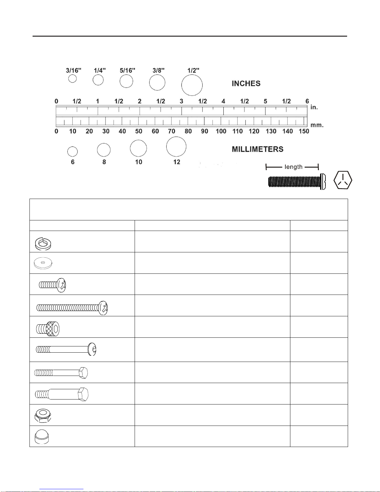
HARDWARE IDENTIFICATION CHART
This chart is provided to help identify the hardware used in the assembly process. Place the washers, the end of the bolts,
or screws on the circles to check for the correct diameter. Use the small scale to check the length of the bolts and screws.
NOTE: The length of all bolts and screws except those with flat heads is measured
from below the head to the end of the bolt or screw. Flat head bolts and
screws are measured from the top of the head to the end of the bolt or screw.
After unpacking the unit, open the hardware bag and make sure that you have all the following items. Some hardware
may be already attached to the part.
Part No. and Description
Q’TY
66 Lock Washer (M8)
4 70 Washer (8x38x2.0t)
4 80 Screw, Round Head (M5xp0.8x15mm)
18 81 Screw, Round Head (M5xp0.8x50mm)
2 83 Bolt, Socket Head (M8xp1.25x10mm)
8
90 Bolt, Button Head (M10xp1.5x85mm)
2
94 Bolt, Hex Head (M8xp1.25x65mm)
4
95 Bolt, Hex Head (M10xp1.5x50mm)
2 104 Nylock Nut (M10xp1.5)
2
105 Nut Cap
2
3
ASSEMBLE INSTRUCTIONS
Place all parts from the box in a cleared area and position them on the floor in front of you. Remove all packing materials
from your area and place them back into the box. Do not dispose of the packing materials until assembly is completed.
Read each step carefully before beginning.
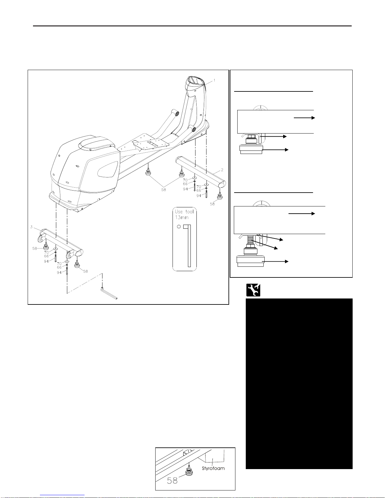
STEP 1
Attach the Leveler (58) to the Front Stabilizer (2) and the Rear
Stabilizer (3).
Be sure to tighten the Leveler (58) securely against the Stabilizers
(2, 3) until screw lines are eliminated as the drawing 1 shows on
the top right corner.
STEP 2
Attach the Front Stabilizer (2) and the Rear Stabilizer (3) onto the
Main Frame (1) and secure with the Washer (8x38x2.0t) (70), the Lock
Washer (M8) (66) and the Bolt, Hex Head (M8xp1.25x65mm) (94) by
using socket wrench as the main assembling drawing shows.
If the equipment is not level, review the LEVELING NOTE on the
right side to level the Leveler (58).
STEP 3
Tighten the Leveler (58) securely against the Main Frame (1).
NOTE: It will be easier to attach the Leveler (58) to the Main Frame (1)
by placing one Styrofoam (or any stationary object) under one side of
the Main Frame (1).
Detailed Lever- drawing 1
Detailed Lever- drawing 2
LEVELING: After placing the
equipment in the intended
location for use, Check the
stability of the equipment. If the
equipment is not level,
reviewing the following
direction:
Loosen the Leveler (58) to
make the Adjustment Plate
become less tight.
Adjust the Leveler (58) for
leveling.
Tighten the Adjustment Plate
securely against the Stabilizer
to lock the Leveler (58) in the
stable position as the drawing
2 shown.
Stabilizer
Adjustment Plate
Leveler (58)
Adjustment Plate
Stabilizer
Leveler (58)
Screw line
4
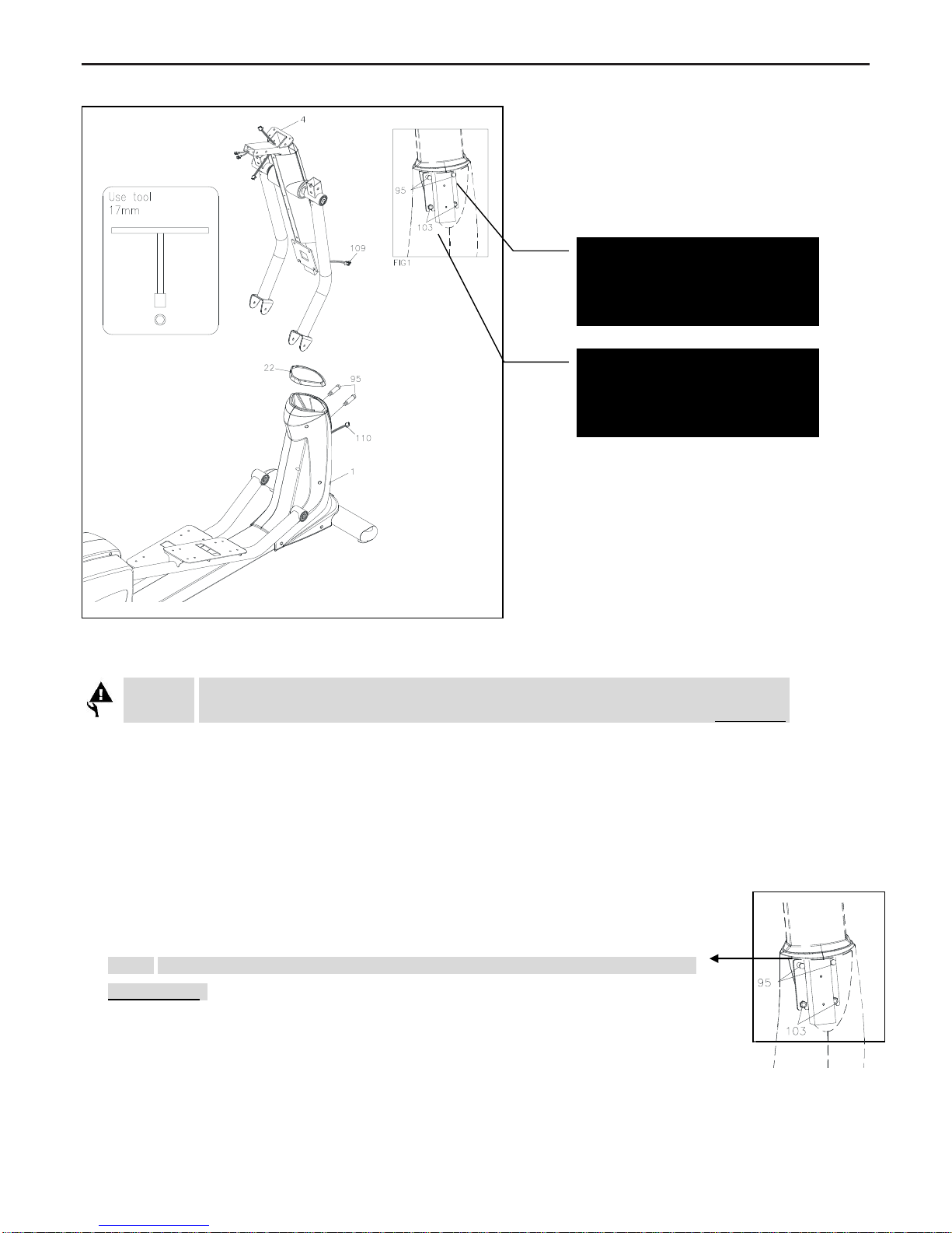
ASSEMBLE INSTRUCTIONS
STEP 4
CAUTION: Be careful not to damage the Middle Connection Wire (109) while assembling Step 4 to 6.
Slide the Upright Sleeve (22) onto the Upright Post (4).
Refer to the drawing above. Make sure the direction of the Upright Sleeve (22) is in the correct position.
STEP 5
a. Check that 2 x Nylon lock Nuts (M10x8t) (103) have preassembled into the front of the Main Frame (1) as FIG1
illustration shows on the top right corner, making sure that the slotted bracket of the upright post slides between the
nuts and the frame.
b. Insert the Upright Post (4) onto the Main Frame (1) and slightly secure with the 2 x Hex Head
Bolts (M10xp1.5x50mm) (95) by using the T-Handle SOCKET WRENCH(17mm) as shown.
NOTE: Please do not fully tighten Bolts (95) or lock nuts (103) until Step. 7 has been
c. COMPLETED
STEP 6
Plug the Middle Connection Wire (109) into the Lower Connection Wire (110).
NOTE: Please do not fully
tighten Bolts (95) until Step. 8
for the easy assembly
NOTE: Do not remove the lock
nuts (103) during assembly

5
ASSEMBLE INSTRUCTIONS
STEP 7
a. Attach the Left Pedal Support Arm
(10) onto the Left Pivoting Arm (8)
and secure with the 1x Button Head
Bolt (M10xp1.5x85mm) (90) and 1 x
Nylon lock Nut (M10xp1.5) (104).
b. Press the Nut Cap (105) onto the
Nylon lock Nut (M10xp1.5) (104).
c. Repeat the above procedure to attach
the Right Pedal Support Arm (11)
onto the Right Pivoting Arm (9).
Note: make sure the bolts are fully
tightened to avoid noise
STEP 8
a. Please go back to fully tighten with the 2 x
Hex Head Bolts
(M10xp1.5x50mm) (95)
and the 2 x Lock nuts
(103) with the T-Handle
SOCKET WRENCH
(17mm) as shown.
b. Attach the Front Decorative Upright Cover
(21) onto the front of the Main Frame (1)
with the 2 x Round Head Screws
(M5xp0.8x50mm) (81).
c. Place the Logo Sticker on the surface of the Front Decorative Upright Cover (21).
A logo sticker is located in one of the hardware boxes.
d. Slide the Upright Sleeve (22) down to cover the open area of the Main Frame (1).
NOTE: Please make sure Bolts (90) are
inserted from the inside of the Pivoting Arm
and the Nuts (104) and Nut Caps (105) are
installed from the outside

6
“ASSEMBLY INSTRUCTIONS”
STEP 9
a. Attach the Left Pedal (33) onto the iron
plate that is located in the middle of the
Left Pedal Support Arm (10) and
secure with 4pcs Bolts
(M8xp1.25x10mm)(83).
b. Place the Non-Slip Pad (34) onto the
Left Pedal (33).
c. Repeat the above procedure (from b. to
c.) to attach Right Pedal and Non-Slip
Pad on the Right Pedal Arm.

7
ASSEMBLE INSTRUCTIONS
STEP 10
CAUTION: Be careful not to
damage the Middle Pulse Sensor
Wire (112) while assembling STEP
10.
Slide the Console Bracket (18) onto
the Front & Back Upright Cover
(44, 45) as the FIG1 illustration
shows on the top left corner.
STEP 11
NOTE: For shipping purpose, the
Bolt, Button Head
(M8xp1.25x12mm) (87) and Lock
Washer (M8) (66) are attached on
the Upright Post (4).
a. Remove the Bolt, Button Head (M8xp1.25x12mm) (87) and Lock Washer (M8) (66) from the Upright
Post (4).
b. Attach the Console Fixed Bracket (43) onto the Upright Post (4) and secure with the Bolt, Button Head
(M8xp1.25x12mm) (87) and Lock Washer (M8) (66).
STEP 12
NOTE: For shipping purpose, the Bolt, Button Head (M8xp1.25x16mm) (88) and Lock Washer (M8) (66) are
attached on the Stationary Handlebar (5).
a. Remove the Bolt, Button Head (M8xp1.25x16mm) (88) and Lock Washer (M8 ) (66) from the Stationary
Handlebar (5).
b. Connect the Middle Pulse Sensor Wire (112) and the Lower Pulse Sensor Wire (113) to the Stationary
Handlebar (5).
c. Insert the Stationary Handlebar (5) into the Upright Post (4) and secure with the Bolt,
Button Head (M8xp1.25x16mm) (88) and Lock Washer (M8) (66).
NOTE: After connecting the wires’ pins, slightly and gently pull two sides of wires to test and
make sure whether the wires are fully connected.

8
ASSEMBLE INSTRUCTIONS
STEP 13
a. Loosen the Screw (M3x10mm) (74) at the
bottom on the console by using the
combination wrench to open the Battery
Door (20).
b. The Console (17) operates with FOUR AA
rechargeable batteries, four batteries are
included in the hardware box.
c. Install rechargeable batteries into the
Console (17).
Make sure the location of positive or
negative battery terminal is correct.
d. Attach the Battery Door (20) onto the back
of the Console (17) and secure with the
Screw (M3x10mm) (74).
STEP 14
a. Connect the Upper Pulse Sensor Wire (111) to the Middle Pulse Sensor Wire (112).
b. Connect the Upper Connection Wire (108) to the Middle Connection Wire (109).
NOTE: The number of wire pin should be the same for both wires to connect with as the following illustration
shown.
STEP 15
a. Place the Console (17) onto the Upright Post (4) and secure with the Screw, Round Head
(M5xp0.8x15mm) (80).
b. Attach the Console Lower Case (19) to the Console (17) under the Stationary Handlebar (5) and secure
with the Screw, Round Head (M5xp0.8x15mm) (80).
STEP 16
Slide the Console Bracket (18) onto the Console (17) and secure with the Screw, Round Head
(M5xp0.8x15mm) (80).
STEP 17
NOTE: For shipping purpose, the Screw, Round Head (M5xp0.8x15mm) (80) are
attached on the Upright Post (4).
a. Remove the Bolt, Button Head (M8xp1.25x15mm) (80) from the Upright Post (4).
b. Attach the Accessory Tray (23) onto the Upright Post (4) and secure with the
Screw, Round Head (M5xp0.8x15mm) (80).
CAUTION: The machine is suitable for
Nickel-Metal Hybird / NI-MH
rechargeable batteries only.
To prevent from any damages,
general or other type of batteries
are not allowed to use.

9
ASSEMBLE INSTRUCTIONS
STEP 18
NOTE: For shipping purpose, the Bolt, Hex Head (M8×p1.25×16mm) (123) are attached on the Left and
Right Upper Handlebar (6, 7).
a. Remove the Bolt, Hex Head (M8×p1.25×16mm) (123) from the Left and Right Upper Handlebar (6, 7).
b. Following the inset drawing, insert the Right Upper Handlebar (7) onto the Right Pivoting Arm (9) and
secure with the Bolt, Hex Head (M8×p1.25×16mm) (123).
c. Repeat the above procedure to insert and secure the Left Upper Handlebar (6) onto the Left Pivoting
Arm (8).
STEP 19
a. Place the Front Rotator Cuff–Pivoting Arm (31) and the Back Rotator Cuff–Pivoting Arm (32) at both
sides of the Right Pivoting Arm (9).
b. Bolt the Rotator Cuffs together with the Screw, Round Head (M5xp0.8x15mm) (80).
c. Repeat the above procedure to place the Front Rotator Cuff–Pivoting Arm (31) and the Back Rotator
Cuff–Pivoting Arm (32) at both sides of the Left Pivoting Arm (8).
For the final step, make sure all the bolts and nuts are tighten securely before using.

10
OPERATIONAL INSTRUCTIONS
A. CONSOLE ANGLE ADJUSTMENT
To get the best angle, user could press the area A or B with the personal need.
B. HOW TO TOW THE SELF-POWERED ELLIPTICAL TRAINER SAFELY
Move the Elliptical Trainer with the moving wheels on the Rear Stabilizer (3). Lift up the Front Stabilizer (2)
with two hands to move the Elliptical Trainer.
Two people are strictly required to move the Elliptical
Trainer together.
Make sure the floor is level while towing the Elliptical
Trainer.
A
B

11
CONDITIONING GUIDELINES
How you begin your exercise program depends on your physical condition. If you have been inactive for several
years, or are severely overweight, you must slowly and increase your time on the 2 in 1 Elliptical / Stepper
gradually: a few minutes per workout.
Initially, you may be able to exercise only for a few minutes in your target zone, however, your aerobic fitness
will improve over the next six to eight weeks. Don’t be discouraged if it takes longer. It’s important to work at
your own pace. Ultimately, you’ll be able to exercise continuously for 30 minutes. The better your aerobic fitness,
the harder you will have to work to stay in your target zone. Please remember these essentials:
˙ Have your doctor review your training and diet programs to advise you of a workout routine you should adopt.
˙ Begin your training program slowly with realistic goals that have been set by you and your doctor.
˙ Monitor your pulse frequently. Establish your target heart rate base on your age and condition.
˙ Set up your 2 in 1 Elliptical / Stepper a flat, even surface at least 3 feet from walls and furniture.
EXERCISE INTENSITY
To maximize the benefits of exercising, it is important to exercise with the proper intensity. The proper intensity
level can be found by using your heart rate as a guide. For effective aerobic exercise, your heart rate should be
maintained at a level between 70% and 85% of your maximum heart rate as you exercise. This is known as
your target zone. You can find your target zone in the table below. Target zones are listed for both
unconditioned and conditioned persons according to age.
During the first few months of your exercise
program, keep your heart rate near the low end
of your target zone as you exercise. After a few
months, your heart rate can be increased
gradually until it is near the middle of your target
zone as you exercise.
To measure your
heart rate manually,
stop exercising but
continue moving
your legs or walking
around and place
two fingers on your wrist. Take a six-second
heartbeat count and multiply the results by 10 to
find your heart rate. For example, if your
six-second heartbeat count is 14, your heart
rate is 140 beats per minute. (A six-second count is used because your heart rate will drop rapidly when you
stop exercising.) Adjust the intensity of your exercise until your heart rate is at the proper level.
Age
Target Heart Rate Zone
(55% ~ 90% of Max.
Heart Rate)
Average Max. Heart
Rate 100%
20
110-180 beats per minute
200 beats per minute
25
107-175 beats per minute
195 beats per minute
30
105-171 beats per minute
190 beats per minute
35
102-166 beats per minute
185 beats per minute
40
99-162 beats per minute
180 beats per minute
45
97-157 beats per minute
175 beats per minute
50
94-153 beats per minute
170 beats per minute
55
91-148 beats per minute
165 beats per minute
60
88-144 beats per minute
160 beats per minute
65
85-139 beats per minute
155 beats per minute
70
83-135 beats per minute
150 beats per minute

12
WARM-UP and COOL-DOWN
Warm-up The purpose of warming up is to prepare your body for exercise and to minimize injuries. Warm up for
two to five minutes before strength-training or aerobic exercising. Perform activities that raise your heart rate and
warm the working muscles. Activities may include brisk walking, jogging, jumping jacks, jump rope, and running in
place.
Stretching Stretching while your muscles are warm after a proper warm-up and again after your strength or
aerobic training session is very important. Muscles stretch more easily at these times because of their elevated
temperature, which greatly reduces the risk of injury. Stretches should be held for 15 to 30 seconds. Do not bounce.
Suggested Stretching Exercise
Lower Body Stretch
Place feet shoulder-width
apart and lean forward.
Keep this position for 30
seconds using the body as a
natural weight to stretch the
backs of the legs. DO NOT
BOUNCE! When the pull on
the back
of the legs lessen, try a lower
position gradually.
h
Floor Stretch
While sitting on the floor,
open the legs as wide as
possible. Stretch the upper
body toward the knee on the
right leg by using your arms
to pull your chest to your
thighs. Hold this stretch 10
to 30 seconds. DO NOT
BOUNCE! Do this stretch 10
times. Repeat the stretch
with the left leg.
Bent Torso Pulls
While sitting on the floor,
have legs apart one leg
straight and one knee bent.
Pull the chest down to touch
the thigh on the leg that is
bent and twist at the waist.
Hold this position at least 10
seconds. Repeat 10 times on
each side.
Bent Over Leg Stretch
Stand with feet
shoulder-width apart and
lean forward as illustrated.
Using the arms, gently pull
the upper body towards the
right leg. Let the head hang
down. DO NOT BOUNCE!
Hold the position a minimum
of 10 seconds. Repeat
pulling the upper body to the
left leg. Do this stretch
several times slowly.
Remember always to check with your physician before starting any exercise program.
Cool-Down The purpose of cooling down is to return the body to its normal, or near normal, resting state at the
end of each exercise session. A proper cool-down slowly lowers your heart rate and allows blood to return to the
heart. Your cool-down should include the stretches listed above and should be completed after strength-training
session.

13
PARTS LIST
NO.
Item Name
Q'TY
1
Main Frame
1
2
Front Stabilizer
1
3
Rear Stabilizer
1
4
Upright Post
1
5
Stationary Handlebar
1
6
Left Upper Handlebar
1
7
Right Upper Handlebar
1
8
Left Pivoting Arm
1
9
Right Pivoting Arm
1
10
Left Pedal Support Arm
1
11
Right Pedal Support Arm
1
12
Front Left-Side Cover
1
13
Front Right-Side Cover
1
14
Rear Left-Side Cover
1
15
Rear Right-Side Cover
1
16
Main Frame Base Cover
1
17
Console
1
18
Console Bracket
1
19
Console Lower Case
1
20
Battery Door
1
21
Front Decorating Upright Cover
1
22
Upright Sleeve
1
23
Accessory Tray
1
24
Pulse Sensor Top Housing
2
25
Pulse Sensor Bottom Housing
2
26
Pulse Sensor Plate Assembly
4
27
Foam Grip Assembly (40mm)
2
28
Stationary Handlebar Plug
(ψ31.8mm)
2
29
Foam Grip Assembly (225mm)
2
30
Inner Rotator Cuff-Pivoting Arm
2
31
Front Rotator Cuff-Pivoting Arm
2
32
Back Rotator Cuff-Pivoting Arm
2
33
Pedal Upper Case
2
34
Non-Slip Pad
2
NO.
Item Name
Q'TY
35
Roller
2
36
EndCap (50x100mm)
4
37
Pulley (120mm)
1
38
Pulley (235mm)
1
39
Magnet
1
40
Belt (1126mm J8)
1
41
Belt (1059mm J8)
1
42
Square Plug
1
43
Console Fixed Bracket
1
44
Front Aluminum Upright Cover
1
45
Back Aluminum Upright Cover
1
46
Upper Pivot Shaft Spacer
2
47
Pedal Arm Spacer
2
48
Linkage Spacer
4
49
Left Crank
1
50
Right Crank
1
51
Crank Axle
1
52
Mounting Plate
2
53
Generator
1
54
Controller
1
55
Resistor
1
56
Drive Shaft
1
57
Bearing Stand
1
58
Leveler
5
59
Pedal Support Arm Connector
2
60
Bearing (6004)
12
61
Bearing (6905)
4
62
Eye Bolt
2
63
Tension Bracket
2
64
C Ring
2
65
Square Key
1
66
Lock Washer (M8)
17
67
Washer (8x26x2.0t)
3
68
Washer (8x23x2.0t)
1
69
Washer (8x30x2.0t)
2

14
PARTS LIST
NO.
Item Name
Q'TY
70
Washer (8×38×2.0t)
4
71
Washer (10×23×2.0t)
2
72
Washer (21×30×1.0t)
5
73
Hex Socket Cap Screw
(M8×1.25×10mm)
4
74
Screw (M3×10mm)
1
75
Screw (M4×20mm)
4
76
Screw (M5×18mm)
23
77
Bolt, Button Head
(M6×p1.0×12mm)
2
78
Bolt, Button Head (35mm)
2
79
Screw, Round Head (M3×35mm)
4
80
Screw, Round Head
(M5×p0.8×15mm)
20
81
Screw, Round Head
(M5×p0.8×50mm)
2
82
Screw, Round Head
(M5×p0.8×75mm)
2
83
Bolt, Socket Head
(M8×p1.25×10mm)
8
84
Bolt, Socket Head
(M8×p1.25×65mm)
2
85
Bolt, Socket Head
(M8×p1.25×75mm)
2
86
Bolt, Socket Head
(M8×p1.25×100mm)
2
87
Bolt, Button Head
(M8×p1.25×12mm)
4
88
Bolt, Button Head
(M8×p1.25×16mm)
8
89
Bolt, Button Head
(M8×p1.5×50mm)
2
90
Bolt, Button Head
(M8×p1.5×85mm)
2
91
Carriage Bolt (M8×p1.25×75mm)
4
92
Bolt, Hex Head
(M8×p1.25×15mm)
1
NO.
Item Name
Q'TY
93
Bolt, Hex Head
(M8×p1.25×15mm)
4
94
Bolt, Hex Head
(M8×p1.25×65mm)
4
95
Bolt, Hex Head
(M10×p1.5×50mm)
2
96
Flange Nut (M10)
1
97
Nut (M10×p1.25)
1
98
Nut (M3)
4
99
Nut (M8×p1.25)
1
100
Nylock Nut (M6×p1.0)
2
101
Nylock Nut (M8×p1.25×6.2t)
4
102
Nylock Nut (M8×p1.25)
8
103
Nylock Nut (M10×p1.5×8t)
2
104
Nylock Nut (M10×p1.5)
4
105
Nut Cap
2
106
Generator Wire (3pin×700mm)
2
107
Sensor Wire & Stand
(2pin×600mm)
1
108
Upper Connection Wire
(4pin×300mm)
1
109
Middle Connection Wire
(4pin×900mm)
1
110
Lower Connection Wire
(4pin×2100mm)
1
111
Upper Pulse Sensor Wire
(4pin×300mm)
1
112
Middle Pulse Sensor Wire
(4pin×300mm)
1
113
Lower Pulse Sensor Wire
(2pin×300mm/400mm)
2
115
Handheld Dome Plug
2
121
Axle Spacer
1
122
Nylock Nut (M20×p1.0)
1
123
Bolt, Hex Head
(M8×p1.25×16mm)
8

PRODUCT PARTS DRAWING
 Loading...