

STI PR-7001 Owner's Manual
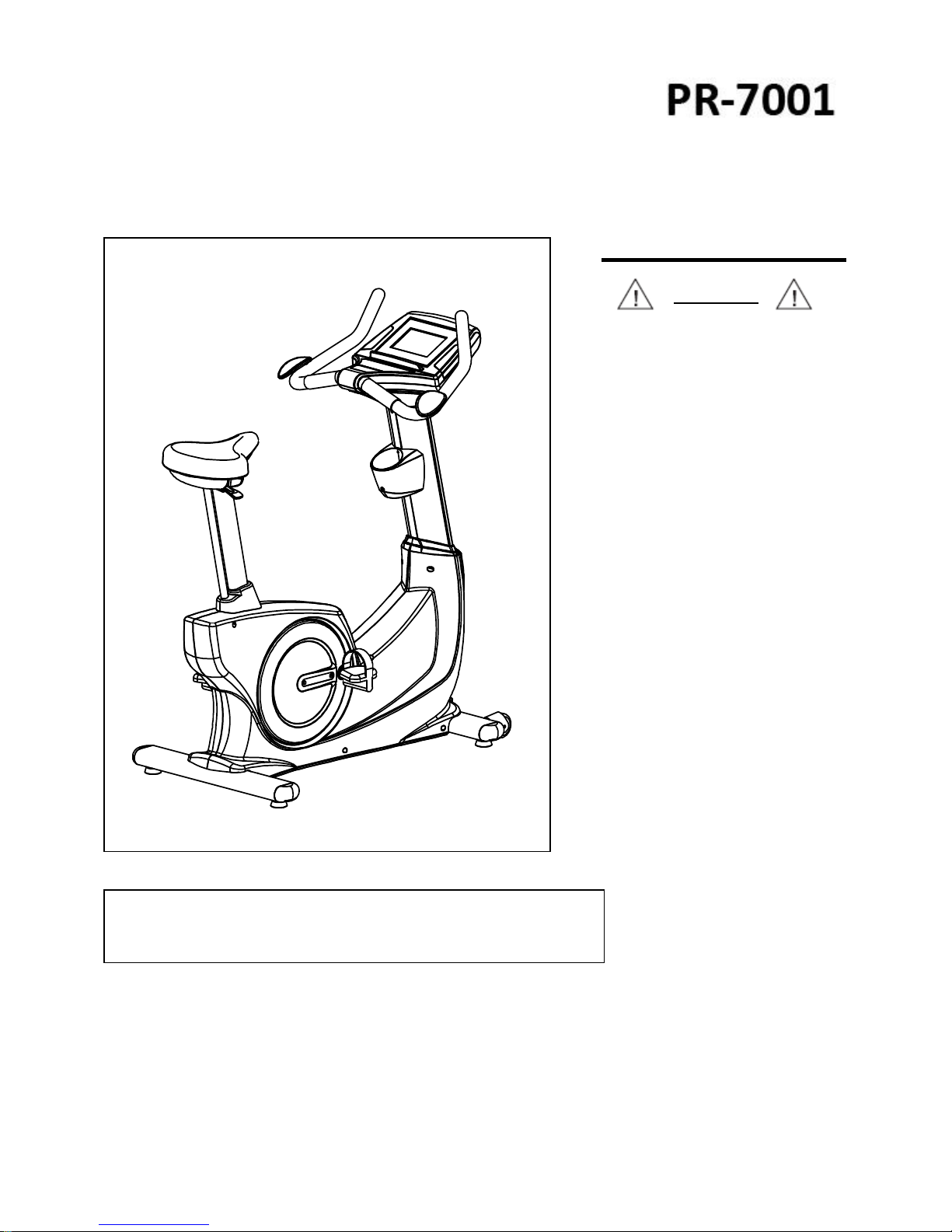
Product May Vary Slightly Different From Picture.
v. III.3
Owners’ Manual
Exercise can present a health
risk. Consult a physician before
beginning any exercise program
with this equipment.
If you feel faint or dizzy,
immediately discontinue use of
this equipment. Serious bodily
injury can occur if this
equipment is not assembled and
used correctly. Serious bodily
injury can also occur if all
instructions are not followed.
Keep others and pets away from
equipment when in use. Always
make sure all bolts and nuts are
tightened prior to each use.
Follow all safety instructions in
this manual.
WARNING
CAUTION:
Weight on this product should not exceed 181 kgs/ 400 lbs
MADE IN TAIWAN

1
SAFETY INSTRUCTIONS
WARNING: To reduce the risk of serious injury, read the following Safety Instructions before using the
Upright Bike.
1. Read all warnings posted on the Upright Bike.
2. Read this Owner's Manual and follow it carefully before using the Upright Bike. Make sure that it is properly
assembled and tightened before use.
3. We recommend that two people be available for assembly of this product.
4. Keep children away from the Upright Bike. Do not allow children to use or play on the Upright Bike. Keep
children and pets away from the Upright Bike when it is in use.
5. It is recommended that you place this exercise equipment on an equipment mat.
6. Set up and operate the Upright Bike on a solid level surface. Do not position the Upright Bike on loose rugs or
uneven surfaces.
7. Inspect the Upright Bike for worn or loose components prior to use.
8. Tighten/replace any loose or worn components prior to using the Upright Bike.
9. Consult a physician prior to commencing an exercise program. If, at any time during exercise, you feel faint,
dizzy, or experience pain, stop and consult your physician.
10. Follow your physician's recommendations in developing your own personal fitness program.
11. Always choose the workout which best fits your physical strength and flexibility level. Know your limits and train
within them. Always use common sense when exercising.
12. Before using this product, please consult your personal physician for a complete physical examination.
13. Do not wear loose or dangling clothing while using the Upright Bike.
15. Be careful to maintain your balance while using, mounting, dismounting, or assembling the Upright Bike, loss
of balance may result in a fall and serious bodily injury.
16. Keep both feet firmly and securely on the Foot Pedals while exercising.
17. The Upright Bike should not be used by persons weighing over 400 pounds /181 kgs.
18. The Upright Bike should be used by only one person at a time.
19. Maintenance: Replace the defective components immediately and/or keep the equipment out of use until repair
the equipment completely.
20. Make sure that adequate space is available for access to and passage around the Upright Bike; keep at least
a distance of 1 meter from any obstruction object while using the machine.
WARNING: Before starting any exercise or conditioning program you should consult with your personal physician
to see if you require a complete physical exam. This is especially important if you are over the age of 35, have
never exercised before, are pregnant, or suffer from any illness. READ AND FOLLOW THE SAFETY
PRECAUTIONS. FAILURE TO FOLLOW THESE INSTRUCTIONS CAN RESULT IN SERIOUS BODILY
INJURY.
2
BEFORE YOU BEGIN
Thank you for choosing the self-powered UPRIGHT
BIKE. We take great pride in producing this quality
product and hope it will provide many hours of quality
exercise to make you feel better, look better and enjoy
life to its fullest.
Yes, it's a proven fact that a regular exercise program
can improve your physical and mental health.
Too often, our busy lifestyles limit our time and
opportunity to exercise. The UPRIGHT BIKE provides a
convenient and simple method to begin your assault on
getting your body in shape and achieving a happier and
healthier lifestyle.
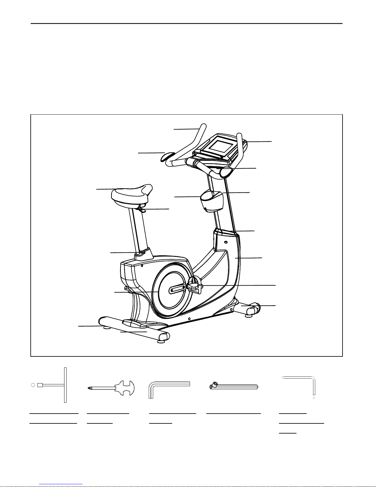
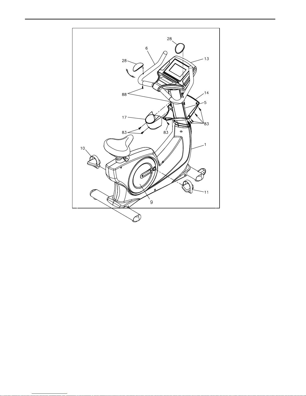
Before reading further, please review the drawing
below and familiarize yourself with the parts that are
labeled. Read this manual carefully before using the
UPRIGHT BIKE.
THE FOLLOWING TOOLS ARE INCLUDED FOR ASSEMBLY:
T-HAND SOCKET
WRENCH (17MM)
ALLEN WRENCH
(M5, M6)
SOCKET WRENCH
COMBINATION
WRENCH
Handlebar
Hand Wrist Pad
Console
Adjustment
Bar
Console Bracket
Upright Post
Seat Cap
Crank Cover
Upright Sleeve
Main Frame
Right Pedal
Front Stabilizer
Rear Stabilizer
Leveler
Accessory
Tray
Seat
PHILLIPS
SCREWDRIVER
(6mm)
3
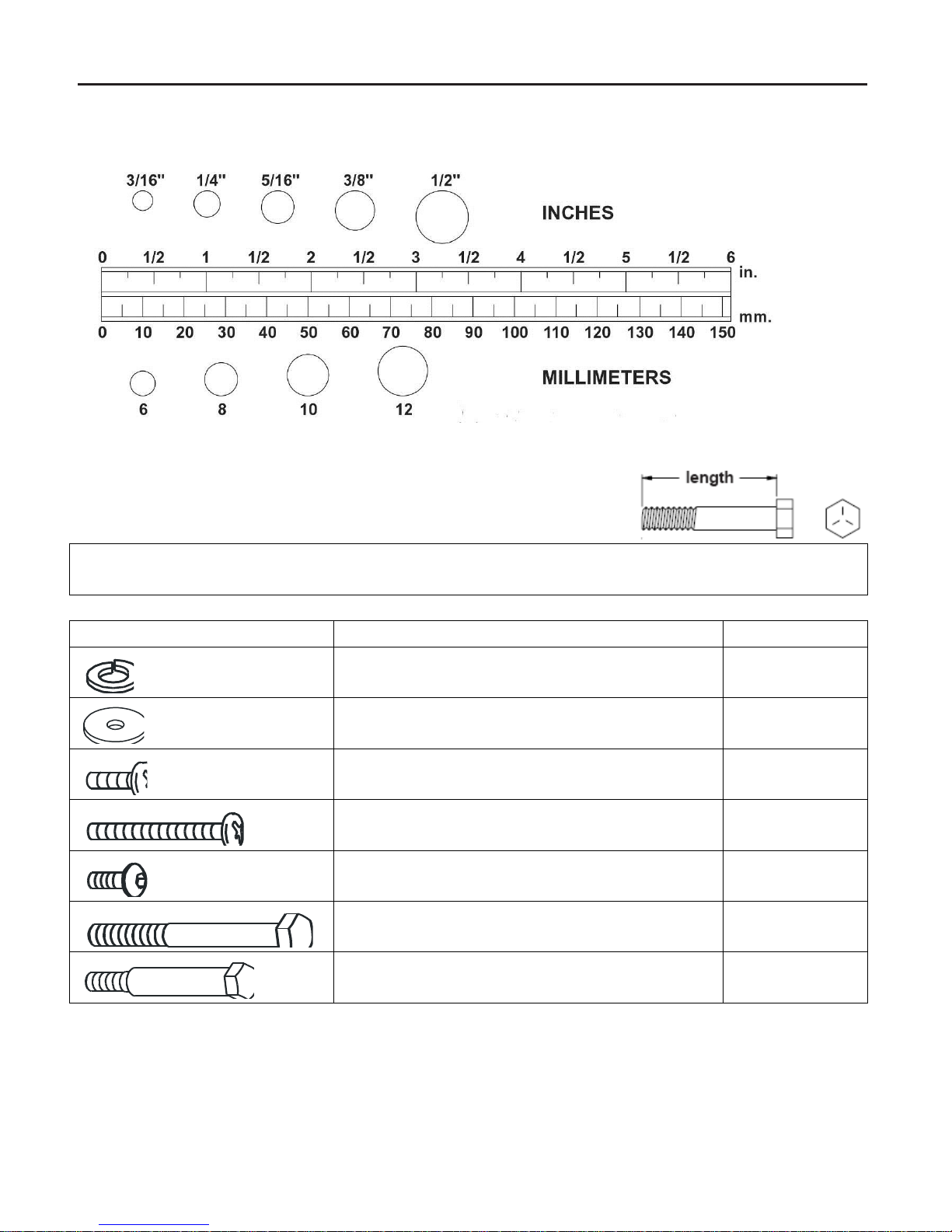
HARDWARE IDENTIFICATION CHART
This chart is provided to help identify the hardware used in the assembly process. Place the washers, the end of the bolts, or
screws on the circles to check for the correct diameter. Use the small scale to check the length of the bolts and screws.
NOTICE:
The length of all bolts and screws except those with flat heads is measured from
below the head to the end of the bolt or screw. Flat head bolts and screws
are measured from the top of the head to the end of the bolt or screw.
After unpacking the unit, open the hardware bag and make sure that you have all the following items. Some hardware
may be already attached to the part.
Part No. and Description
Qty
78 Lock Washer (M8)
4
73 Washer (8x38x2.0t)
4 83 Screw, Round Head (M5xp0.8x15mm)
10 84 Screw, Round Head (M5xp0.8x50mm)
2 88 Bolt, Button Head (M6xp1.0x12mm)
2 97 Bolt, Hex Head (M8xp1.25x65mm)
4
99 Bolt, Hex Head (M10xp1.5x50mm)
2
4
ASSEMBLE INSTRUCTIONS
Place all parts from the box in a cleared area and position them on the floor in front of you. Remove all packing
materials from your area and place them back into the box. Do not dispose of the packing materials until
assembly is completed. Read each step carefully before beginning.
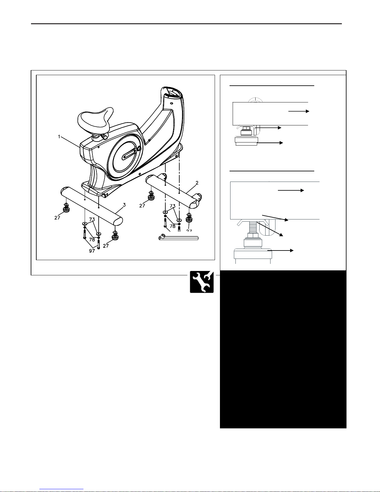
STEP 1
Attach the Leveler (27) to the Front
Stabilizer (2) and the Rear Stabilizer (3.)
Be sure to tighten the Leveler (27)
securely against the Stabilizers (2, 3) until screw lines
are eliminated as the drawing 1 shown.
STEP 2
Attach the Front Stabilizer (2) and the Rear Stabilizer (3)
onto the Main Frame (1) and secure with the Washer
(8x38x2.0t)(73), the Lock Washer (M8)(78) and the Bolt,
Hex Head (M8xp1.25x65mm)(97) by using socket wrench
as the main assembling drawing shows.
If the bike is not level, review the LEVELING NOTE on
the right side to level the Levelers (27.)
Detailed Lever- drawing 1
Detailed Lever- drawing 2
Adjustment Plate
Stabilizer
Leveler (27)
LEVELING: After placing the bike
in the intended location for use,
check the stability of the bike. If the
bike is not level, reviewing the
following direction:
Loosen the Leveler (27) to make
the Adjustment Plate become less
tight.
Adjust the Leveler (27) for leveling.
Tighten the Adjustment Plate
securely against the Stabilizer to
lock the Leveler (27) in stable
position as the drawing 2 shown.
Screw line
Stabilizer
Adjustment Plate
Leveler (27)
5
ASSEMBLE INSTRUCTIONS
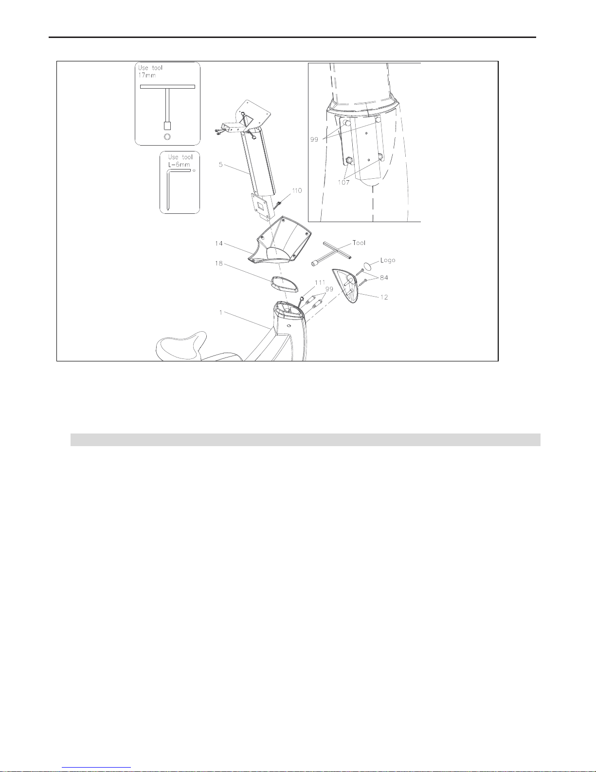
STEP 3
Slide the Console Bracket (14) and the Upright Sleeve (18) onto the Upright Post (5.)
Make sure the direction of the Upright Post (5) is in the correct direction as shown.
Be careful not to damage the Middle Connection Wire (110) while doing assembly Step 3 to 4.
STEP 4
a. Make sure 2 pcs Nylock Nuts (M10) (107) have already inserted into the front of the Main Frame (1)
as the illustration shown on the top right corner
b. Insert the Upright Post (5) into the Main Frame (1) and secure with the Bolt, Hex Head
(M10xp1.5x50mm)(99) by using the T-HEAD SOCKET WRENCH (17MM) as shown.
STEP 5
a. Connect the Middle Connection Wire (110) to the Lower Connection Wire (111).
b. Attach the Front Decorating Upright Cover (12) onto the front of the Main Frame (1) with the
Screw, Round Head (M5xp0.8x50mm)(84.)
c. Paste a Logo Sticker on the surface of the Front Decorating Upright Cover (12.)
A logo sticker is included in the hardware box.
d. Slide the Upright Sleeve (18) down to cover the open area of the Main Frame (1.)
6
ASSEMBLE INSTRUCTIONS
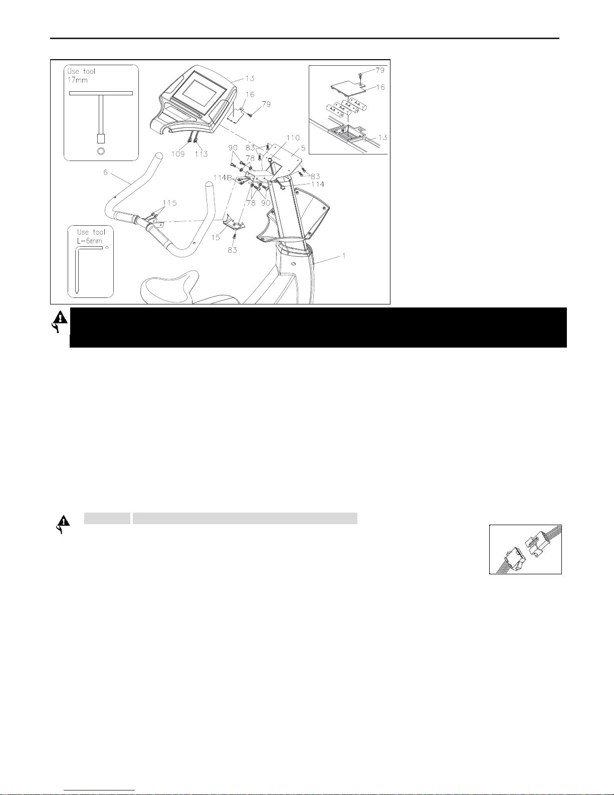
STEP 6
a. Loosen the Screw (M3x10mm)
(79) at the bottom on the
console by using the
combination wrench to open the
Battery Door (16).
b. The Console (13) operates with
FOUR AA rechargeable
batteries, four batteries are
included in the hardware box.
c. Install rechargeable batteries into the Console (13).
Make sure the location of positive or negative battery terminal is correct.
d. Attach the Battery Door (16) onto the back of the Console (13) and secure with the Screw (M3x10mm)
(79).
STEP 7
a. Connect the Lower Pulse Sensor Wire (115) to the Middle Pulse Sensor Wire (114B).
b. Remove the Lock Washer (M8)(78) and Bolt, Button Head (M8xp1.25x16mm) (90) from the Upright
Post (5).
c. Insert the Handlebar (6) into the Upright Post (5) and secure with the Lock Washer (M8)(78) and Bolt,
Button Head (M8xp1.25x16mm)(90) on each side as the drawing shown.
CAUTION: Be careful not to damage wires during assembly.
STEP 8
a. Connect the Upper Pulse Sensor Wire (113) to the Middle Pulse Sensor Wire (114).
b. Connect the Upper Connection Wire (109) to the Middle Connection Wire (110).
Note the number of wire pin should be the same for both wires to connect with as the illustration shown below
STEP 9
Place the Console (13) onto the Upright Post (5) and secure with the Screw, Round Head
(M5xp0.8x15mm)(83.)
STEP 10
Attach the Console Lower Case (15) to the Console (13) and secure with the Screw, Round Head
(M5xp0.8x15mm)(83.)
CAUTION: The machine is suitable for Nickel-Metal Hybird / NI-MH rechargeable batteries
only. General or other types of batteries are not allowed to use.
7
ASSEMBLE INSTRUCTIONS
STEP 11
Slide the Console Bracket (14) onto the Console (13) and secure with the Screw, Round
Head (M5xp0.8x15mm)(83.)
STEP 12
a. Place the Hand Wrist Pad (28) onto the Handlebar (6.)
b. Swing the Hand Wrist Pad (28) to the most suitable position.
c. Secure it with the Bolt, Button Head (M6xp1.0x12mm)(88.)
STEP 13
a. Remove the Screw, Round Head (M5xp0.8x15mm)(83) from the Upright Post(5).
b. Attach the Accessory Tray (17) onto the Upright Post (5) and secure with the Screw, Round Head
(M5xp0.8x15mm)(83.)
STEP 14
Thread the Right Pedal (11) clockwise onto the Right Crank located inside the Right Crank Cover (9)
as shown. Tighten the pedal securely. Repeat the same procedure to thread and tighten the Left Pedal
(10) counter-clockwise onto the Left Crank as shown.
8
23
OPERATIONAL INSTRUCTIONS
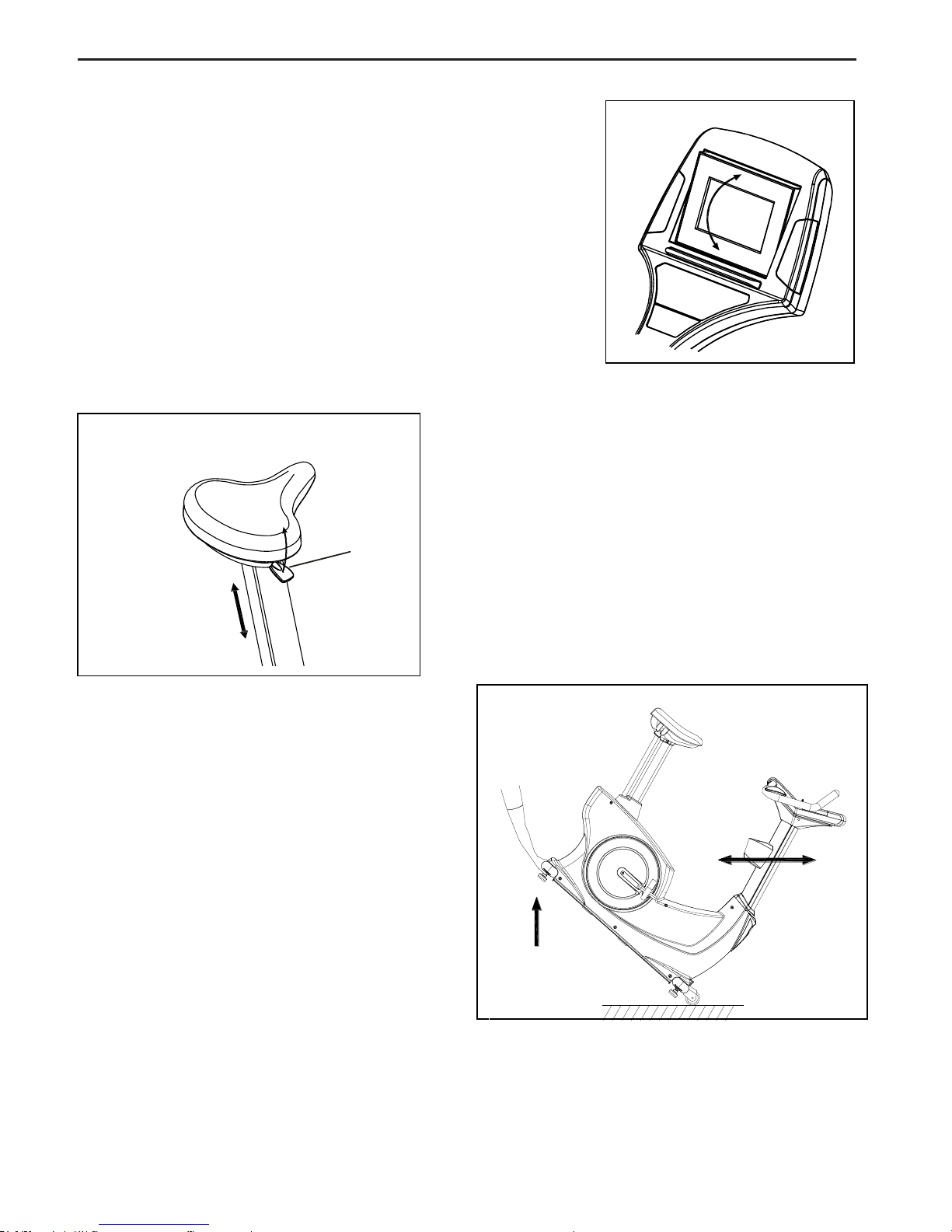
A. CONSOLE ANGLE ADJUSTMENT
To get the best angle, user could press the area A or B with the
personal need.
B. SEAT POST ADJUSTMENT
USER CAN ADJUST THE SEAT HEIGHT WHILE BE
SEATED
While be seated, pull the Adjustment Bar (23) up to
adjust the seat height.
Seat downward to lower the seat height or slight
move the body upward to raise the seat height.
Once adjusting to the proper position, release the
Adjustment Bar (23) until hearing the “click” sound.
C. HOW TO TOW THE UPRIGHT BIKE SAFELY
Hold the Rear Stabilizer (3) up with two hands
and tow the upright bike to the desired place
carefully.
Make sure the floor is level while towing the
upright bike.
A
B
9
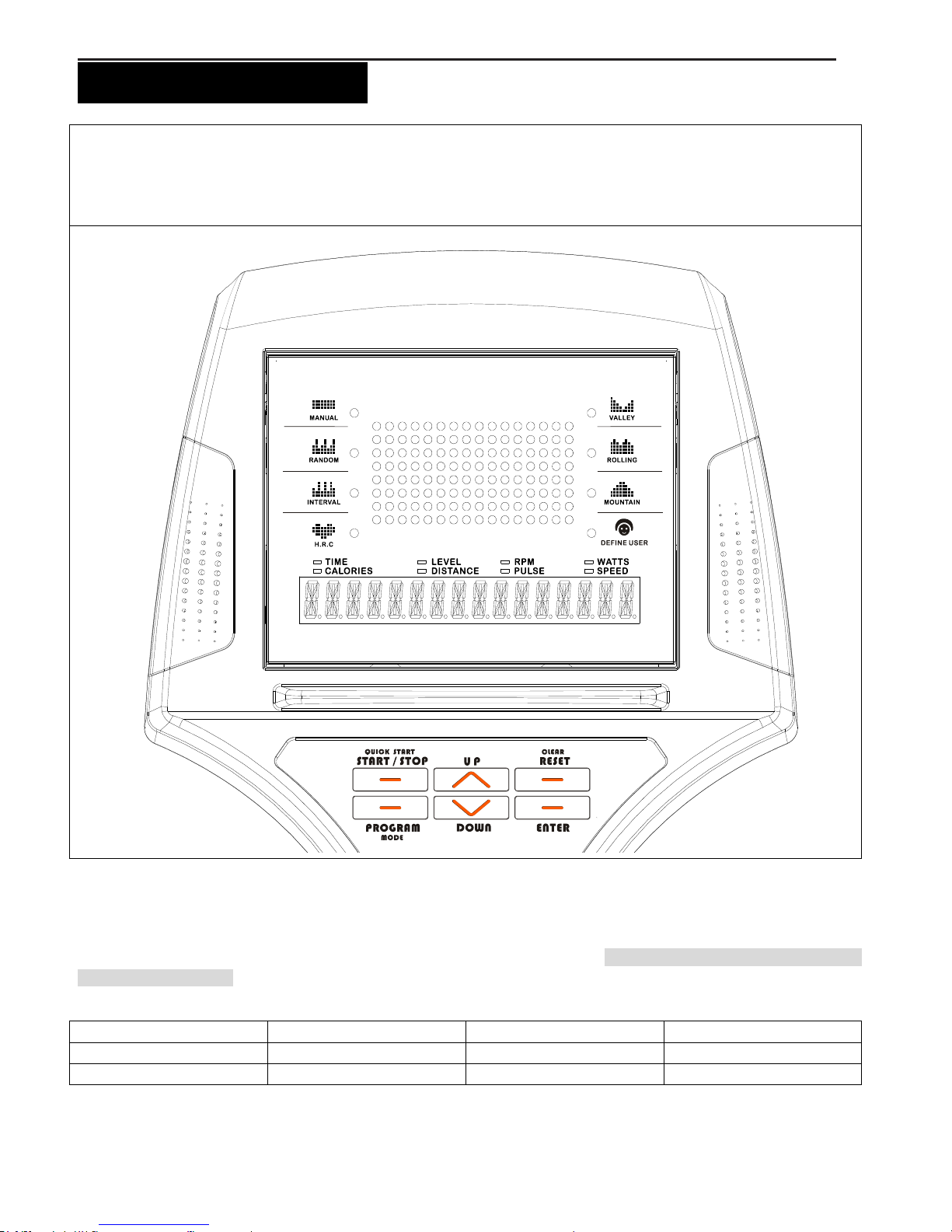
“CONSOLE INSTRUCTIONS”
Take a few minutes to review the console layout. Below is an overview of the console’s features and functions
We recommend that you use the console to help vary your workout routine and keep you focused on your process
toward your fitness goals. The console can become an important source of motivation and interest which will help
keep you on track
Power ON
Pedaling to activate the console.
Power Off
The console would automatically go to SLEEP mode after 1 minutes of inactivity. NOTE: the item will keep power on if
you continue pedaling
Program List
MANUAL PROGRAM
RANDOM PROGRAM
INTERVAL PROGRAM
H.R.C. PROGRAM (65%)
H.R.C. PROGRAM (85%)
VALLEY PROGRAM
ROLLING PROGRAM
MOUNTAIN PROGRAM
DEFINE USER 1
DEFINE USER 2
DEFINE USER 3
DEFINE USER 4
10
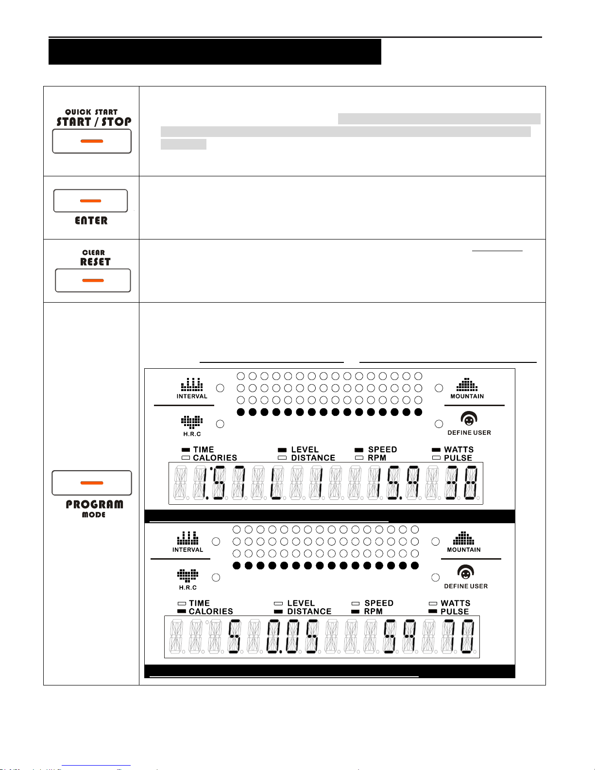
“CONSOLE INSTRUCTIONS – CONSOLE BUTTONS ”
Console Buttons
a. Press START/STOP to begin your exercise.
b. Press START/PAUSE again to stop and pause all functions during your exercise program.
All the dates on the display will then freeze. The console would automatically go to SLEEP
mode after 1 minutes of inactivity (NOTE: the item will keep power on if you continue
pedaling) .
c. Without choosing any programs, directly press QUICK START, MANUAL program will be
selected to start workout.
Press ENTER to confirm the setting values of TIME, DISTANCE, CALORIES, AGE, TARGET
HEART RATE and INTERVAL LEVEL.
Press CLEAR RESET, all the date will return to 0 and the console will return to POWER ON
status.
a. Press PROGRAM/MODE to select the program (MANUAL, RANDOM, INTERVAL, H.R.C.,
VALLEY, ROLLING, MOUNTAIN, DEFINE USER PROGRAM).
b. During workout (after pressing START/PAUSE), the user could press PROGRAM/MODE
to review TIME, LEVEL, SPEED and WATTS, or CALORIES, DISTANCE, RPM and PULSE.
TIME, LEVEL, SPEED, WATTS will show at the same time
CALORIES, DISTANCE, RPM, PULSE will show at the same time
 Loading...