

Page 1
Installation and Operating Manual
RF
Capacitance
Level
Measurement
Kotron
®
Model 811
RF Point Level Sensor
Page 2

50-608 Kotron Model 811 RF Point Level Sensor
Read this Manual Before Installing
This manual provides information on the Kotron
Model 811 RF Point Level Sensor. It is important that all
instructions are read carefully and followed in sequence.
Detailed instructions are included in the Installation
section of this manual.
Conventions Used in this Manual
Certain conventions are used in this manual to convey
specific types of information. General technical material,
support data, and safety information are presented in
narrative form. The following styles are used for notes,
cautions, and warnings.
Notes
Notes contain information that augments or clarifies
an operating step. Notes do not normally contain
actions. They follow the procedural steps to which
they refer.
Cautions
Cautions alert the technician to special conditions that
could injure personnel, damage equipment, or reduce
a component’s mechanical integrity. Cautions are also
used to alert the technician to unsafe practices or the
need for special protective equipment or specific materials. In this manual, a caution box indicates a potentially hazardous situation which, if not avoided, may
result in minor or moderate injury.
Warnings
Warnings identify potentially dangerous situations or
serious hazards. In this manual, a warning indicates an
imminently hazardous situation which, if not avoided,
could result in serious injury or death.
WARNING! Explosion hazard. Do not connect or dis-
connect equipment unless power has been switched off or
the area is known to be non-hazardous.
Safety Messages
The Kotron Model 811 system may be properly installed
in Category II, Pollution Degree 2 installations. Follow all
standard industry procedures for servicing electrical and
computer equipment when working with or around high
voltage. Always shut off the power supply before touching
any components. Although high voltage is not present in
this system, it may be present in other systems.
Electrical components are sensitive to electrostatic discharge. To prevent equipment damage, observe safety
procedures when working with electrostatic sensitive
components.
Low Voltage Directive
For use in Category II installations. If equipment is used
in a manner not specified by manufacturer, protection
provided by equipment may be impaired.
Notice of Trademark, Copyright, and Limitations
Kotron is a registered trademark of Magnetrol
International, Incorporated. Kotron Model 811 RF Point
Level Sensor is a tradename of Magnetrol International,
Incorporated.
Copyright © 2006 Magnetrol International, Incorporated.
Magnetrol reserves the right to make changes to the product described in this manual at any time without notice.
Magnetrol makes no warranty with respect to the accuracy
of the information in this manual.
Warranty
All Magnetrol/STI electronic level and flow controls are
warranted free of defects in materials or workmanship for
one full year from the date of original factory
shipment.
If returned within the warranty period; and, upon
factory inspection of the control, the cause of the claim is
determined to be covered under the warranty; then,
Magnetrol/STI will repair or replace the control at
no cost to the purchaser (or owner) other than
transportation.
Magnetrol/STI shall not be liable for misapplication, labor
claims, direct or consequential damage or expense arising
from the installation or use of equipment. There are no
other warranties expressed or implied, except special written warranties covering some Magnetrol/STI products.
Quality Assurance
The quality assurance system in place at Magnetrol/STI
guarantees the highest level of quality throughout the
company. Magnetrol/STI is committed to providing full
customer satisfaction both in quality products and
quality service.
Magnetrol’s quality assurance system
is registered to ISO 9001 affirming
its commitment to known international quality standards providing
the strongest assurance of product/
service quality available.
Page 3

Table of Contents
1.0 Complete Installation
1.1 Unpacking ..............................................................1
1.2 Electrostatic Discharge (ESD) Handling Procedure ....1
1.3 Before You Begin ....................................................2
1.3.1 Site Preparation ...............................................2
1.3.2 Equipment and Tools ......................................2
1.3.3 Operational Considerations.............................2
1.4 Mounting ..................................................................3
1.4.1 Horizontal Mounting ......................................4
1.4.2 Vertical Mounting ...........................................4
1.5 Probe Installation.......................................................5
1.5.1 Installing a Guarded Probe ..............................5
1.5.2 Installing a Standard Probe ..............................5
1.5.3 Installing a Flexible Probe................................5
1.6 Installing a Remote Mount Unit...............................6
1.6.1 Remote Mount with Guarded Probe ...............6
1.6.1.1 Electronic Housing ....................................6
1.6.1.2 Probe Housing Connections......................7
1.6.2 Remote Mount with Rigid and
Flexible Probes.................................................7
1.6.2.1 Electronic Housing ....................................7
1.6.2.2 Probe Housing Connections......................7
1.7 Wiring .......................................................................8
1.7.1 Probe Wiring...................................................8
1.7.2 Electrical Wiring..............................................9
1.7.3 Operating Mode Selection...............................9
1.7.4 Relay Wiring Chart ......................................10
1.8 Calibration — Narrow Differential.........................10
1.8.1 Set Point Adjustment Alarm ..........................10
1.8.2 Low Level Alarm Fail-safe Low – with no
media on the probe .......................................11
1.8.3 Low Level Alarm Fail-safe Low – with
media on the probe .......................................12
1.8.4 High Level Alarm Fail-safe High – with
no media on the probe ..................................12
1.8.5 High Level Alarm Fail-safe High – with
media on the probe .......................................12
1.8.6 Time Delay....................................................12
1.9 Calibration — Wide Differential ............................13
1.9.1 Set Point Adjustment Control .......................13
1.9.2 Time Delay....................................................15
2.0 Reference Information ................................................16
2.1 Description..............................................................16
2.2 Theory of Operation...............................................16
2.3 Troubleshooting.......................................................16
2.3.1 No Signal with Level Change........................16
2.3.2 Probe..............................................................16
2.3.3 Switch Chatter ...............................................17
2.4 Agency Approvals ....................................................18
2.4.1 Agency Specifications – Intrinsically Safe
Installation ....................................................19
2.4.2 Agency Specifications – Explosion Proof
Installation ....................................................19
2.5 Parts.........................................................................20
2.5.1 Replacement Parts .........................................20
2.6 Specifications ...........................................................21
2.6.1 Functional .....................................................21
2.6.2 Physical .........................................................22
3.0 Model Numbers.........................................................23
NOTES.............................................................................24
Kotron Model 811
RF Point Level Sensor
Page 4
50-608 Kotron Model 811 RF Point Level Sensor
1
1.0 Complete Installation
This section provides detailed procedures for properly
installing, configuring, and, as needed, troubleshooting the
Kotron Model 811 RF Point Level Sensor.
1.1 Unpacking
Unpack the instrument carefully. Make sure all components have been removed from the packing material.
Check all the contents against the packing slip and report
any discrepancies to the factory. Before proceeding with
the installation, do the following:
• Inspect all components for damage. Report any damage
to the carrier within 24 hours.
• Make sure the nameplate model number agrees with the
packing slip and purchase order.
• Record the model and serial numbers for future
reference when ordering parts.
Model Number _________________________________
Serial Number __________________________________
1.2 Electrostatic Discharge (ESD)
Handling Procedure
Magnetrol’s electronic instruments are manufactured to the
highest quality standards. These instruments use electronic
components that may be damaged by static electricity present in most work environments.
The following steps are recommended to reduce the risk of
component failure due to electrostatic discharge.
• Ship and store circuit boards in anti-static bags. If an antistatic bag is not available, wrap the board in aluminum
foil. Do not place boards on foam packing materials.
• Use a grounding wrist strap when installing and removing
circuit boards. A grounded workstation is recommended.
• Handle circuit boards only by the edges. Do not touch
components or connector pins.
• Make sure that all electrical connections are completely
made and none are partial or floating. Ground all
equipment to a good, earth ground.
Page 5

50-608 Kotron Model 811 RF Point Level Sensor
2
1.3 Before You Begin
1.3.1 Site Preparation
Each Kotron Model 811 sensor is built to match the
specific physical specifications of the required installation.
Make sure the probe connection is correct for the threaded
or flanged mounting on the vessel or tank where the transmitter will be placed. See Mounting, Section 1.4.
Make sure that the wiring between the power supply
and the Model 811 sensor is complete and correct for
the type of installation. See Specifications, Section 2.6.
When installing the Model 811 sensor in a general
purpose or hazardous area, all local, state, and federal
regulations and guidelines must be observed. See Wiring,
Section 1.7.
1.3.2 Equipment and Tools
No special equipment or tools are required to install
the Model 811 sensor. The following items are
recommended:
•1
1
⁄8" Open-end wrench or adjustable wrench to fit
the probe process connection size and type
• Flat-blade screwdriver
1.3.3 Operational Considerations
The Model 811 sensor should be located to allow for easy
access for service, configuration, and monitoring. There
should be sufficient headroom to allow the probe to be
inserted into the tank. Special precautions should be made
to prevent exposure to corrosive atmosphere, excessive
vibration, shock, or physical damage.
Units should not be exposed to ambient temperatures
above +160° F (+71° C) or below -40° F (-40° C). Probes
should be isolated from severe motion in the tank, because
surface turbulence may cause signal deviation.
NOTE: The unit is designed for maximum safety intrinsically safe
probe circuit). Jumper (J4) must be intact under normal operating conditions. The jumper must not be removed by anyone
unless there is a specific need for intrinsically safe grounding
separate from the standard earth ground. Consult factory
before considering special grounding which would require
removal of the jumper. Violation of this requirement will void
warranty and release Magnetrol of any responsibility.
Page 6

50-608 Kotron Model 811 RF Point Level Sensor
3
1.4 Mounting
The Model 811 sensor can be mounted to a tank using a
variety of process connections.
Make sure all mounting connections are properly in place
on the tank before installing the probe. Make sure the
Kotron probe is correct for the intended installation.
It is common practice to use the metal tank wall as the
reference electrode. In such cases, it is required that the
probe housing makes a good electrical connection to the
tank wall. If there is any doubt about this connection or to
the use of PTFE thread tape gaskets, paint, rust, or any
other reason, a separate strap should be installed between
the probe housing and the tank.
Caution: This unit contains CMOS electronics which may be
damaged by static electricity. Do not touch any semiconductor devices unless you are properly grounded.
Caution: When a probe is used in an abrasive medium, inspect the
probe periodically for visible surface wear. If damage to
the probe insulation is found, replace the probe.
Metal Walled Tanks
On water-based liquids, there should be no problem with
sensitivity. With non-conductive, low dielectric media,
sensitivity can be enhanced by locating the probe close to
and parallel with the tank wall. If this is not practical, a
ground reference probe may be the solution.
Non-Metallic and Glass-Lined Tank Construction
With plastic, concrete, wood, or any other non-conductive
walled vessels, a ground reference is required. Most commonly, this electrode will be in the form of a concentric
ground tube (e.g., stilling well). In questionable circumstances, consult the factory. In all cases, a good electrical
connection must be made between the ground surface and
the probe housing.
Switch/Probe Assembly
Switches with probes up to and including 12 inches
(300 mm) in length are shipped pre-assembled. All other
switches are shipped unassembled to avoid damage during
transit. These units must be assembled prior to mounting.
Choose your particular configuration from the following
sections and follow the instructions carefully.
Page 7

50-608 Kotron Model 811 RF Point Level Sensor
4
1.4.1 Horizontal Mounting
Alarm (narrow differential) applications only
Horizontally mounted probes provide a high degree of sensitivity for use with non-conductive liquids as only approximately 0.5 inches (12 mm) of level change is required to
completely cover (or uncover) the probe.
Horizontally mounted probes should be installed so that
the probe is parallel to and at the level at which the control point is desired. Refer to Figure 1.
Avoid any installation method in which the material may
become trapped in the mounting nozzle, thus preventing
the probe from signaling when the level recedes. Refer to
Figures 2 and 3.
NOTE: If nozzle mounting is unavoidable, the probe must be installed
with an inactive metal sheath having a length of at least 1 inch
(25 mm) greater than length of the nozzle. A sheath is required
to render the length of the probe within nozzle insensitive to
capacitance change. Refer to Figure 2.
Guarded Probe
Unit will signal at probe level. Refer to Figures 4 and 5.
NOTE: The guard element must be located outside of the nozzle.
Do not horizontally mount the unit in a nozzle deeper than
3 inches (75 mm). Refer to Figure 5. The medium may buildup
in the nozzle and cause false activation.
Alternate Horizontal Mounting
On applications involving viscous liquids or materials
which tend to cling or buildup, horizontally mounted
probes should be installed at a slight downward angle to
allow material to drain from probe rod. With this type
of installation, the packing gland face of probe assembly
should extend into the tank (or vessel). Refer to Figure 6.
1.4.2 Vertical Mounting
Vertically mounted probes provide the capability to adjust
the control point up or down a section of probe rod by
means of calibration adjustments within the unit.
Vertically mounted probes should be installed so that the
end of the probe rod is at least 2 inches (5 mm) below the
lowest desired level control point with conductive materials or 4 inches (100 mm) below the lowest desired level
control point with non-conductive materials. Refer to
Figure 7 on page 5.
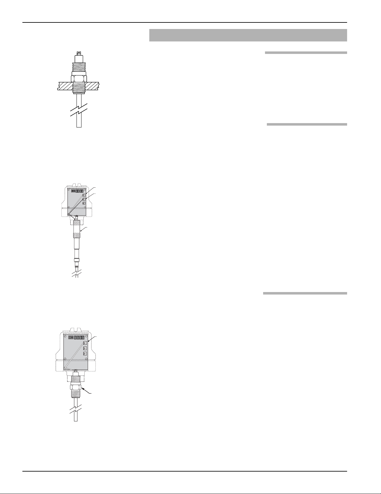
Figure 1
Recommended Horizontal Mounting
Figure 2
Recommended Mounting with Nozzle
Figure 3
Not Recommended
Figure 4
Recommended Horizontal Mounting
Guarded Probe
Figure 5
Recommended Horizontal Mounting
Guarded Probe
Figure 6
Alternate Horizontal Mounting
Page 8
50-608 Kotron Model 811 RF Point Level Sensor
5
1.5 Probe Installation
1.5.1 Installing a Guarded Probe
1. Thread electronics/probe assembly (pre-assembled) into
mounting bushing on tank.
2. Tighten securely (ensure that the wrench is applied
only to the mounting gland). Refer to Figure 8.
3. Proceed to Wiring, Section 1.7, on page 8.
1.5.2 Installing a Standard Probe
Before installing, ensure the:
• Probe has adequate headroom for installation and has
unobstructed entry in the vessel.
• Process temperature, pressure, dielectric, and viscosity are
within the probe specifications for the installation. See
Specifications, Section 2.6, on page 21.
1. Thread probe into mounting bushing on tank.
2. Tighten securely, being certain that the wrench is applied
ONLY to the mounting gland. Refer to Figure 9.
3. Screw the amplifier housing onto the probe. Refer to
Figure 9.
4. Screw housing on the probe until hand tight. Housing
can be wrench tightened to align conduit connection
with conduit.
1.5.3 Installing a Flexible Probe
Caution: Insulated flexible probes are shipped with the cable clamp
and the packing gland nut hand tightened to permit length
adjustment in the field. The cable clamp and packing
gland nut must be tightened before use.The end of a flexible probe MUST be kept taut by attaching the anchor
end at the bottom of the vessel or by using a Magnetrol
supplied probe weight.
Caution: Do not discard the Mylar housing insulator.
Caution: The probe cable must not be in contact with any metallic
surface in its final installation position.
1. Attach the weight or anchor assembly to the end of the
probe. Insert the probe through the vessel’s mounting connection, and feed the cable into the vessel. Do not allow
the probe to scrape against the connection threads.
2. Secure the anchor assembly (if used), to the bottom of
the vessel.
Figure 7
Vertical Mounting
Figure 8
Integral Mount with Guarded Probe
Figure 9
Integral Mount with
Standard Rigid Probe
Mounting
Gland
Probe
(White)
Guard
(Red)
Probe
(White)
1 2 3 4
OPEN
1 2 3 4
OPEN
Lower Probe
Mounting Gland
Page 9
50-608 Kotron Model 811 RF Point Level Sensor
6
Clamp
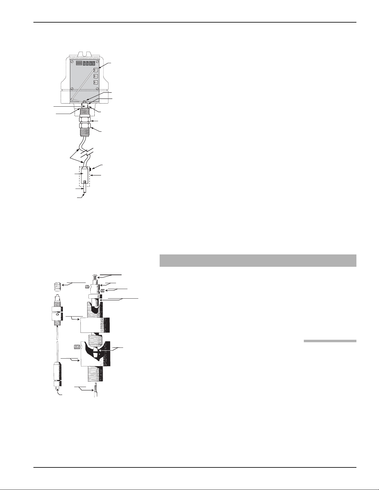
Figure 10
Integral Mount with Flexible Probe
3. Apply thread sealant to the mounting nut. Screw the
mounting nut into the mounting connection until tight.
4. Remove the Mylar housing insulator located over the
clamp. DO NOT DISCARD.
5. Loosen both socket head screws from the clamp. Pull the
clamp and Teflon retaining bushing off of the probe.
6. While holding on to the probe cable, loosen the upper
packing gland nut. DO NOT ALLOW THE PROBE
CABLE TO FALL INTO THE VESSEL.
7. Pull the excess cable up through the packing gland nut
until the cable is taut. Tighten the packing gland nut.
8. Cut the cable 1.35" (34 mm) above the packing gland nut
and strip off 1.25" (32 mm) of insulation.
9. Slide the Teflon retaining bushing onto the cable and seat
it into the packing gland nut. Slide the clamp onto the
cable and seat it against the Teflon retaining bushing.
10. Tighten both socket head screws, on the clamp, to approximately 35 in/lbs of torque. Slip the Mylar insulator over
the clamp.
Caution: Check probe terminal connection carefully to be certain
lug will not short to packing gland or interfere with assembly of amplifier housing to probe.
1.6 Installing a Remote Mount Unit
NOTE: All remote mount units use triaxial cable that is shipped in a
length specified at the time of order. This cable must always
make all 3 connections at the main amplifier. At the probe
head, the cable will always make at least 2 connections.
(PROBE and GROUND). The final connection (GUARD) is only
used with the guarded probe. Cut the guard wire back to the
cable and dress with tape when NOT in use.
1.6.1 Remote Mount with Guarded Probe
1.6.1.1 Electronic Housing
Remote electronic housings are normally shipped from the
factory assembled with a mounting bracket. To install the
electronic housing, proceed as follows. Refer to Figure 11.
1. Install bracket in a location which will isolate unit from
temperatures below -40°F (-40° C) and over +160° F
(+71° C) or vibration/mechanical damage. Unit can be
mounted up to 150 feet (45 m) from probe assembly.
Location should also offer easy access for wiring,
calibration and maintenance.
ECTFE Flexible Probe
Teflon
Retaining
Bushing
Flexible
Termination
Optional Weight
Tank Bracket
Connection
Probe
Probe
1 2 3 4
OPEN
Probe
(White)
Probe Connection Screw
Mylar Housing Insulator
(slips over clamp)
Socket Head
Clamp Screws (2)
Upper Probe
Mounting Gland
Lower Probe
Mounting Gland
Probe Locking
Set Screw
Optional
Mounting
Bracket
(Used w/
Insulated
Probes)
PROBE
MYLAR
INSULATOR
UPPER
MOUNTING
NUT HALF
LOWER
MOUNTING
NUT HALF
PROBE
CABLE
3/8 16 UNC 2B
WIRE SCREW
CLAMP
SET SCREW
CLAMP RETAINING
BUSHING
SEAL
FLARE
Page 10

50-608 Kotron Model 811 RF Point Level Sensor
7
1.6.1.2 Probe Housing Connections
1. Screw probe housing onto the probe.
2. Attach the red guard wire to the slip-on guard connection
on probe. Refer to Figure 10a, Probe Wire Connections.
3. Attach the white probe wire to the probe screw on top of
the probe. Refer to Figure 11.
4. Attach the green ground wire to the green ground screw in
the housing base. Refer to Figure 11.
5. Proceed to Wiring, Section 1.7, on page 8.
1.6.2 Remote Mount with Rigid and Flexible Probes
1.6.2.1 Electronic Housing
Remote electronic housings are normally shipped from the
factory assembled in a mounting bracket. To install the
electronic housing, proceed as follows. Refer to Figure 12.
1. Install bracket in a location that will isolate the unit from
temperatures below -40° F (-40° C) and over +160° F
(+71° C) or vibration/mechanical damage. Unit can be
mounted up to 150 feet (45 m) from probe assembly.
Location should also offer easy access for wiring,
calibration, and maintenance.
1.6.2.2 Probe Housing Connections
1. Screw probe housing onto the probe. Refer to Figure 12.
2. Attach the white probe wire to the probe screw on top of
the probe. Refer to Figure 12.
3. Attach the green ground wire to the green ground screw in
the housing base. Refer to Figure 10a, Probe Wire
Connections and Figure 12.
4. Trim red GUARD wire back to cable end. Insulate with
electrical tape.
Figure 12
Figure 11
Probe
Figure 10a
(White)
PROBE WIRE CONNECTIONS
Guard
(Red)
1 2 3 4
OPEN
Probe (White)
Guard (Red)
Ground (Green)
Connection
Probe
Ground
(Green)
Ground
Screw
Guard
Connection
Mounting
Gland
1 2 3 4
OPEN
Probe (White)
Guard (Red)
Ground (Green)
Ground
Screw
Cut Back
Guard Wire
and Tape
Lower Probe
Mounting Gland
Page 11

50-608 Kotron Model 811 RF Point Level Sensor
8
1.7 Wiring
1.7.1 Probe Wiring
All power and control connections are made at the terminal
strip within the amplifier enclosure, EXCEPT GROUNDING. Power grounding must be made at green ground
screw on the housing base. 16AWG is recommended for
power and control circuits.
NOTE: There are special wiring exceptions for intrinsic safety. Observe
all local electrical codes and proper wiring procedures.
1. Ensure that power source is turned off.
2. Unscrew and remove housing cover.
3. Remove electronic assembly by loosening three screws
in base.
4. Pull power supply and control wires through conduit
connection.
5. Integral Mount Units – pull probe cable through bottom
base connection.
Remote Mount Units – pull triaxial probe cable through
bottom base connection.
6. Loosen securing screw on bottom of shield andopen the
protective cover on the amplifier board.
7. a. Integral Electronics – Attach white probe wire from
probe terminal on circuit board to probe screw on top
of the probe. Attach red Guard wire (if utilized). See
Figure 8 on page 5.
b. Remote Electronics – Attach the white and red leads
from the triaxial cable to appropriate connection on
circuit board. See Figure 12.
8. Ensure wiring is passed through bottom of electronic
assembly bracket.
9. Close and secure protective cover.
10. Slowly lower electronic assembly into housing base while
pushing slack into conduit.
11. Tighten three screws to housing base.
12. Connect electrical green ground wire to green ground
screw located in the base of the housing.
NOTE: If separate I.S ground is required in this application, then I.S.
ground (conventionally, blue #12 wire) should be connected to
the barrier at this time. Refer to NEC and appropriate Agency
guidelines.
Page 12

50-608 Kotron Model 811 RF Point Level Sensor
9
1.7.2 Electrical Wiring
1. Connect power leads to applicable AC or DC terminals as
marked. Refer to Figure 13.
2. a. Connect control circuit leads to relay terminals Refer to
Figure 13. Make sure the load to be controlled is within the relay’s rated capacity.
b. Dress wiring to guard against interference or contact
with cover or circuit board components.
Caution: In hazardous area, do not power the unit until the conduit
is sealed and enclosure cover is screwed down securely.
3. Prevent moisture seepage into housing by installing an
approved seal-drain fitting in the conduit run leading to
the unit.
4. Select operating mode. (Refer to Operating Mode
Selection below for detailed information.) Make sure
the fail-safe switch is in the correct position.
5. Installation is complete. Replace housing cover.
6. Proceed to Calibration, Section 1.8, on next page.
1.7.3 Operating Mode Selection
The Relay Wiring Chart on page 10 is provided to aid
in the proper choice of relay wiring and calibration.
Please note:
1. Equipment controlled by the Model 811 relay is assumed
to be powered from one source, while the 811 unit itself is
assumed to be powered from a different source.
2. There is a fail-safe switch on the 811 unit which may be
set in either a High or Low position. Refer to Figure 15
on next page.
3. Fail means a loss of power to the 811.
4. HL (High Level) means a material level in the tank which
is equal to or above the set point.
5. LL (Low Level) means a material level in the tank which is
equal to or below the set point.
6. a. When the relay coil is de-energized, (LED will be off)
a connection is made between the common (COM)
and normally closed (NC) terminals, and there is no
connection between COM and normally open (NO)
terminals.
b. When the relay coil is energized, (LED will be on)
a connection is made between the COM and
NO terminals, and there is no connection between
COM and NC terminals. Refer to Relay Wiring Chart,
Section 1.7.4, on next page.
Figure 13
COM (DC-)
RELAY LED
HOT (DC+)
GND
(Green
ground
screw
in base)
COM
NO
NC
COM
NO
I.S. BARRIER
NC
Figure 14
Page 13

50-608 Kotron Model 811 RF Point Level Sensor
10
1.7.4 RELAY WIRING CHART
Kotron Material
Fail-safe
Relay
Relay Terminals
Power Level Coil
COM to NC COM to NO
High
HLFS De-energized Closed Open
On
LLFS Energized Open Closed
Low
HLFS Energized Open Closed
LLFS De-energized Closed Open
High
HLFS De-energized Closed Open
Fail
LLFS De-energized Closed Open
Low
HLFS De-energized Closed Open
LLFS De-energized Closed Open
1.8 Calibration — Narrow Differential
Caution: In hazardous areas, do not remove housing cover until
power is disconnected and atmosphere is determined to
be safe. Hazardous environments must be declared safe
by local safety authority.
1.8.1 Set Point Adjustment Alarm
1. Turn on power to the instrument.
2. Remove housing cover.
3. Set point location:
a. Conductive media: The set point is located at the tip of
the probe (with guarded or other uninsulated probes).
Calibration is not required for most conductive liquids.
If the unit does not switch on alarm test, then proceed
to Step 4.
b. Non-conductive media: The set point is located on the
probe at a point determined by the set point adjustment. Minimum probe coverage is 4 inches (100 mm).
Calibration is required. Proceed to Step 4.
4. Adjustments – Refer to Figure 15.
4.1 Dip switch
a. Fail-safe
ON = high level
OFF = low level
b. Time Delay Direction
ON = delay on rising level
OFF = delay on falling level
c. Short Time Delay (0.5 to 7 seconds)
3 ON, 4 OFF
d. Long Time Delay (2 to 120 seconds)
3 OFF, 4 ON
NOTE: Switch positions 3 and 4 cannot be both ON or both OFF. One
must be ON the other OFF or the LED and relay will remain ON.
LONG DELAY TIME DELAY
2 to 120 sec.
SHORT DELAY DIFFERENTIAL
0.5 to 7 sec.
DELAY DIRECTION COARSE
FAIL-SAFE FINE
Figure 15
Page 14

50-608 Kotron Model 811 RF Point Level Sensor
11
4.2 Potentiometers
a. Time Delay
• Allows continuous adjustment of time delay within
limits of DIP switch range chosen
• Clockwise rotation increases delay.
b. Differential
• Allows continuous adjustment of pump or valve
control ON to OFF.
• Clockwise rotation increases differential. Full counterclockwise rotation is the narrowest differential and
is used for alarm applications.
c. Coarse
• Allows continuous adjustment of setpoint over the
entire range of the electronics (0 to 1000 pF).
• Clockwise rotation raises SETPOINT on probe.
d. Fine
• Allows precision adjustment of SETPOINT within
the limits of the COARSE SETPOINT adjusted
initially.
• Clockwise rotation raises SETPOINT on probe.
• This is an extremely fine adjustment. Sometimes it is
necessary to go 1 to 2 turns past the final SETPOINT
to stop relay chatter. A small amount of time delay
(2 turns) can also be used.
5. The LED shows the status of the relay coil.
LED on = relay energized LED off = relay de-energized
6. Initial Settings
a. Turn the COARSE, FINE, DIFFERENTIAL and TIME
DELAY POTENTIOMETERS fully counterclockwise
25 full turns or until a clicking sound is detected.
b. Turn FINE control approximately 12 turns clockwise
to the midpoint.
c. Set the DIP switch positions 3 ON, 4 OFF. (Note that
if DIP switch positions 3 and 4 are both ON the LED
and relay will remain on.)
1.8.2 Low Level Alarm
Fail-safe Low – with no media on the probe:
1. Set DIP switch positions 1 OFF, 2 OFF, 3 ON and
position 4 OFF. LED will be ON.
2. Turn the COARSE control clockwise until the LED
turns OFF.
3. Slowly turn the COARSE control counterclockwise until
the LED is on.
4. Turn the FINE control clockwise until the LED stays OFF.
Page 15

50-608 Kotron Model 811 RF Point Level Sensor
12
1.8.3 Low Level Alarm
Fail-safe Low – with media on the probe:
1. Set DIP switch positions 1 OFF, 2 OFF, 3 ON and
position 4 OFF. LED will be ON.
2. Turn the COARSE control clockwise until the LED
turns OFF.
3. Slowly turn the COARSE control counterclockwise until
the LED is ON.
4. Turn the FINE control clockwise until the LED goes OFF,
then counterclockwise until the LED stays ON.
1.8.4 High Level Alarm
Fail-safe High – with no media on the probe:
1. Set DIP switch positions 1 ON, 2 ON, 3 ON and
position 4 OFF. LED will be OFF.
2. Turn the COARSE control clockwise until the LED
turns ON.
3. Slowly turn the COARSE control counterclockwise until
the LED is OFF.
4. Turn the FINE control clockwise until the LED stays ON.
1.8.5 High Level Alarm
Fail-safe High – with media on the probe:
1. Set DIP switch positions 1 ON, 2 ON, 3 ON and
position 4 OFF. LED will be OFF.
2. Turn the COARSE control clockwise until the LED
turns ON.
3. Slowly turn the COARSE control counterclockwise until
the LED is OFF.
4. Turn the FINE control clockwise until the LED turns
ON, then counterclockwise until the LED stays OFF.
1.8.6 Time Delay
If Time Delay is needed for any reason (e.g., surface waves
causing relay chatter), the following two choices must
be made:
Delay Function
• Delay on FILL (rising level) is DIP switch 2 ON.
• Delay on EMPTY (falling level) is DIP switch 2
OFF.
Delay Duration
• 0.5 to 7 second delay – DIP switch 3 ON, 4 OFF.
• 2 to 120 second delay – DIP switch 3 OFF, 4 ON.
• Clockwise rotation increases duration.
Page 16

50-608 Kotron Model 811 RF Point Level Sensor
13
1.9 Calibration—Wide Differential
1.9.1 Set Point Adjustment Control
1. Turn on power to the instrument.
2. Remove housing cover.
3. Adjustments
3.1 Dip switch
a. Fail-safe
ON = high level
OFF = low level
b. Time Delay Direction
ON = delay on rising level
OFF = delay on falling level
c. Short Time Delay (0.5 to 7 seconds)
3 ON, 4 OFF
d. Long Time Delay (2 to 120 seconds)
3 OFF, 4 ON
NOTE: Switch positions 3 and 4 cannot be both ON or both OFF. One
must be ON the other OFF or the LED and relay will remain ON.
3.2 Potentiometers
a. Time Delay
• Allows continuous adjustment of time delay within
limits of DIP switch range chosen.
• Clockwise rotation increases delay.
b. Differential
• Allows continuous adjustment of pump or valve
control ON to OFF.
• Clockwise rotation increases differential. Full counterclockwise rotation is the narrowest differential and
is used for alarm applications.
c. Coarse
• Allows continuous adjustment of setpoint over entire
range of the electronics (0 to 1000 pF).
• Clockwise rotation raises SETPOINT on probe.
d. Fine
• Allows precision adjustment of SETPOINT within
the limits of the COARSE SETPOINT adjusted
initially.
• Clockwise rotation raises SETPOINT on probe.
Page 17

50-608 Kotron Model 811 RF Point Level Sensor
14
• This is an extremely fine adjustment. Sometimes it is
necessary to go 1 to 2 turns past the final SETPOINT
to stop relay chatter. A small amount of time delay
(2 turns) can also be used.
4. The LED shows the status of the relay coil.
LED on = relay energized.
LED off = relay de-energized
5. Set the Fail-safe Mode Selection.
a. In low level fail-safe (LLFS) mode, the relay is
de-energized on rising level and remains de-energized
until upper differential point is reached.
b. In high level fail-safe (HLFS) mode, the relay is
de-energized on falling level and remains de-energized
until the lower setpoint is reached.
6. DIP switch positions:
a. Low Level Fail-safe
1 OFF, 2 OFF, 3 ON, 4 OFF.
LED will be ON.
b. High Level Fail-safe
1 ON, 2 ON, 3 ON, 4 OFF.
LED will be OFF.
7. Verify process level is at desired low control point.
8. COARSE adjustment
a. Low Level Fail-safe
Turn COARSE control clockwise until LED turns OFF.
Turn COARSE control counter clockwise until the
LED is ON.
Slowly turn COARSE control clockwise until LED is
OFF. Low control point is now calibrated.
b. High Level Fail-safe
Turn COARSE control clockwise until LED turns ON.
Turn COARSE control counterclockwise until LED
is OFF.
Slowly turn COARSE control counterclockwise until
LED is ON. Low control point is now calibrated.
NOTE: FINE control can be used during wide differential calibration,
but is usually not needed.
9. Prior to raising level to desired high control point, turn
Differential control 25 turns clockwise or until clicking
sound is heard.
10. Raise level to desired high control point.
Page 18

50-608 Kotron Model 811 RF Point Level Sensor
15
11. Differential control
a. Low Level Fail-safe
Slowly turn Differential control counterclockwise
until the LED turns ON. The wide differential point
is calibrated.
b. High Level Fail-safe
Slowly turn Differential control counterclockwise
until the LED turns OFF. The wide differential point
is calibrated.
1.9.2 Time Delay
If Time Delay is needed for any reason (e.g., surface waves
causing relay chatter), the following two choices must
be made:
Delay Function
• Delay on FILL (rising level) is DIP switch 2 ON.
• Delay on EMPTY (falling level) is DIP switch 2
OFF.
Delay Duration
• 0.5 to 7 second delay – DIP switch 3 ON, 4 OFF.
• 2 to 120 second delay – DIP switch 3 OFF, 4 ON.
• Clockwise rotation increases duration.
LONG DELAY TIME DELAY
2 to 120 sec.
SHORT DELAY DIFFERENTIAL
0.5 to 7 sec.
DELAY DIRECTION COARSE
FAIL-SAFE FINE
Figure 16
Page 19

50-608 Kotron Model 811 RF Point Level Sensor
16
2.0 Reference Information
This section presents an overview of the operation of
the Kotron Model 811 RF Point Level Sensor, information
on troubleshooting common problems, intrinsic safety
information, physical, functional and performance
specifications, listings of agency approvals, and a list
of recommended parts
2.1 Description
The Kotron Model 811 RF Point Level Sensor can be
utilized in liquid or bulk material applications. There are
no moving parts in contact with the medium.
2.2 Theory of Operation
As the medium in contact with the probe rises and falls,
the amount of capacitance develops between the probe and
the ground changes. This change in capacitance is converted into level. When the level (capacitance) reaches a
desired amount, the relay will change state.
2.3 Troubleshooting
2.3.1 No Signal with Level Change
1. Check power and control circuit wiring.
2. Check DIP switch positions.
3. Check Calibration.
4. Check for proper ground reference particularly in
non-metal tanks.
2.3.2 Probe
Caution: When an insulated probe is used in a hazardous and/or
abrasive medium, the probe should be inspected periodically for nicks, cuts or abrasions which may ruin the
integrity of the insulation. In the event that wear is found –
replace the probe or consult the factory for further instructions. This procedure is critical in vessels containing
hazardous media.
To check for a malfunctioning sensing probe:
1. Remove the white probe lead from the sensing probe and
isolate it from the ground.
2. Connect an ohmmeter between the sensing probe terminal
and ground. (i.e., stainless steel probe nut or housing base)
Page 20

50-608 Kotron Model 811 RF Point Level Sensor
17
3. Measure the resistance between the probe and ground
using the highest resistance scale available. If the resistance
measures 10 Megohm to infinity and is stable, the probe
is operating correctly. If the resistance measures less than
10 Megohm and/or is unstable, there may be a problem
with the probe.
2.3.3 Switch Chatter
1. Check for turbulence. If turbulence is present, increase
time delay until appropriate.
2. Check for proper power supply voltage.
3. Check for proper ground reference.
NOTE: If the application uses an insulated probe in a conductive
medium, it is helpful to have the medium at its highest possible
level. This aids in the detection of cuts or nicks in the insulation.
4. Inspect the malfunctioning probe for a cut in the insulating
sheath or looseness in the seal at the probe mounting nut.
5. Inspect the probe for a coating or build-up of conductive
medium.
6. Measure the resistance between the probe and ground
using the highest resistance scale available. If the resistance
measures 10 Megohm to infinity and is stable, the probe
is operating correctly. If the resistance measures less than
10 Megohm and/or is unstable, there may be a problem
with the probe.
7. If probe test is working properly, check for insufficient
ground, loose or broken wiring, including the white probe
wire. Also check continuity between probe mounting nut
and metal tank. There should be continuity (zero resistance). If there is resistance, check for excessive teflon tape
used on the probe threads.
NOTE: If the above suggestions prove unsuccessful, consult factory.
Page 21

50-608 Kotron Model 811 RF Point Level Sensor
18
Agency Approved Model Protection Method Area Classification
FM 811-1X05-E0X Explosion Proof Explosion proof with intrinsically safe probe circuit
811-1X06-E0X Class I, Div. 1, Groups C & D
with probe models: Class II, Div. 1, Groups E, F, & G
041-5XXX-XXX and NEMA 4X
8XX-XXX-XXX
811-1X06-E0X Intrinsically Safe Remote probe:
(Remote) Class I, Groups A, B, C, & D
with probe models: Class II, Div. 1, Groups E, F, & G
041-5XXX-XXX and Class III,
8XX-XXX-XXX NEMA 4X
CSA 811-1X05-E0X Explosion Proof Explosion proof with intrinsically safe probe circuit
811-1X06-E0X Class I, Div. 1, Groups C & D
with probe models: Class II, Div. 1, Groups E, F, & G
041-5XXX-XXX and (Bare probes not approved for Groups E & F)
8XX-XXX-XXX TYPE 4X
811-1X06-E0X Intrinsically Safe Remote probe:
(Remote) Class I, Div. 1, Groups A, B, C, & D
with probe models: Class II, Div. 1, Groups E, F, & G
041-5XXX-XXX and (Bare probes are not approved for Groups E & F)
8XX-XXX-XXX Class III
TYPE 4X
These units have been tested to EN 50081-2
and EN 50082-2 and are in compliance with
the EMC Directive 89/336/EEC.
2.4 Agency Approvals
Page 22

50-608 Kotron Model 811 RF Point Level Sensor
19
2.4.1 Agency Specifications – Intrinsically Safe Installation
2.4.2 Agency Specifications – Explosion Proof Installation
Page 23

50-608 Kotron Model 811 RF Point Level Sensor
20
2.5 Parts
2.5.1 Replacement Parts
Item Description Part Number
Complete electronic assembly: Z30-9102-001 120 VAC
Items 1 and 2 (listed below) Z30-9102-002 240 VAC
Mounting bracket Z30-9102-003 24 VDC
Z30-9102-004 12 VDC
Power supply board* (integral or remote)
Z30-4502-001 120 VAC
Z30-4502-002 240 VAC*
Z30-4502-003 12 VDC
Z30-4502-004 24 VDC
I.S. amplifier board* (integral or remote) Z30-4506-001
Electronics cover (integral or remote)
Aluminum 002-6204-600
316 stainless steel 002-6204-605
Electronics o-ring (integral or remote) 012-2101-345
Electronics base (integral or remote)
Aluminum, dual 3⁄4" NPT conduit connection 004-9182-003
316 stainless steel, single 3⁄4" NPT conduit connection 004-9140-002
Remote probe cover
Aluminum 004-9105-001
316 stainless steel 004-9142-001
Remote housing o-ring 012-2101-345
Remote housing base
Aluminum, single
3
⁄4" NPT conduit connection 004-9104-001
316 stainless steel, single 3⁄4" NPT conduit connection 004-9140-002
Remote triaxial cable (standard)** 037-3180-XXX
Remote triaxial cable (high temperature)** 037-3184-XXX
Remote mounting bracket
1
⁄2" NPT conduit connection 036-3805-001
3
⁄4" NPT conduit connection 036-3805-003
Guarded Probe 18" (457 mm) (integral or remote) 8AD-AA1A-018
Guarded Probe 36" (914 mm) (integral or remote) 8AD-AA1A-036
* Refer to ESD handling procedure on page 1.
** Specify remote cable by exact length, 10 to 150 feet (3 to 45 M).
Standard (+176°F/+80°C) 37-3180-XXX (length in feet).
High Temp. (+392°F/ +200°C) 37-3184-XXX (length in feet).
Figure 17
Remote Mount with Guarded Probe
1
2
3
4
5
6
7
8
9
10
11
12
13
6
8
12
13
3
7
2
5
1
4
11
9
10
Page 24

50-608 Kotron Model 811 RF Point Level Sensor
21
Supply Voltage 120 VAC 50–60 Hz (+10%, -15%)
240 VAC 50–60 Hz (+10%, -15%)
24 VDC (±10%)
12 VDC (±10%)
Power Consumption 120 or 240 VAC Less than 5 volt-amps
12 or 24 VDC 1 watt maximum
Zero Range 0 pF minimum to 1000 pF maximum
Adjustable Differential 0.5 pF to 700 pF
Output relays DPDT with gold flash contacts AC 10 amp @ 120/240 VAC resistive
DPDT with gold flash contacts DC 10 amp @ 30 VDC resistive
DPDT with gold flash contacts DC 0.5 amp @ 125 VDC resistive
Response time 100 milliseconds
Repeatability Better than 1.0%
Ambient Temperature Electronics -40° to +160° F (-40° to +70° C)
Operating Process
Pressure/Temperature Dependent upon probe selected — See probe brochure 50-125
Temperature Coefficient of
Set Point -40° to +160° F (-40° to +70° C) ± .01% per degree F of setpoint
(± .018% per degree C of setpoint)
Electrostatic Discharge Protection per IEC spec. 801-2
2.6 Specifications
2.6.1 Functional
Page 25

50-608 Kotron Model 811 RF Point Level Sensor
22
NOTES:
Allow 6 in. (152 mm) overhead clearance for removal of NEMA 4X/7/9 cover.
Probe/Amplifier Connecting Cable to be triaxial. Magnetrol
P/N 037-3180-XXX standard or P/N 037-3184-XXX high temperature.
Integral Mount with Guarded Probe Remote Mount with Guarded Probe
Integral Mount with Standard Rigid Probe Remote Mount with Standard Rigid Probe
Integral Mount with Flexible Probe Remote Mount with Flexible Probe
Standard process connection is
3
⁄4" NPT. Consult probe brochure
(50-125) for flange and other probe connections.
2.6.2 Physical
NEMA 4X/7/9
➀
9.33 (247)
3/4" NPT
Conduit
Connection
Rotation Clearance:
2.63 (66)
3/4" NPT
Conduit
Connection
(Plugged)
Optional
Mounting
Flange
3/4" NPT
Thread
.375 (10)
2 Holes
.38 (10) Dia.
2.00
(51)
NEMA 4X/7/9
➀
7.75 (197)
3/4" NPT
Conduit
Connection
2.37
(60)
3.00
(76)
3.50
(89)
3.75
(95)
➁
Rotation Clearance:
2.63 (66)
3/4" NPT
Connection
3/4" NPT
Conduit
Connection
(Plugged)
1/2" NPT (opt.)
3/4" NPT (std.)
Transducer/Amplifier
Cable Connection
Conduit
4.11
(104)
3/4" NPT
Thread
Rotation Clearance:
2.63 (66)
3/4" NPT
Conduit
Connection
3/4" NPT
Conduit
Connection
(Plugged)
1/2" NPT (opt.)
3/4" NPT (std.)
Transducer/Amplifier
Cable Connection
NEMA 4X/7/9
➀
8.45 (215)
3/4" NPT
Conduit
Connection
Rotation Clearance:
2.63 (66)
3/4" NPT
Conduit
Connection
(Plugged)
Optional
Mounting
Flange
.38 (10) Dia.
➂
2 Holes
2.00
(51)
NEMA 4X/7/9
➀
7.75 (197)
3/4" NPT
Conduit
Connection
2.37
(60)
3.50
(89)
3.00
(76)
3.75
(95)
➁
Rotation Clearance:
3.00 (76)
6.86
(174)
18" (457)
or
36" (914)
.375 (10)
Rotation Clearance
3.00 (76)
5.98
(152)
➂
Rotation Clearance:
2.63 (66)
3/4" NPT
Conduit
Connection
3/4" NPT
Conduit
Connection
(Plugged)
1/2" NPT (opt.)
3/4" NPT (std.)
Transducer/Amplifier
Cable Connection
3/4" NPT
Thread
Optional
Anchor
Assembly
032-8814-001
(124)
(140)
4.87
5.50
1.32
(34)
NEMA 4X/7/9
➀
9.89 (251)
3/4" NPT
Conduit
Connection
Optional
Anchor
Assembly
(127)
4.87
(124)
5.00
1.32
(34)
.1250 (3)
.1875 (5)
.2500 (6)
2.95
(75)
79
(19)
➂
Optional
Weight
Rotation Clearance:
2.63 (66)
3/4" NPT
Conduit
Connection
(Plugged)
Optional
Mounting
Flange
.38 (10) Dia.
2 Holes
2.00
(51)
NEMA 4X/7/9
➀
7.75 (197)
3/4" NPT
Conduit
Connection
2.37
(60)
3.50
(89)
3.00
(76)
3.75
(95)
➁
.50 (13)
.625 (16)
Rotation Clearance
3.00 (76)
7.42
(188)
➂
.1250 (3)
.1875 (5)
.2500 (6)
2.95
(75)
Optional
79
Weight
(19)
P/N 004-4355-001
Page 26

50-608 Kotron Model 811 RF Point Level Sensor
23
3.0 Model Numbers
811 10 0
0 120 VAC
1 240 VAC
2 24 VDC
3 12 VDC
INPUT POWER
811 Kotron RF Capacitance Level Switch
BASIC MODEL — FM & CSA APPROVED MODELS
5 Integral
6 Remote
E
NEMA 4X/7/9 Groups C & D, aluminum,
3
⁄4" NPT dual conduit
Y
NEMA 4X/7/9 Groups C & D, stainless steel,
3
⁄4" NPT single conduit
HOUSING
MOUNTING
PROBE
0 Probe ordered separately
1 18" (455 mm) guarded probe
2 36" (915 mm) guarded probe
Page 27

50-608 Kotron Model 811 RF Point Level Sensor
24
NOTES:
Page 28

BULLETIN: 50-608.6
EFFECTIVE: June 2004
SUPERSEDES: June 2002
Service Policy
Owners of Magnetrol/STI controls may request the return
of a control or any part of a control for complete rebuilding or replacement. They will be rebuilt or replaced
promptly. Controls returned under our service policy
must be returned by Prepaid transportation.
Magnetrol/STI will repair or replace the control at no cost
to the purchaser (or owner) other than transportation if:
1. Returned within the warranty period; and
2. The factory inspection finds the cause of the claim to
be covered under the warranty.
If the trouble is the result of conditions beyond our control; or, is NOT covered by the warranty, there will be
charges for labor and the parts required to rebuild or
replace the equipment.
In some cases it may be expedient to ship replacement
parts; or, in extreme cases a complete new control, to
replace the original equipment before it is returned. If this
is desired, notify the factory of both the model and serial
numbers of the control to be replaced. In such cases, credit
for the materials returned will be determined on the basis
of the applicability of our warranty.
No claims for misapplication, labor, direct or consequential damage will be allowed.
Return Material Procedure
So that we may efficiently process any materials that are
returned, it is essential that a “Return Material
Authorization” (RMA) number be obtained from the factory, prior to the material's return. This is available
through Magnetrol’s local representative or by contacting
the factory. Please supply the following information:
1. Company Name
2. Description of Material
3. Serial Number
4. Reason for Return
5. Application
Any unit that was used in a process must be properly
cleaned in accordance with OSHA standards, before it is
returned to the factory.
A Material Safety Data Sheet (MSDS) must accompany
material that was used in any media.
All shipments returned to the factory must be by prepaid
transportation.
All replacements will be shipped F.O.B. factory.
NOTE: See Electrostatic Discharge Handling Procedure
on page 1.
ASSURED QUALITY & SERVICE COST LESS
5300 Belmont Road • Downers Grove, Illinois 60515-4499 • 630-969-4000 • Fax 630-969-9489 • www.magnetrol.com
145 Jardin Drive, Units 1 & 2 • Concord, Ontario Canada L4K 1X7 • 905-738-9600 • Fax 905-738-1306
Heikensstraat 6 • B 9240 Zele, Belgium • 052 45.11.11 • Fax 052 45.09.93
Regent Business Ctr., Jubilee Rd. • Burgess Hill, Sussex RH15 9TL U.K. • 01444-871313 • Fax 01444-871317
5300 Belmont Road • Downers Grove, Illinois 60515-4499 • 630-969-4028 • Fax 630-969-9489 • www.sticontrols.com
Copyright © 2006 Magnetrol International, Incorporated. All rights reserved. Printed in the USA.
Magnetrol and Magnetrol logotype are registered trademarks of Magnetrol International.
STI and STI logotype are registered trademarks of Magnetrol International.
Performance specifications are effective with date of issue and are subject to change without notice.
 Loading...