

Page 1
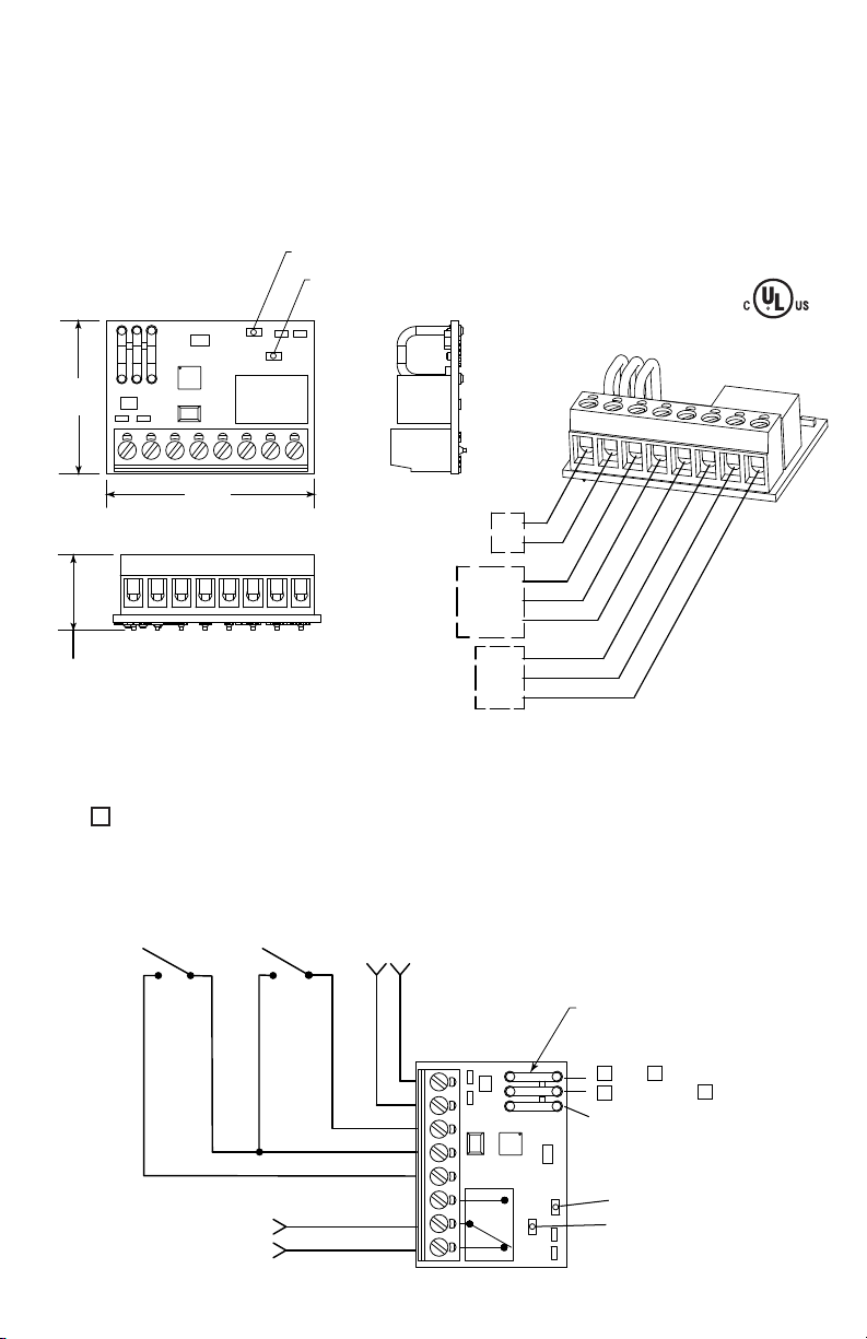
NOTE:
RELAY ACTIVE LED RED
POWER LED GREEN
1.28 in.
33mm
1.74 in.
44mm
.632 in.
16mm
+
-
*POWER IN
12 - 24 VAC/VDC, 18 mA
TIMER
CONTROL
FORM “C”
DRY CONTACTS
3A, 30VDC
RESET
INPUT COM
T
RIGGER
N.C.
COM
N.O.
+
-
x
TIMER START
SWITCH
TIMER OVERRIDE
RESET (OPTIONAL)
*POWER IN
12-24 VAC/VDC
TO MAGNETIC LOCK
(FAIL SAFE MODE)
JUMPERS
15 SEC
RELAY MODE JUMPER
30 SEC
45 SEC
LATCH
ILLUMINATING GREEN
ILLUMINATING RED
SHOWN: POWER ON
NORMAL CONDITION
xx
x
STI LATCHING/TIMER MODEL LT-1UL
It is important to read, understand and follow all instructions provided with this product. It is the installer’s responsibility to
comply with NFPA 70, 72 & 101, NEC, mounting specifications according to ADA and other applicable codes. This product
is not to be used in place of panic hardware. To avoid electrical shock, DO NOT attempt to install this product when power
is on. After installation and testing are complete, provide a copy of this manual to all personnel responsible for testing and
maintenance of this product.
*For access control installations, power for the LT-1UL Timer must be supplied by a power source Listed to UL294. When
used for access control, this device shall be used a part of an access controlled egress door system. It is up to the local
AHJ to allow use of this device in place of an automatic sensor. For higher security installations, lower time limits should
be used.
RELAY MODE
N.O. - Relay N.O. -switches with power to circuit - Fail Safe (default)
N.C. - Relay is in same state as with no power to circuit - Fail Secure (cut jumper)
TO CHANGE TIMER SETTINGS (default = 15 seconds): Cut jumpers with “X”, do not cut jumpers
with “ “.
If the trigger is activated during a timing cycle, the timer is restarted.
NOTE: To ensure jumpers do not reattach or short to other components, cut jumper off completely
flush to PCB.
Page 2
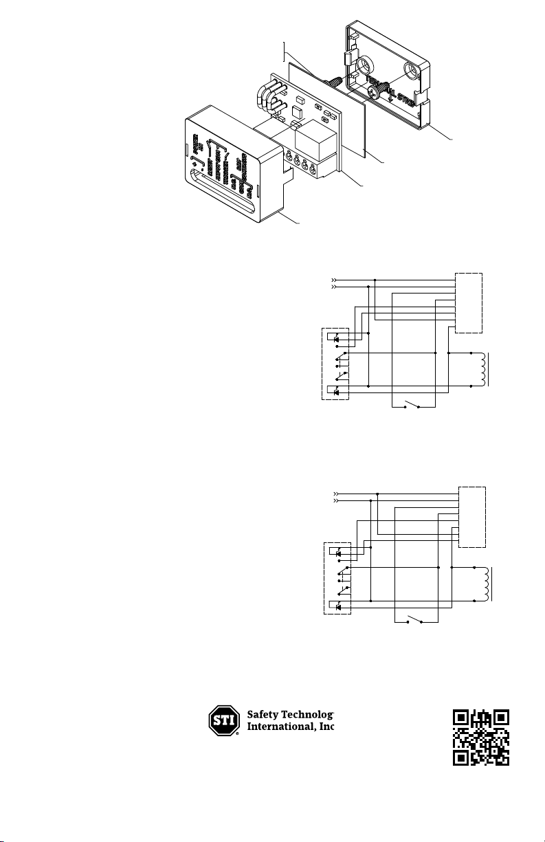
FAIL SAFE MODE
WIRING DIAGRAM
12-24 VAC/VDC
UB-1/UB-2
BUTTON LED
CONTACT SET 1
CONTACT SET 2
MESSAGE LED
NO
C
OM
N
O
NC
NC
C
OM
+
–
R
ST
I
NPUT COM
TRIG
R
ELAY NC
RELAY COM
RELAY NO
LT-1
DOOR
LOCK
RESET SWITCH
(OPTIONAL EXCEPT ON
LATCH TIMER SETTING)
FAIL SECURE MODE
WIRING DIAGRAM
12-24 VAC/VDC
UB-1/UB-2
BUTTON LED
CONTACT SET 1
CONTACT SET 2
MESSAGE LED
NO
COM
NO
NC
NC
COM
+
–
RST
INPUT COM
TRIG
RELAY NC
RELAY COM
RELAY NO
LT-1
DOOR
LOCK
RESET SWITCH
(OPTIONAL EXCEPT ON
LATCH TIMER SETTING)
1
9082 #6 - 32 x 5/16”
PHILLIPS PAN HEAD SCREW
(2) PROVIDED
CASE BASE
C
ASE TOP
LT-1PCB
ELECTRONIC INSULATION PAPER
INSTRUCTIONS FOR MOUNTING
1. Locate suitable mounting position
in a listed gang box.
2. Using case base as a template,
mark and drill (2) 7/64” holes.
3. Attach case base with 2 thread
forming screws (included).
4. Install insulation paper.
5. Snap circuit board into place with
terminal strip toward case edge
with arrow.
6. Snap on case top.
7. Wire devices.
CONTACT RATINGS
When used with UB-1/LTUL & UB-2/LTUL Form “C”
contacts are rated maximum 30 VDC 3A.
SS-2XX4/LTUL Form “C” contacts are rated
maximum 30 VDC 3A.
SS-2XX5/LTUL Form “C” contacts are rated
maximum 30 VDC 3A.
SS-2XX7/LTUL Form “C” contacts are rated
maximum 30 VDC 3A.
WARRANTY
One year guarantee on electro mechanical and electronic
components.
Electronic warranty form at www.sti-usa.com/wc14.
Printed in USA LT-1PCB 05/11
Phone: 248-673-9898 • Toll Free: 800-888-4784 • Fax: 248-673-1246
Waterford, Michigan 48327-1209
2306 Airport Road
www.sti-usa.com
 Loading...