

Page 1
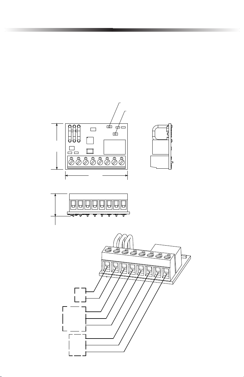
STI LATCHING/TIMER MODEL LT-1
RELAY ACTIVE LED RED
POWER LED GREEN
1.28 in.
33mm
1.74 in.
44mm
.632 in.
16mm
+
-
*POWER IN
12 - 24 VAC/VDC, 18 mA
TIMER
CONTROL
FORM “C”
DRY CONTACTS
3A, 30VDC
RESET
INPUT COM
TRIGGER
N.C.
COM
N.O.
NOTE:
It is important to read, understand and follow all instructions provided with this
product. It is the installer’s responsibility to comply with NFPA 70, 72 & 101, NEC,
mounting specifications according to ADA and other applicable codes. This product is
not to be used in place of panic hardware. To avoid electrical shock, DO NOT attempt
to install this product when power is on. After installation and testing are complete,
provide a copy of this manual to all personnel responsible for testing and maintenance
of this product.
Page 2
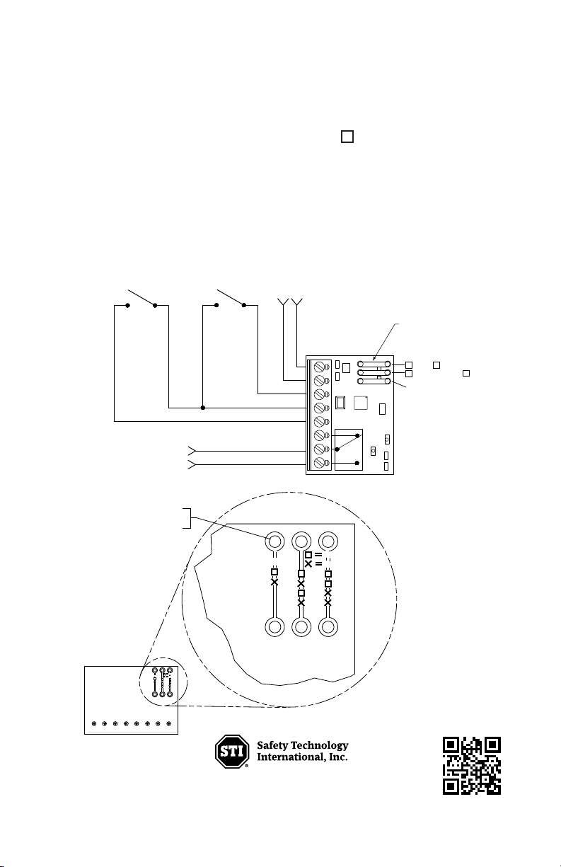
RELAY MODE
+-
x
x
x
x
TIMER START
S
WITCH
TIMER OVERRIDE
RESET (OPTIONAL)
*POWER IN
12-24 VAC/VDC,15mA
TO MAGNETIC LOCK
(FAIL SAFE MODE)
JUMPERS
15 SEC
RELAY MODE JUMPER
30 SEC
45 SEC
LATCH
IF TRACES ARE INADVERTENTLY CUT,
SOLDER JUMPER WIRES USING
APPROPRIATE HOLES.
RELAY MODE
N.O.
N.C.
NO CUT
CUT
15s
30s
45s
Ltch
RelayNORelay
COM
RelayNCTrig Input
Com
Reset Power Input
+
-
12 to 24 Volts
AC or DC
MODEL LT-1
RELAY MODE
N.O.
N.C.
NO CUT
CUT
15s
30s
45s
Ltch
N.O. - Relay switches with power to circuit - Fail Safe
N.C. - Relay is in same state as with no power to circuit - Fail Secure
TO CHANGE TIMER SETTINGS
Cut jumpers with “X”, do not cut jumpers with “ “.
Default timer setting is 15 seconds.
If the trigger is activated during a timing cycle, the timer is restarted.
NOTE: To ensure jumpers do not reattach or short to other components, cut
jumper off completely flush to PCB.
Electronic warranty form at www.sti-usa.com/wc14.
Printed in USA LT-1PCB 11/10
Waterford, Michigan 48327-1209
2306 Airport Road
Phone: 248-673-9898 • Toll Free: 800-888-4784 • Fax: 248-673-1246
www.sti-usa.com
 Loading...