

Page 1
1
Assembly Instructions
Solar collectors FKA 200/240/270
console installation
Page 2
2
Table of contents
Contents Page
Please read these instructions carefully before beginning the assembly.
Observe the warnings indicated by this sign.
They warn of dangers or possibly erroneous actions, which may result in the invalidation of the warranty.
The collectors FKA 200, FKA 240 and FKA 270 are monitored according to the CEN-Keymark program rules
Solarthermal Products and are certified with the registration numbers 011-7S1910 ... 1915 F.
The copyright of this instruction incl. graphical material remains in the property of the STI GmbH. The instruction can
only be duplicated completely or in parts with written authorisation of the STI GmbH. Subject to technical changes and
misprints.
The STI GmbH is obliged to take back with the environmental label RAL-UZ-73 for solar collectors ( „Blauer Engel“)
labeled products, and to consign it to recycling.
Safety regulations, instructions and guidelines 3
Product description 5
Hydraulic connections 7
Collector field dimensions 8
bottom support dimensions 9
Assembly bottom support on concrete block 11
Assembly bottom support with fixed dowel pin 12
Assembly collectors 13
Temperature sensor 15
Spacing roof hooks 16
Assembly base console on roof profile 17
Assembly roof-tile clamps 18
Assembly roof-tile clamps with lead 20
Assembly plain tile clamps without lead 22
Assembly plain tile clamps with lead 23
Assembly roof-tile clamp corrugated 25
Assembly mounting profiles/console 26
Wall console dimensions 27
Assembly wall console 28
Temperature sensor 31
Arrangement hydraulic connections 32
Hydraulic connection with manifold 33
Overview hydraulic connections / accessories 34
Assembly distance metal sheets 35
Pipe dimensions of the connecting pipe 36
Initial operation 38
Appendix 43
Page 3
3
Safety regulations, instructions
and guidelines
Engineer standards and guidelines
• VBG 4 Unfallverhütungsvorschriften Elektrische
Anlagen und Betriebsmittel
• VBG 37 Unfallverhütungsvorschrift Bauarbeiten
• VBG 74 Leitern und Tritte
• ZVDH, Regelwerk (Stand Juni 2001)
• LBO’s Landesbauordnungen der Bundesländer
• DIN 18299 Allgemeine Regelung für Bauarbeiten
jeder Art
• DIN 18334 Zimmer- und Holzbauarbeiten
• DIN 18338 Dachdeckungs- und
Dachabdichtungsarbeiten
• DIN 18339 Klempnerarbeiten
• DIN 18351 Fassadenarbeiten
• DIN 18360 Metallbauarbeiten, Schlosserarbeiten
• DIN 18381 Gas-, Wasser- und Abwasser installationsanlagen
• DIN 18451 Gerüstarbeiten
• DIN 1055 Lastenannahme für Bauten Teil 1-5
• DIN 1988 Teil 1-8 Technische Regeln für die
Trinkwasserinstallation
• DIN 4708 Teil 3 Zentrale Brauchwasser-
erwärmungsanlagen
• DIN 4102 Brandverhalten von Baustoffen und
Bauteilen
• DIN 4109 Schallschutz im Hochbau
• HeizAnlVO Heizungsanlagenverordnung
• ZVH - Richtlinie 11.01 Einbindung solartechnischer
Anlagen in die Hauswärmeversorgung
• TRD 802 Dampfkessel der Gruppe III
• TRD 402 Ausrüstung von Dampfkesselanlagen mit
Heißwassererzeugern der Gruppe IV
• ENV 1991-2-3- 4 Grundlagen der Tragwerksplanung
und Einwirkung auf Tragwerke – Schneelasten und
Windlasten
• DIN EN 516 Einrichtungen zum Betreten des Daches
• EN 517 Sicherheitsdachhaken
• DIN 4751 Teil 1: Wasserheizungsanlagen:
Offene und geschlossene physikalisch
abgesichterte Wäremeerzeugungsanlagen bis 120°C
- Sicherheitstechnische Ausrüstung
Teil 2: Wasserheizungsanlagen: Geschlossene,
thermostatisch abgesicherte Wärmeerzeugungs anlagen mit Vorlauftemperaturen bis 120°C Sicherheitstechnische Ausrüstung
Teil 3: Wasserheizungsanlagen: Geschlossene,
thermostatisch abgesichter te
Wärmeerzeugungsanlagen mit 50 kW
Nennwärmeleistung mit Zwangumlauf Wärmeerzeugern und Vorlauftemperaturen bis 95°C
- Sicherheitstechnische Ausrüstung
• DIN 4753 Teil 1 Wassererwärmer und
Wassererwärmungsanlagen für Trink- und
Betriebswasser;Anforderungen, Kennzeichnung,
Ausrüstung und Prüfung
• DIN 4757 Teil 1: Sonnenheizungsanlagen mit Wasser
und Wassergemischen als Wärmeträger;
Anforderungen an die Sicherheitstechnische
Ausrüstung
Teil 2: Sonnenheizungsanlagen mit organischen Wärmeträgern;
Anforderungen an die sicherheitstechnische Ausrüstung
• DIN VDE 0100-510 Errichten von Starkstromanlagen mit
Nennspannungen bis 1000 V; Allgemeine Bestimmungen
• DIN VDE 0100-725 Errichten von Starkstromanlagen mit
Nennspannungen bis 1000 V; Hilfsstromkreise
• DIN VDE 0100-737 Errichten von Niederspannungsanlagen -
Feuchte und nasse Bereiche und Räume und Anlagen im
Freien
• DIN VDE 0105-100 Betrieb von elektrischen Anlagen
• DIN VDE 0185-1, DIN 57185-1 Blitzschutzanlage, Allgemeines
für das Errichten
• DIN VDE 0190 Einbeziehung von Gas- und Wasserleitungen in
den Hauptpotentialausgleich
• VDE 0855-1, DIN 57855-1 Errichtung und Betrieb (Erdung) von
Antennenanlagen
Connection of solar thermal systems
• DIN EN 12976: Thermische Solaranlagen und ihre Bauteile
(vorgefertigte Anlagen)
• DIN EN 12977: Thermische Solaranlagen und ihre Bauteile
(kundenspezifisch gefertigte Anlagen)
• DIN 1988: Technische Regeln für Trinkwasser-Installation
Notes before starting assembly
The installation and initial operation must be carried out by an expert
who is responsible for the correct installation and operation.
Before installing and putting the collectors into service, please inform
yourself about the local engineer standards and regulations.
Components of the collectors can reach temperatures over 200 °C,
there is a danger of burning and scalding!
Please check whether there are any load sources in the area of the
collector field that may produce chemically aggressive medium.
In condensate dissolved acids and bases can cause permanent
damage to the collector components.
Throughout the installation of a solar collector you directly
intervene into an existing roof cladding. Different roof coverings
such as tile, shingles or slate require as security against the
ingress of moisture due to rain or snow additional measures (eg
sarkings) - especially in case of extended and occupied top floors
or in case of too less roof pitch (concerning the covering).
Page 4
4
Safety regulations, instructions
and guidelines
The substructure as well as its connections to the
building have to be checked on site according to the local
regulations.
The collectors have to be mounted in an angle of at least
20° to max. 70°.
Recommended heat transfer medium is a mixture of glycol
and water, e.g. Tyfocor L or similar The collectors may
never be operated or tested under pressure with water.
To protect the system of overheating during standstill and
accelerated glycole-aging a self-draining system (e.g. STI
Drain Master or Drain Box) is recommended.
It is absolutely necessary to pay attention, that the back flow
temperature is never lower than the ambient temperature. If
necessary, take appropriate action (e.g. increase back flow
temperature to at least 30°C).
Lightning protection
Note country-specific legislation!
Throughout the installation of metal fastening, a check is
needed by an authorized qualified electrician.
The metallic pipes of the solar circle are connected via
a copper pipe of at least 16 mm² with the earth circuit
connector.
Please ensure sufficient ventilation for each assembly
method. Do not close the ventilation openings. Especially
in case of roof-integrated assembly, the ventilation of the
collector is definitely necessary. Appropriate ventilation
hoods are available from the supplier. Pay attention to the
regulations of the ZVDH (Germany), SVDW (Switzerland)
as well as different local regulations concerning the ventilation. If necessary, consult an expert.
Responsibilites
The constructor of the installation is responsible for the integration of the installation according to regulations and for
compliance with the safety regualtions.
The operator of the installation is responsible for an operation of the installation according to regulations and for
consultation of experts in case of problems.
This instruction is not subjected to the control of a service of modifications. It does not absolve the manufacturer and operator of the
installation of his responsibilities to install and operate all parts of
the installation according to utmost professional knowledge. The
manufacturer of the installation is responsible to observe and keep
all appropriate regulations and instructions.
Statics
Before beginning the assembly it is vital to test the roof or
substructure on site to sufficient load-carrying capacity.
Pay increased attention to the possible durability of the screw
fittings to fasten the collectors as well as to the quality of the substructure.
According to DIN 1055 part 4 and 5 or rather according to the local
engineer standards it is necessary to check on site the whole system construction, especially in snowy regions (note: 1 m² powder
snow ~ 60 kg / 1 m² wet snow ~ 200 kg) as well as in regions with
high wind speed. Before starting the assembly all aspects that
may lead to incorrect load of the whole construction have to be
considered!
Install the collectors the way that backlog of snow (e.g. due to
snow guards or other obstacles) is not possible.
In case of correct assembly snow loads (pressure loads) up to 2
kN/m² and wind loads (suction loads) up to 1 kN/m² acting on the
collector are permitted.
For transport and stocking
Never abandon the delivered collectors unprotected at the building
site. Never lay down the collectors onto a rough surface with overhanging pieces like stones, timbers, etc.
Stock the collectors always upright leaning against a solid surface.
The rigidity of the collectors is limited. During transport to the building site always ensure a torsion-free transport type. In case of an
elevated intermediate storage make sure that the collectors are
protected against sliding down.
Page 5
5
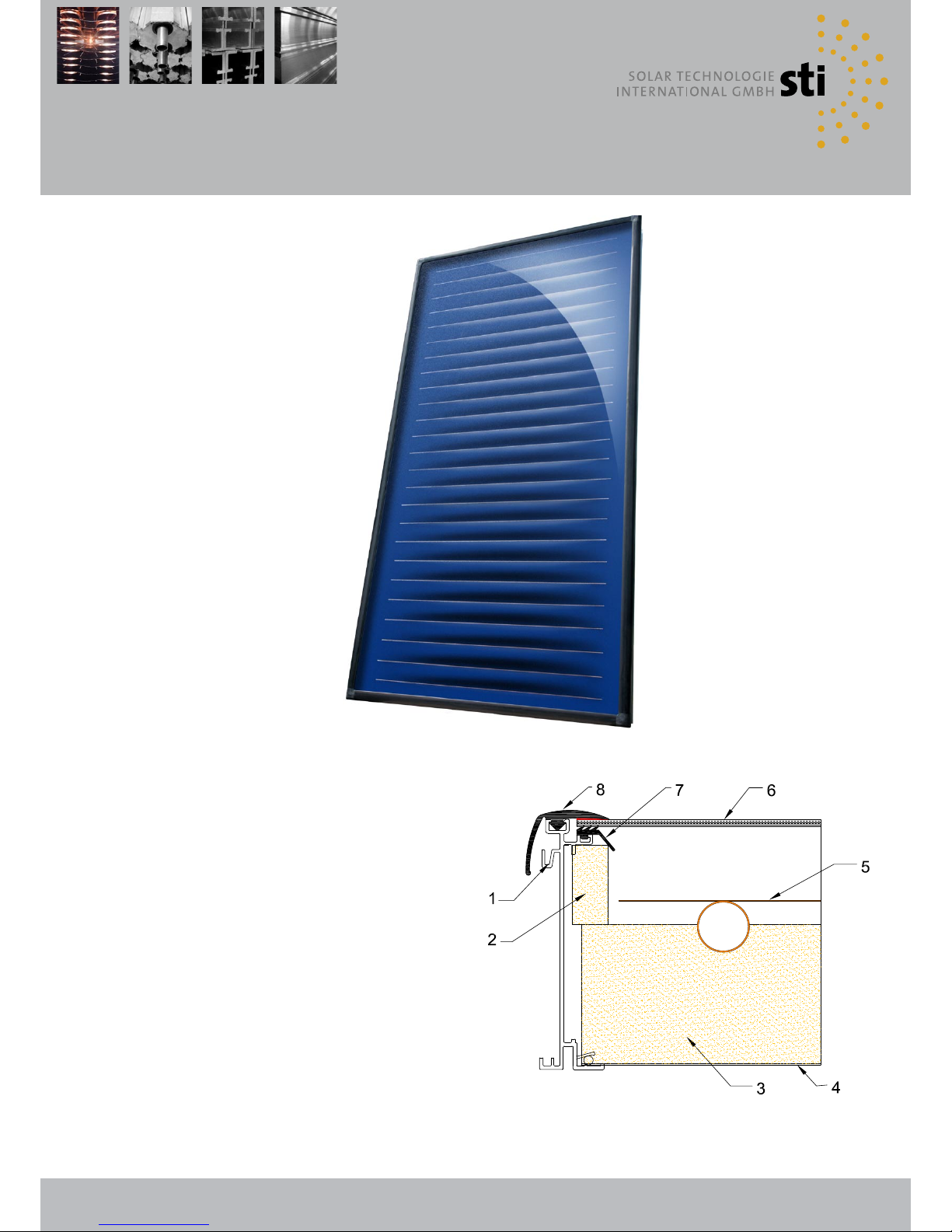
Product description
Solar collector FKA
The solar thermal collector FKA uses the radiant
energy of the sun to heat the heat transfer medium.
This glycol-water mixture gives off the stored heat via
a heat exchanger to a storage. The obtained energy
can be used for water heating and heating support.
Sectional model
1 Aluminium frame
2 Insulation
3 Insulation
4 Stucco back panel
5 Highly selective mono-material copper absorber
6 Glass
7 EPDM sealing
8 EPDM sealing
Page 6
6
Product description
FKA 240 V FKA 270 V
FKA 200 H
FKA 270 H
FKA 200 V
FKA 240 H
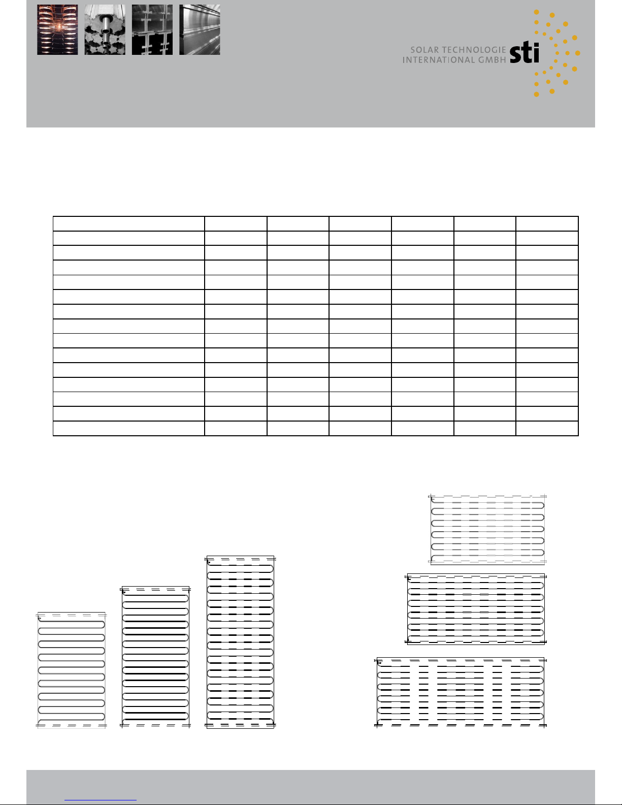
Specifications
The FKA collector has a pure copper absorber with meander shaped tubes as well as
integrated manifolds. The hydraulic system enables to connect 15 collectors in one series
and up to six collectors on one side. In one collector field up to 45 collectors can be
connected in three rows.
Hydraulic system of the absorber
Model FKA 200 V 240 V 270 V 200 H 240 H 270 H
Gross surface 2.13 m² 2.52 m
²
2.88 m² 2.13 m² 2.52 m² 2.88 m²
Net surface 1.80 m² 2.15 m
²
2.52 m² 1.80 m² 2.15 m² 2.52 m²
Length 1,777 mm 2,100 mm 2,400 mm 1,200 mm 1,200 mm 1,200 mm
Width 1,200 mm 1,200 mm 1,200 mm 1,777 mm 2,100 mm 2,400 mm
Height 115 mm 115 mm 115 mm 115 mm 115 mm 115 mm
Test pressure 10 bar 10 bar 10 bar 10 bar 10 bar 10 bar
Operating pressure 6 bar 6 bar 6 bar 6 bar 6 bar 6 bar
Fluid volume Co-Co / Al-Co 2.1 l 2.2 l 2.4 l 2.7 l 2.7 l 3.1 l
Fluid volume Al-Al 1.8 l 1.9 l 2.1 l 2.4 l 2.4 l 2.7 l
Flow per m
2
15 - 40 l/h 15 - 40 l/h 15 - 40 l/h 15 - 40 l/h 15 - 40 l/h 15 - 40 l/h
Weight Co-Co 38 kg 41 kg 44 kg 38 kg 41 kg 44 kg
Weight Al-Co 37 kg 40 kg 43 kg 37 kg 40 kg 43 kg
Weight Al-Al 36 kg 38 kg 41 kg 36 kg 38 kg 41 kg
Loss of pressure (T=20°C / 30l/h) 6,141 Pa 8,522 Pa 11,217 Pa 4,082 Pa 6,297 Pa 7,988 Pa
Page 7
7
Hydraulic connections
A B
C
E
G
D
F
H
Temperature sensor
Each collector has a sleeve for inserting a temperature sensor. The sleeve is directly connected with the absorber.
If the collectors are installed correctly, the sleeve is always located on the top of the collector on the left. The
temperature sensor can be inserted in any collector. Please pay attention to the maximum inserting depth of 4 cm
and secure it against slipping out. Due to the measuring point on the absorber the temperature measured by the
sensor may differ from the fluid temperature.
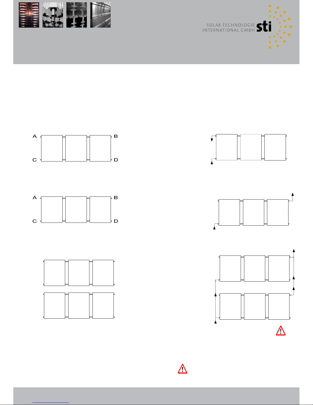
Installations with one up to six collectors in one row
Connection F red
Connection BF blue,
A or B
C or D
Close unused connections with
caps.
Installations with seven up to 15 collectors in one row
Connection bottom left / at the top of
the right
BF = C / F = B
Connection at the top of the left /
bottom right
BF = D / F = A
Multi-row installations
F=Flow (collector to storage) red grommet
BF=Backflow (storage to collector) blue grommet
In case of installation of an air eliminator, install it at the opposite
end of the top flow connection!
Pipe rounting by Tichelmann
Connection F A + E / BF H + D
Connection F B + F / BF G + C
Close unused connections with caps.
In case of multi-row installations the connection pipe must always be connected to the diagonal line to the external
manifold (Tichelmann), e.g. from botton left to the top right.
Page 8
8
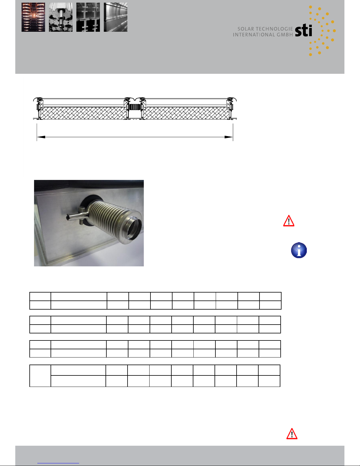
Collector field dimensions
Horizontal section across a collector field
Collectors that are mounted side by
side in one row are always connected
by means of stainless steel
expansion joints on the manifolds.
(view photo)
1300001 Collector connection set hydraulical
1910001 Tool set
Tighten the screw on the clamp only manually. The usage of
cordless screwdrivers or the like may lead to damages of the thread
of the clamp. Tighten the clamp until the two lugs are superimposed
in the whole length.
Field width
It is possible to assemble metal sheets between the collectors to achieve a homogeneous appearance of the installation.
The distance metal sheets are assembled exclusively for optical aspects and do not have any influence on the installation.
Therefore the distance metal sheets can be ordered optionally and are not necessarily included in delivery.
Collector type
When mounting solar collectors on supports it is important to ensure that the panels are anchored either on a solid surface or
on the concrete blocks shown in this instruction. The available concrete elements are recommended as a weight for locations
up to 700 meters above sea level with leeward situation. With expected higher loads, the weights must be increased. For higher
loads a calculation must be provided, and optionally a reinforcing of the system with additional components. When attaching
the consoles on buildings please ensure that the water tightness is maintained in each case. The mounting of the consoles and
collectors is described on the following pages.
240 H Number of collectors 1 2 3 4 5 6 7 8
Field width in mm 2.067 4.187 6.307 8.427 10.547 12.667 14.787 16.907
per each additional
collector
+ 2.120
270 H Anzahl Kollektoren 1 2 3 4 5 6 7 8
Field width in mm 2.340 4.733 7.126 9.519 11.912 14.305 16.698 19.091
per each additional
collector
+ 2.393
200 V
240 V
270 V
Number of collectors 1 2 3 4 5 6 7 8
Field width in mm 1.167 2.387 3.607 4.827 6.047 7.267 8.487 9.707
+ 1.220
per each additional
collector
200 H Number of collectors 1 2 3 4 5 6 7 8
Field width in mm 1.713 3.479 5.245 7.011 8.777 10.543 12.309 14.075
per each additional
collector
+ 1.766
Page 9
9
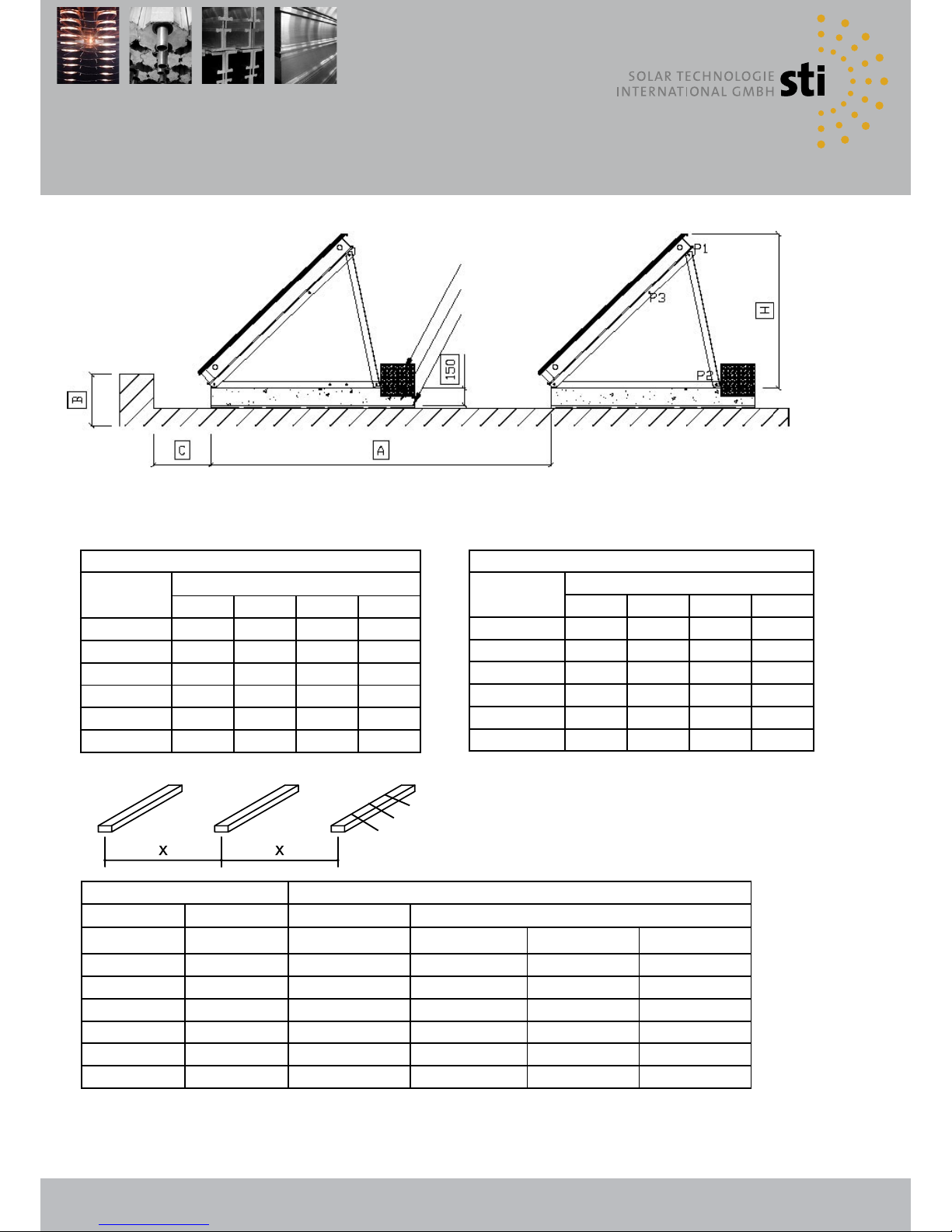
bottom support dimensions
α
δ
ε
bottom support
additional block
concrete block
base
row spacing of collectors
collector
type
distance A
20 ° 30 ° 45 ° 60 °
FKA 200 H 220 cm 265 cm 315 cm 340 cm
FKA 240 H 220 cm 265 cm 315 cm 340 cm
FKA 270 H 220 cm 265 cm 315 cm 340 cm
FKA 200 V 328 cm 391 cm 462 cm 503 cm
FKA 240 V 439 cm 513 cm 598 cm 646 cm
FKA 270 V 460 cm 550 cm 640 cm 700 cm
building height of collectors
collector
type
height H
20 ° 30 ° 45 ° 60 °
FKA 200 H 53 cm 71 cm 93 cm 110 cm
FKA 240 H 53 cm 71 cm 93 cm 110 cm
FKA 270 H 53 cm 71 cm 93 cm 110 cm
FKA 200 V 73 cm 91 cm 132 cm 156 cm
FKA 240 V 71 cm 104 cm 147 cm 180 cm
FKA 270 V 95 cm 130 cm 176 cm 211 cm
The specified levels are reported without concrete blocks. To
determine the total height the height of the concrete block
(15 cm) must be added.
Block distance center - center Dimensional chain, bottom bracket UK mounting
collector type
distance
Bottom support Bottom support attachment points (+ / - 30 cm)
X
α δ ε
FKA 200 H 176,6 cm 1000 mm 100 mm 860 mm -
FKA 240 H 212,0 cm 1000 mm 100 mm 860 mm -
FKA 270 H 239,3 cm 1000 mm 100 mm 860 mm -
FKA 200 V 122,0 cm 1600 mm 100 mm 700 mm 1.460 mm
FKA 240 V 122,0 cm 1600 mm 100 mm 700 mm 1.460 mm
FKA 270 V 122,0 cm 1800 mm 100 mm 900 mm 1.660 mm
All values given are recommendations for an effective angle of incidence of 20 °.
Please note the wind loads according to DIN 1055-4 in the edge region of the roof. The resulting base load is
necessary in each case to the requirement of wind loads on the spot!
Page 10
10
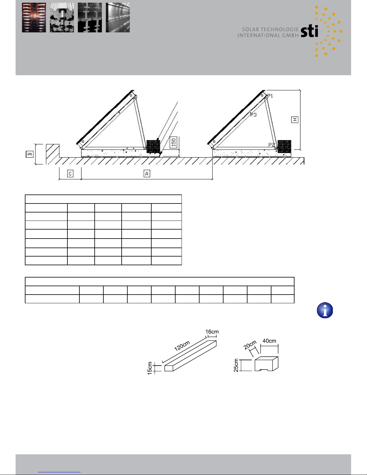
bottom support dimensions
distance of superstructures
parapet height B 30 cm 40 cm 50 cm 60 cm 70 cm 80 cm 90 cm 100 cm 110 cm
distance C 20 cm 40 cm 70 cm 100 cm 125 cm 150 cm 180 cm 205 cm 230 cm
1420100 concrete block 65 kg 1420101 additional block 45 kg
concrete block 65 kg
additional block 45 kg
console 8 kg
collector filled (240) 46 kg
travers position
angle 20° 30° 45° 60°
position P1 - P2 P3 - P2 P1 - P2 P3 - P2
200/240/270 H 487 mm 487 mm 861 mm 861 mm
200 V 675 mm 675 mm 1.224 mm 1.224 mm
240 V 832 mm 832 mm 1.490 mm 1.490 mm
position P1 - P2 P1 - P2 P1 - P2 P1 - P2
270 V 659 mm 962 mm 1.405 mm 1.820 mm
additional block
concrete block
base
Page 11

11
Assembly bottom support on
concrete block
First install the base console in accordance with the requirements to
the dimensions of bottom support.
1420014 bottom support 20°/30° 200 V
1420024 bottom support 45°/60° 200 V
1420018 bottom support 20°/30° 240 V
1420022 bottom support 45°/60° 240 V
1420060 bottom support 20° 270 V
1420061 bottom support 30° 270 V
1420062 bottom support 45° 270 V
1420063 bottom support 60° 270 V
1420011 bottom support 20°/30° 200/240/270 H
1420020 bottom support 45°/60° 200/240/270 H
Next place the concrete block. Pay attention to the exact
observance of the specified clearances between the concrete
blocks. The short distance between the threaded sleeve and block
edge (10 cm) shows the front of the block. Make sure that every
concrete block is on the same mounting position and aligned in a
row (e.g. by a line mark).
1420100 concrete block 65 kg
Now remove from all concrete blocks, the protective caps for the
integrated threaded sleeves.
Then place the base consoles on the concrete blocks and secure
them with the screws M10. All other consoles have to be oriented
exactly in a row (e.g. by a line mark).
1420003 Fastening set for bottom support
Now weight down the concrete block with the additional block.
Prepare for installing the collectors all consoles as above described.
1420101 additional block 45 kg
Page 12
12
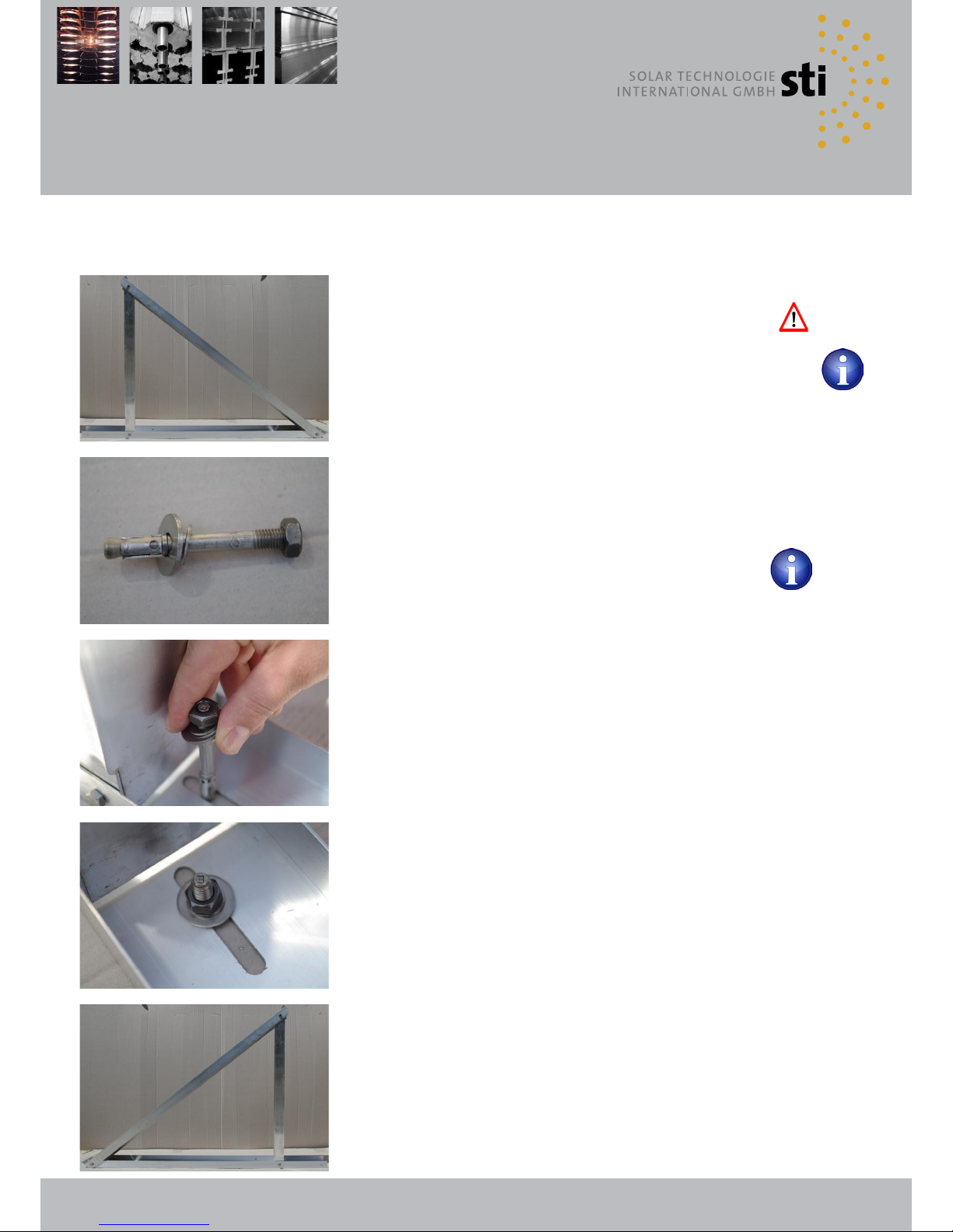
Assembly bottom support with
fixed dowel pin
First install the base console in accordance with the requirements
(see page 11).
1420014 bottom support 20°/30° 200 V
1420024 bottom support 45°/60° 200 V
1420018 bottom support 20°/30° 240 V
1420022 bottom support 45°/60° 240 V
1420060 bottom support 20° 270 V
1420061 bottom support 30° 270 V
1420062 bottom support 45° 270 V
1420063 bottom support 60° 270 V
1420011 bottom support 20°/30° 200/240/270 H
1420020 bottom support 45°/60° 200/240/270 H
Drill two holes per base console in the existing surface to fix the
fixed dowel pin M10. Pay attention to precise alignment of the two
holes. In addition, all other holes hare to be oriented in exactly one
row (e.g. by a line mark)
1420004 Fastening set for concrete blocks
(with fixed dowel pin)
Then place the base consoles on the ground and secure it with the
added fixed dowel pins M10. All other consoles have to be oriented
exactly in a row (e.g. by a line mark)
Fully assembled fixed dowel pin and console (see figure 1 and 2)
Fig. 1
Fig. 2
Reliable anchoring of the bottom support with the fixed dowelpin is possible in concrete <c25/25 as well as in natural stone that
is resistant to pressure.
Page 13

13
Assembly collectors
For the collector assembly, you first set the rightmost or leftmost
collector on the mounted and fixed consoles. When mounting the
collector ensure that the outer console is covered about 50% by the
collector.
After the exact orientation the collector is fixed on the outside with
fastening plates at the upper and lower elongated hole on the
console.
1400008 Collector fastening set onto support
edge (2 fastening points)
Please note that the remaining fastening plates are to mount on the
opposite outer side.
Before the following collectors can be mounted, the compensator
must be mounted on the concisely protruding flange.
It is important to ensure that the 0-ring seal is used for the
compensator.
1300001 Collector connection set hydraulical
Fixation of the compensator on one side with the clamp.
Before tightening the screw the clamp must be positioned by a
rotary motion up and down Tighten the screw on the clamp only
manually. The use of cordless drills or similar may cause damage
to the thread of the clamp. Tighten the clamp until the two lugs
superimpose in the whole length.
1910001 Tool set
Afterwards, mount the fastening plate “double” on the next console
in the upper and lower elongated hole. The final fixation takes place
after assembly of the next collector.
1400006 Collector fastening set onto support
(2 fastening points)
Page 14

14
Assembly collectors
Pre-installed compensator with O-ring seal and clamp. Install the
upper and lower compensator according to the opposite figure.
Now install the next collector on the consoles.
Move the collector until the fastening plate “double” hooks into the
collector profile. Then fix the fastening plate.
Fix the upper and lower compensator with the clamp.
Before tightening of the screw the clamp must be positioned by
a rotary motion up and down. Tighten the screw on the clamp only
manually. The use of cordless drills or similar may cause damage
on the thread of the clamp. Tighten the clamp until the two lugs
superimpose in the whole length.
Finally, assemble the two outer fastening plates.
Page 15

15
Temperature sensor
Each collector has a sleeve for inserting a temperature sensor.
The sensor is positioned below the upper left manifold or next to
the label with the description „top“ on the outside of the collector
frame.
The sleeve for inserting the sensor is protected with a silicon
grommet which has to be centrally opened (using a knife or small
screwdriver) before inserting the sensor.
The insertion depth is limited to 4 cm. Furthermore, it is
recommended to protect the sensor against slipping out.
The temperature sensor can be inserted in any collector of
the installation.
The error of measurement of the recorded temperature
compared to the fluid temperature is ± 2 K.
Page 16

16
Spacing roof hooks
A - 20 cm A +/- 20 cm
2 x A - 20 cm
2
Distance measures roof-tiles
Roof-tiles
roof covering
For each collector row two rows roof-tiles are necessary. The vertical size H1 is each taken on the top edge of
the roof-tiles.
Initial position:
top edge
roof-tiles
Initial position
1410002 Roof-tile bracket V2
..
..
..
1410005 Roof-tile bracket flat roof-tile
with lead 24 mm battens
If high snow loads are to be expected, the rooftiles have to be mounted above the rafters (in
other words the support must lie on the rafter /
alternatively, a higher number of roof-tiles may be
considered, depending on load).
Initial position:
top edge
roof-tiles
FKA 200/240/270 H
FKA 200/240/270 V
Horizontal size FKA 200 H FKA 240 H FKA 270 H
Maß A 88,3 cm 106 cm 119,7 cm
Vertical size
Tolerance
FKA 200 H
+ / - 10 cm
FKA 240 H
+ / - 10 cm
FKA 270 H
+ / - 10 cm
Maß H 77 cm 77 cm 77 cm
Horizontal size FKA 200 V FKA 240 V FKA 270 V
Maß A 122 cm 122 cm 122 cm
Vertical size
Tolerance
FKA 200 V
+ / - 10 cm
FKA 240 V
+ / - 10 cm
FKA 270 V
+ / - 10 cm
Maß H 1 60 cm 60 cm 80 cm
Maß H 2 77 cm 77 cm 77 cm
Page 17

17
Assembly base console
on roof profile
1400035 Profile set alu 200H
1400027 Profile set alu 240H
1400028 Profile set alu 270H
1400026 Profile set alu 200/240/270V
1400022 Connection set for
profile set
For roof-mounted installations one profile set alu 1400035, 1400026, 1400027 or 1400028 (depending on the collector type)
is delivered for each collector. If several collectors are mounted in one row, for each collector crossing one connection set for
profile set 1400022 is necessary.
For multi-row systems, the minimum distances between rows must be observed (see table “row spacing of collectors,“
bottom support dimensions).
Page 18

18
Assembly roof-tile clamps
Completely tiled roof.
When mounting the field in regions with high snow load zone of 2
kN/m², it is necessary to place the roof hooks in the rafter area.
Removal of the tiles after previous determination of the placement
of the roof-tile clamps (see page 10 “Spacing multi-row collector
fields“).
Fixation of the lower lath 24x80x600 mm with two screws 5x60 mm.
If the lath is placed near the counter lath, the lath 24x80x600 mm
must not be applied.
1410002 Roof-tile clamp V2 without lead
The lower roof-tile must be remounted.
Before covering the lower roof-tile must be coarsly ground.
To avoid breaking of the tile the roof-tile clamp must not rest on the
tile.
The lower tile must be coarsly ground so that the roof-tile clamp
rests in the middle of the tile.
Mount the tile clamp support 80x270x30 mm and fix it with two
screws 5x60 mm.
Page 19

19
Assembly roof-tile clamps
Fix the roof-tile clamp with the support 50x150x5 mm using two
screws 5x60 mm.
Before roofing the covering tile has to be coarsly ground accordingly.
Finished mounting of screw as distance saver.
Caulk, if necessary, the coarsely ground brick with a foam tape
against water!
In addition to the grinding of the roof-tile we recommend to use a
screw that is mounted on the roof-tile clamp support as distance
saver.
Complete covered roof-tile clamp after covering.
Further roof-tile clamps in one row must be adjusted exactly
(e.g. by a line mark)
Page 20

20
Assembly roof-tile clamps
with lead
Completely tiled roof.
Removal of the tiles after previous determination of the placement
of the roof-tile clamps (see page 10 „Spacing multi-row collector
fields“)
When mounting the field in regions with high snow load zone of 2
kN/m², it is necessary to place the roof hooks in the rafter area.
Completely lifted area for placement of a hook.
Mount the lower lath 24x80x600 mm with two screws 4x50 mm.
If the lath is placed near the counter lath, the lath 24x80x600 mm
must not be applied.
1410002 Roof-tile clamp V2 with lead
Replace the lower roof-tile.
Afterwards the tile clamp support 24x150x270 mm is to be fixed with
two screws 6x60 mm.
Page 21

21
Assembly roof-tile clamps
with lead
Place the first mounting tab so that the lower tile is covered.
Additionally make sure that the mounting tab is put sideways under
the adjacent tiles (bend up mounting tabs sidewise).
Mount the roof-tile clamps without covering the lower tile.
The roof-tile clamp must not cover the lower tile. Otherwise, a
pressure point on the lower tile may arise.
Mount the upper mounting tab. Bend it up sidewise. The screws of
the roof-tile clamp must be covered.
Protect the mounting tab against slipping.
The added foam wedge is placed under the adjacent tiles on both
sides as well as above (protection against splash water and snow).
Completely mounted roof-tile clamp.
Further roof-tile clamps in one row must be adjusted exactly
(e.g. by a line mark)
Page 22

22
Assembly plain tile clamps
without lead
Use the roof-tile for roof-mounted installation for plain tile roof covering also for slate, shingle and prefa covering.
Fixation of the lower lath 24x80x600 mm with two screws 4x50 mm.
If the lath is placed near the counter lath, the lath 24x80x600 mm
must not be applied.
Adjust the roof-tile laterally so that only one tile must be coarsly
ground. Place the hook so that there is enough space for a covering
tile to avoid grinding.
The tile clamp is fixed with two screws 5x60 mm.
The roof-tile clamp may not rest or rather cause pressure points on
the tile.
If the tile clamp is mounted too low, the added 5 mm timbers can be
placed under the tile clamp.
When mounting the field in regions with high snow load zone of 2
kN/m², it is necessary to place the roof hooks in the rafter area.
Covering of tile laterally.
Grinding and covering of the tile.
Covering of the remaining tiles.
Further roof-tile clamps in one row must be adjusted exactly
(e.g. by a line mark)
1410004 Roof-tile clamp V2 plain tile without lead
Page 23

23
Assembly plain tile clamps
with lead
Fixation of the lower lath 24x80x600 mm with two screws 4x50 mm.
Assembly of the upper tile clamp support 100x80x25 mm with two
screws 5x60 mm.
When mounting the field in regions with high snow load zone of 2
kN/m², it is necessary to place the roof hooks in the rafter area.
Assembly of the lower tile clamp supporte 80x50x45 mm with two
screws 5x60 mm.
Timber excess length of 5 mm (timber is higher than tile).
Completely mounted timber supports.
Mount the lower lead sheet while placing the lead laterally under the
tiles.
Pay attention that the corners are bent under the tile on both sides.
1410002 Roof-tile clamp V2 plain tile with lead
Page 24

24
Assembly plain tile clamps
with lead
Fixation of the roof-tile clamp with two screws 5x60 mm.
Screw the lower one into the tile lath and the upper one into the tile
clamp support.
Completely mounted roof-tile clamp with lower lead sheet.
The tile clamp must have a minimum distance to the underlying tile
of 5 mm.
Mount the upper lead sheet while placing the lead laterally under the
tiles.
Pay attention that the corners are bent under the tile on both sides.
See assembly lower lead sheet.
Covering of the upper tiles.
Completely mounted roof-tile clamp.
Further roof-tile clamps in one row must be adjusted exactly
(e.g. by a line mark)
Page 25

25
Assembly roof-tile clamp
corrugated
Pay attention that the clamps are placed near an existing mounting
lath.
The holes for the fixation screws have to be pre-drilled with a 8 mm
borer.
The fixation of the clamps is realised by façade screws 6,5x100 mm
with sealing gasket.
Depending on the width of the substructure underneath the
corrugated roof covering the roof clamp can additionally be fixed
with a second fastening screw.
Completely mounted roof clamp ready for assembly of fastening
profiles.
If the roof clamps can not be mounted within the limits indicated (see “Spacing roof hooks”), you first have to mount
horizontal or vertical STI system profiles onto the roof clamp. Afterwards the added fastening profiles are mounted.
1410001 Roof-tile clamp corrugated V2
The roof-tile clamps corrugated are suitable for roofs with a wooden substructure.
Page 26

26
Assembly mounting profiles/
console
Dachhaken
Readily mounted tile clamps for one collector field with two collectors.
Top: Tiles left out and clamp set with mounting tabs assembled
Bottom: Tiles coarsly ground and clamps assembled without
mounting tabs
Place the square bolts laterally into the profile into any groove.
1400026 Profile set Alu 200V, 240V and 270V or
1400035 Profile set Alu 200H or
1400027 Profile set Alu 240H or
1400028 Profile set Alu 270H
1400024 Fastening set for profile set on roof hooks (4 fast. pts.)
for every additional collector in one row
1400023 Fastening set for profile set on roof hooks (2 fast. pts.)
Fix the square bolts with the washer and the nut after putting it
through the slot.
Do not exceed the T-head screw‘s tightening torque of 27 Nm.
The slots in the hooks are for evening out bumps. The fastening of
the profile must be realised in the upper third of the slot.
In the border area of the fastening profile to be mounted the
connection profile has to be put in and centered; also at an angle of
90° to the square bolts.
Before joining the fastening profiles and connecting them with the
connection profile, the correct position is to be checked (level, line
mark). Subsequently, fix all setscrews M8x12 mm (connection set
and stop set).
1910001 Tool set
1400022 Connection set for profile set
After the roof hooks and mounting profiles are fixed, then you screw
the preassembled floor console with mounting profile. Remember to
mount the other consoles, the mounting dimensions on page 9.
The mounting of the collectors is described on the consoles on
page 12 and 13.
1400045 Fastening set console on profile
Page 27

27
Wall console dimensions
wall console
starting point:
center console
distance A (center-center)
distance = 2 x A
collector type FKA 200 H FKA 240 H FKA 270 H
measure A
1,766 mm 2,120 mm 2,393 mm
angle
H - measure
total high
Z -measure
hole spacing
W -measure
Upper edge of collector
mounting hole to top
T -measure
total depth
angle 20° 30° 45°
measure B 808 mm 1.106 mm 1.492 mm
measure H 1.140 mm 1.070 mm 910 mm
measure T 540 mm 710 mm 930 mm
measure W (Top of the collector. to hole center)
upper hole 96 mm 117 mm 140 mm
middle hole 176 mm 197 mm 220 mm
bottom hole 256 mm 277 mm 300 mm
measure Z (Hole spacing of the wall-side fixing holes)
Z 1 834 mm 753 mm 578 mm
Z 2 914 mm 833 mm 658 mm
Z 3 994 mm 913 mm 738 mm
B -measure
Minimum distance from
multi-row mounting
When mounting the fastening plates „edge“ the above
indicated dimensions should be used. After election, the
attachment of the outer panels made using mounting
plate „edge“, while the two outer brackets indented by 60
mm inside!
Page 28

28
Assembly wall console
90°
Wall console for mounting of collectors on façades, balcony railings
or other vertical building sections.
Install the wall console in accordance with the requirements of page
26.
1430001 Wall console 200/240/270 H 20° without fastening
1430002 Wall console 200/240/270 H 30° without fastening
1430003 Wall console 200/240/270 H 45° without fastening
Then place the wall console in the desired position. Make sure, that
all consoles have the same mounting position, the corresponding
distance measures between the consoles and the exact orientation
in a range (e.g. by a line mark).
The fastening of the console on the wall takes place on site, an
examination of the mounting surface and the choice of appropriate
fasteners is required.
see figure 3 and 4
Fig. 3
Fig. 4
Then place the first collector on the pre-assembled consoles.
Page 29

29
Assembly wall console
After the exact orientation the collector is fixed on the outside with
fastening plates at the upper and lower elongated hole on the
console.
1400008 Collector fastening set onto support
edge (2 fastening points)
Please note that the remaining fastening plates are to mount on the
opposite outer side.
Before the following collectors can be mounted, the compensator
must be mounted on the concisely protruding flange.
It is important to ensure that the 0-ring seal is used for the
compensator.
1300001 Collector connection set hydraulical
Fixation of the compensator on one side with the clamp.
Before tightening of the screw the clamp must be positioned by a
rotary motion up and down. Tighten the screw on the clamp only
manually. The use of cordless drills or similar may cause damages
on the thread of the clamp. Tighten the clamp until the two lugs
superimpose in the whole length.
1910001 Tool set
Afterwards, mount the fastening plate “double” on the next console
in the upper and lower elongated hole. The final fixation takes place
after assembly of the next collector.
1400006 Collector fastening set onto support
(2 fastening points)
Pre-installed compensator with 0-ring seal and clamp. Install the
upper and lower compensator according to the opposite figure.
Page 30

30
Assembly wall console
If the console is mounted flush with the outer collectors, these will
be fixed with the enclosed mounting plates. Install the set located at
the upper end of the console in the holes.
1400006 Collector fastening set onto consoles
1400008 Collector fastening set onto console edge
Now install the next collector on the consoles.
Move the collector until the fastening plate “double” hooks into the
collector profile. Then fix the fastening plate.
Fix the upper and lower compensator with the clamp.
Before tightening of the screw the clamp must be positioned by
a rotary motion up and down Tighten the screw on the clamp only
oganually. The use of cordless drills or similar may cause damages
on the thread of the clamp. Tighten the clamp until the two lugs
superimpose in the whole length.
Finally, assemble the two outer fastening plates.
Page 31

31
Temperature sensor
Each collector has a sleeve for inserting a temperature sensor.
The sensor is positioned below the upper left manifold or next to
the label with the description „top“ on the outside of the collector
frame.
The sleeve for inserting the sensor is protected with a silicon
grommet which has to be centrally opened (using a knife or small
screwdriver) before inserting the sensor.
The insertion depth is limited to 4 cm. Furthermore, it is
recommended to protect the sensor against slipping out.
The temperature sensor can be inserted in any collector of
the installation.
The error of measurement of the recorded temperature
compared to the fluid temperature is ± 2 K.
Page 32

32
Arrangement
hydraulic connections
Cap
is mounted on all non-used collector connections.
1310009 Cap set (1 pcs. compl.)
1310109 Cap set (1 pcs. compl.) Al
Connection 3/4“
1310005 Collector connection set R3/4“
(2 pcs. compl.)
Connection for reductions
1310004 Collector connection set 22 mm
(2 pcs. compl.)
1310104 Collector connection set 22 mm Al
(2 pcs. compl.)
Air eliminator without extension
1310007 Air eliminator set without extension pipe
(compl. with caps)
Completely mounted air eliminator
All other connections as well as the covers are mounted in the same
way.
The required connection dimension must be calculated by the
designer of the installation, depending on local conditions (line
lengths, additional resistors etc.).
Page 33

33
Overview hydraulic connections /
accessories
Hydraulic connections
Exhauster connection
For the installation at the
collector without extension
Collector connection 3/4“
for thread fittings
Collector connection 22 mm
for soldered fittings or clamping
ring joints
Collector connection hydraulical
(compensator)
connects two collectors and
compensates thermal dilations.
Clamp collector connection
and O-ring seal
Clamp for connection of the above
mentioned hydraulic devices with the
flange at the collector
Tool set Spare set hydraulical Assembling spare set
Accessories
Page 34

34
Assembly distance metal sheets
V V V
H H H
1 2
43
5 6
It is possible to mount metal sheets between the collectors for a homogenous appearance. The distance metal
sheets are only assembled for optical aspects and do not have any functional influence on the system. Therefore,
the distance metal sheets have to be ordered seperately and are not necessarily included in the delivery.
For the collector types FKA 200 V, FKA 240 V and FKA 270 V in every gap between the collectors two distance metal
sheets are mounted. For the collectors FKA 200 H, FKA 240 H and 270 H the assembly of one distance metal sheet is
planned. In case of multi-row systems, the distance metal sheets are mounted as described. The distance metal sheets
can be mounted from above or below.
Distance metal sheet
Distance metal sheets for the
assembly in one row
Fig. 1
The distance metal sheet is inserted from below into the collector
grooves.
Fig. 2 and 3
In case of vertical collectors or rather in case of multi-row assembly
of the collectors further distance metal sheets are inserted
subsequently from below. The lower distance metal sheet must be
pushed over the upper one to the notches.
Afterwards, the distance metal sheets are pushed upwards.
Fig. 4
The distance metal sheet is pushed upwards until it is flush with the
lip (collector covering).
top bottom
Fig. 5 and 6
To avoid injury, it is recommended to use a piece of wood to push
the distance metal sheets into the collector grooves. The distance
metal sheet is sticked in the collector groove to protect it against
slipping out. The silicone strip should have a length of 10 - 20 cm.
Please note that the distance metal sheet must be free of silicone
residue to ensure the flow of rain water.
1200043 Distance metal sheet FKA 200 V
1200039 Distance metal sheet FKA 240 V
1200040 Distance metal sheet FKA 270 V
1200042 Distance metal sheet FKA 240 H / 270 H
Page 35

35
Pipe dimensions
of the connecting pipe
Recommended pipe dimension of the connecting pipe
Length of pipe F + BF
Number of collectors
up to 10 m from 10 m
to 15 m
from 15 m
to 20 m
2 coll. - 132 L/h 12 x1 15 x 1 15 x 1
3 coll. - 198 L/h 15 x 1 15 x 1 15 x 1
4 coll. - 264 L/h 15 x 1 18 x 1 18 x 1
5 coll. - 330 L/h 18 x 1 18 x 1 18 x 1
6 coll. - 396 L/h 18 x 1 18 x 1 22 x 1
7 coll. - 462 L/h 22 x 1 22 x 1 22 x 1
8 coll. - 528 L/h 22 x 1 22 x 1 22 x 1
9 coll. - 594 L/h 22 x 1 22 x 1 22 x 1
10 coll. - 660 L/h 22 x 1 22 x 1 22 x 1
11 coll. - 726 L/h 22 x 1 22 x 1 28 x 1,5
12 coll. - 792 L/h 22 x 1 22 x 1 28 x 1,5
13 coll. - 858 L/h 22 x 1 28 x 1,5 28 x 1,5
14 coll. - 924 L/h 22 x 1 28 x 1,5 28 x 1,5
15 coll. - 990 L/h 22 x 1 28 x 1,5 28 x 1,5
Length of pipe F + BF
Number of collectors
from 20 m
to 25 m
from 25 m
to 30 m
from 30 m
to 35 m
from 35 m
to 40 m
2 coll. - 132 L/h 15 x 1 15 x 1 15 x 1 15 x 1
3 coll. - 198 L/h 18 x 1 18 x 1 18 x 1 18 x 1
4 coll. - 264 L/h 18 x 1 18 x 1 18 x 1 22 x 1
5 coll. - 330 L/h 22 x 1 22 x 1 22 x 1 22 x 1
6 coll. - 396 L/h 22 x 1 22 x 1 22 x 1 22 x 1
7 coll. - 462 L/h 22 x 1 22 x 1 22 x 1 28 x 1,5
8 coll. - 528 L/h 22 x 1 22 x 1 28 x 1,5 28 x 1,5
9 coll. - 594 L/h 22 x 1 28 x 1,5 28 x 1,5 28 x 1,5
10 coll. - 660 L/h 28 x 1,5 28 x 1,5 28 x 1,5 28 x 1,5
11 coll. - 726 L/h 28 x 1,5 28 x 1,5 28 x 1,5 28 x 1,5
12 coll. - 792 L/h 28 x 1,5 28 x 1,5 28 x 1,5 28 x 1,5
13 coll. - 858 L/h 28 x 1,5 28 x 1,5 28 x 1,5 28 x 1,5
14 coll. - 924 L/h 28 x 1,5 28 x 1,5 28 x 1,5 35 x 1,5
15 coll. - 990 L/h 28 x 1,5 28 x 1,5 35 x 1,5 35 x 1,5
Page 36

36
Pipe dimensions
of the connecting pipe
Recommended pipe dimensions of the connecting pipe
Length of pipe F + BF
Number of collectors
from 40 m
to 45 m
from 45 m
to 50 m
from 50 m
to 55 m
from 55 m
to 60 m
2 coll. - 132 L/h 18 x 1 18 x 1 18 x 1 18 x 1
3 coll. - 198 L/h 18 x 1 18 x 1 18 x 1 22 x 1
4 coll. - 264 L/h 22 x 1 22 x 1 22 x 1 22 x 1
5 coll. - 330 L/h 22 x 1 22 x 1 22 x 1 22 x 1
6 coll. - 396 L/h 22 x 1 22 x 1 22 x 1 22 x 1
7 coll. - 462 L/h 28 x 1,5 28 x 1,5 28 x 1,5 28 x 1,5
8 coll. - 528 L/h 28 x 1,5 28 x 1,5 28 x 1,5 28 x 1,5
9 coll. - 594 L/h 28 x 1,5 28 x 1,5 28 x 1,5 28 x 1,5
10 coll. - 660 L/h 28 x 1,5 28 x 1,5 28 x 1,5 28 x 1,5
11 coll. - 726 L/h 28 x 1,5 28 x 1,5 28 x 1,5 28 x 1,5
12 coll. - 792 L/h 28 x 1,5 35 x 1,5 35 x 1,5 35 x 1,5
13 coll. - 858 L/h 35 x 1,5 35 x 1,5 35 x 1,5 35 x 1,5
14 coll. - 924 L/h 35 x 1,5 35 x 1,5 35 x 1,5 35 x 1,5
15 coll. - 990 L/h 35 x 1,5 35 x 1,5 35 x 1,5 35 x 1,5
Page 37

37
Initial operation
Initial operation
After installing the other components such as flow
pipe, return pipe, insulation, pump group, expansion
tank and controller the installation can be put
into service. Perform a leak test and complete the
commissioning log.
Protect the collectors from direct sunlight if the filling
of the installation is not carried out within five days
after completion of the assembly.
Inspections within the first two weeks of
operation
• bleeding the solar circle.
• control system pressure
Instructions for the operation of the
installation
Carry out changes to the scheme and other system
components only after consultation and with inputs
from your specialized partner.
Ensure that an appropriate safety valve is mounted,
whose opening pressure is not exceeding the maximal operating pressure of the collectors.
Furthermore, do not install shut-off valves that may
affect or prevent the funtion of the safety valve.
Carry out maintenance and inspectionw with appropriate caution.
Certain components may reach temperatures up to
200° C. There is a risk of burns.
It is absolutely necessary to make sure that the
back flow temperature never falls below the ambient
temperature. If necessary, take appropriate measures
(e.g. increase of back flow temperature to at least
30° C.)
Regular inspections
Solar systems should be reviewed at intervals to be
determined in addition to the function control by the
operator.
The maintenance intervals of the system will be
defined during commissioning.
An annual review is recommended. The following components must be checked for proper function (if installed):
• solar collectors
• solar circle
• heat transfer fluid
• solar storage
• solar regulator incl. circulation pump
• supplementary heating system
Unscheduled maintenance
Depending on the location of the installation, environmental
influences may cause soiling on the collector glass (dust,
pollen etc.). Clean the glass, if necessary, exclusively with
clear water to ensure optimal light transmission.
If it is necessary to free the system from snow or ice, use
only non-metal cleaning equipment, such as brooms, with
due care.
Walk on roof areas only in compliance with all safety
aspects.
Heavy condensation may occur on the interior side of the
glass when defrosting while the collectors are covered with
snow. It is absolutely necessary to free the collectors from
snow to avoid damages due to humidity.
Page 38

38
Initial operation
Commissioning report
System operator Installer
Street Street
Postcode/City Postcode/City
Material Product Type
Special
feature
Material
Date of assembly
tick accordingly (description) (Serial N°) Net surface
Flat plate collector
Date of commissioning
Piping
Heat exchanger Type of installation
Storage 1 Content lit. Roof-integrated
Storage 2 Content lit. Roof-mounted
Solar regulation Console
Expansion tank Content lit. Safety valve bar
DrainMaster Content lit.
Collector adjustment south 0°, west +90°; east -90°) Setting angle of collectors
Height Meter
Setting value
(Control value=*)
Type /Programme
Maximum
temperature
Temperature
difference F / BF
Hysteresis
Consumer 1* = e.g. water for domestic use °C K K
Consumer 2* = e.g. 1. buffer store °C K K
Consumer 3* = e.g. 2. buffer store °C K K
Consumer 4* = e.g. swimming pool °C K K
Maximum temperatur of collector °C Solar protective function from °C Yes No
Operating pressure at bar System pressure expansion tank Debit: bar
Actual value:
bar
Heat transfer medium
Visual check normal/pink brown black murky
Type Minimum value Actual value
System
rinsed
Liquid capacity pH-value filtered
Ratio
Frost protection
bleeded
General system checkpoints
Collector clean ok Pumps tested on functionality ok
Stable collector fastening ok Temperature sensor shows realistic values ok
Collector not steamed up (interior) ok Grounding of the system ok
Non-return valve (not for DrainM.) ok Mixer - water for domestic use ok
Operating hours Pump 1 h Pump 2 h Calorimeter /kWh
Remarks:
Page 39

39
Appendix
Any guarantee and warranty for collectors as well as for resulting damages on the system or building expires due to
unauthorized changes on the collectors and the accessoiries
There is no guarantee or warranty due to optical or technical reduction or defects on the collector resulting from external
influences, forasmuch as these influences are not part of the supplier’s sphere of influence and they are not explicitly
known before execution.
Important to observe
Page 40

40
STI Solar Technologie International GmbH
Seiferitzer Allee 14
08393 Meerane
GERMANY
Tel: + 49 03764 795610
Fax: + 49 03764 7956115
E-Mail: info@sti-solar.de
Homepage: www.sti-solar.de
Copyright © STI Solar Technologie International GmbH 15.10.2012
 Loading...