

Page 1
Technical data
Installation
Assembly instruction DrainMaster
V-Series
Page 2
2
It is essential to read through this
instruction carefully prior to the
assembly and initial operation.
General safety instructions
Any installation activities have to be executed by
authorised professional staff. Please pay increased
attention to:
– the conditions on site
– the local regulations
– the recognized rules of engineering (especially
DIN 4757 Part 1 and 3)
– the proper state of the existing roof construction
– the safety rules concerning roof works
– the safety regulations for safety equipment
– the assembly instructions for components given
by your supplier
– the safety instructions of VDE and DVGW
Solely the constructor of the installation is resposible
for a proper assembly.
Functioning of the DrainMaster
The patented DrainMaster is an innovative solution
for draining solar systems. In doing so, only the
collector eld as well as the pipes above the
DrainMaster will be drained.
In a state of rest, the DrainMaster collects the heat
transfer medium. Thereby the installation is unable
to overheat and as a result, the heat transfer medium
and the system components will be protected. The
maintenance charges can be minised and running
the installation becomes safer.
The regulation of the DrainMaster is carried out by
the solar controller.
If there is a temperature measured at the collector
which differs by DeltaT from the temperature
measured in the tank, the circulating pump activates
automatically. The collectors will be lled with the
heat transfer medium which had been collected
in the DrainMaster and in the course of this, the
DrainMaster takes up the air pressed out. The
liquid which has been heated inside the collectors
circulates and heats the tank.
If DeltaT will be undershot or if a maximum
temperature will be reached in the collector, the
circulating pump deactivates, the collectors drain
and the liquid will be collected in the DrainMaster.
The covering of the DrainMaster is a particularly
manufactured aluminium prole for the assembly
with the collectors even outside of the roof cladding.
Any component which gets in contact with the heat
transfer medium is made of stainless steel. Please
make sure to not use material in the solar circuit
which might damage the stainless steel.
Construction of the DrainMaster
The collectors have to be self-draining. The piping
of the collectors has to enable an entire draining.
In the whole solar circuit (ow and backow), ap
valves must not be assembled. As the DrainMaster
enables a low system pressure, a safety valve of
3 bar is sufcient provided that the overall system
height permits it. Flow as well as backow should be
equipped with a syphon as closely as possible at the
heat exchanger so that a thermic pipe circulation can
be excluded.
System requirements
Operation Draining
Page 3
3
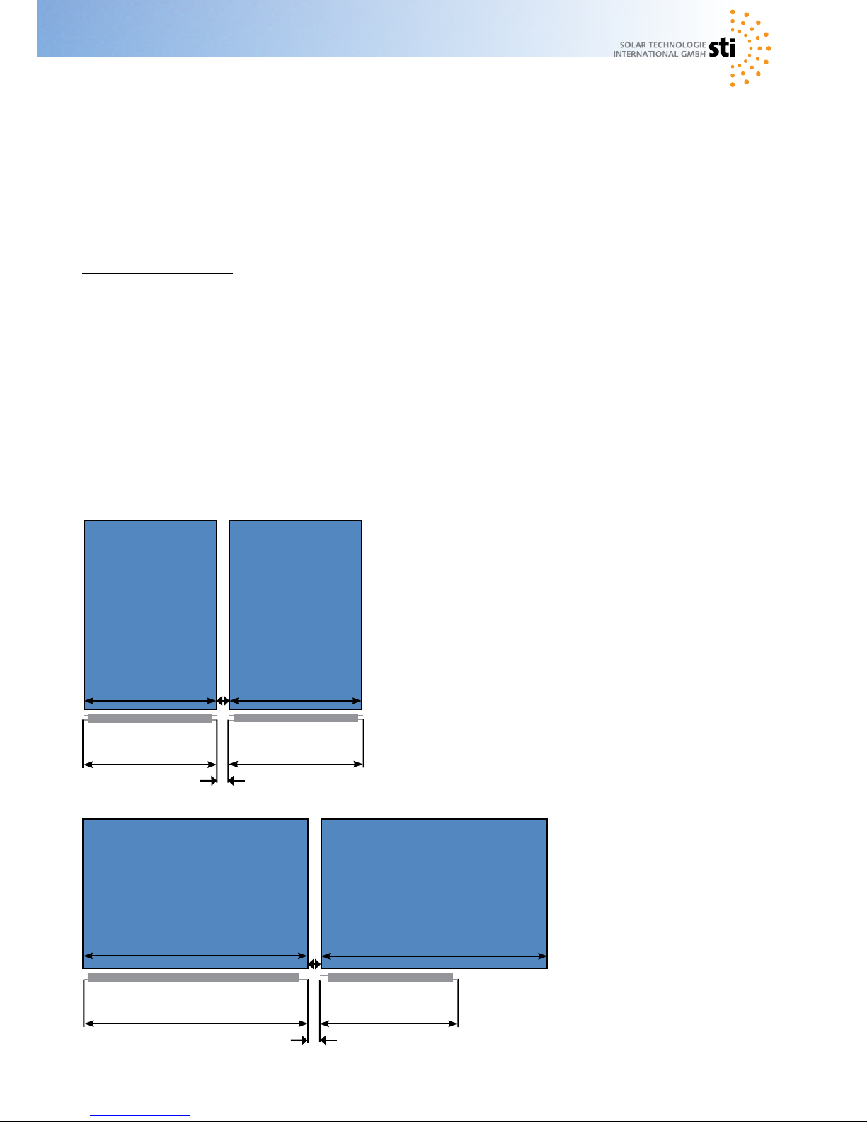
FKA 240
1190
1160
1190
1160
FKA
240
2090
2060
1190
2060
FKA 240FKA 240
FKA 240
60
60
30
30
FKA 240
Volume DrainMaster V-series
V 1190 (1190 mm) 7 l
V 2090 (2090 mm) 12,8 l
Example dimensioning:
Field of six collectors FKA 240V in two rows
Six collectors à 2,65 l
plus connection line ca. 1 l / m
= 16,9 l volume collector eld
Selection of DrainMasters:
Roof-mounted / 1 Basic module V 1190
bottom support: 3 Extension module V 1190
Roof-integrated 1 Basic module V 2090
3 Extension module V 1190
Dimensioning
The DrainMaster always has to be able to take
the whole quantity of liquid of the collector
eld including the connection line above the
DrainMaster.
If there are any insecurities, please contact your
specialist retailer.
Beside the basic module with a degassing and
perfusion zone, extension modules are available for
installations with a higher volume.
These extensions increase the usable volume range
if the installation is in stagnation.
Grid dimension
The DrainMaster series had been adjusted to the
collector FKA 240. Two different lengths can be
offered which refer to the collector types FKA 240 V
(2,2 l) abd FKA 240 H (2,65 l).
When assembling roof-integrated installations with
a sheet metal surrounding, the two DrainMaster
versions can be combined by a modular construction.
(Combination is possible
for roof-integrated installations.)
Page 4

4
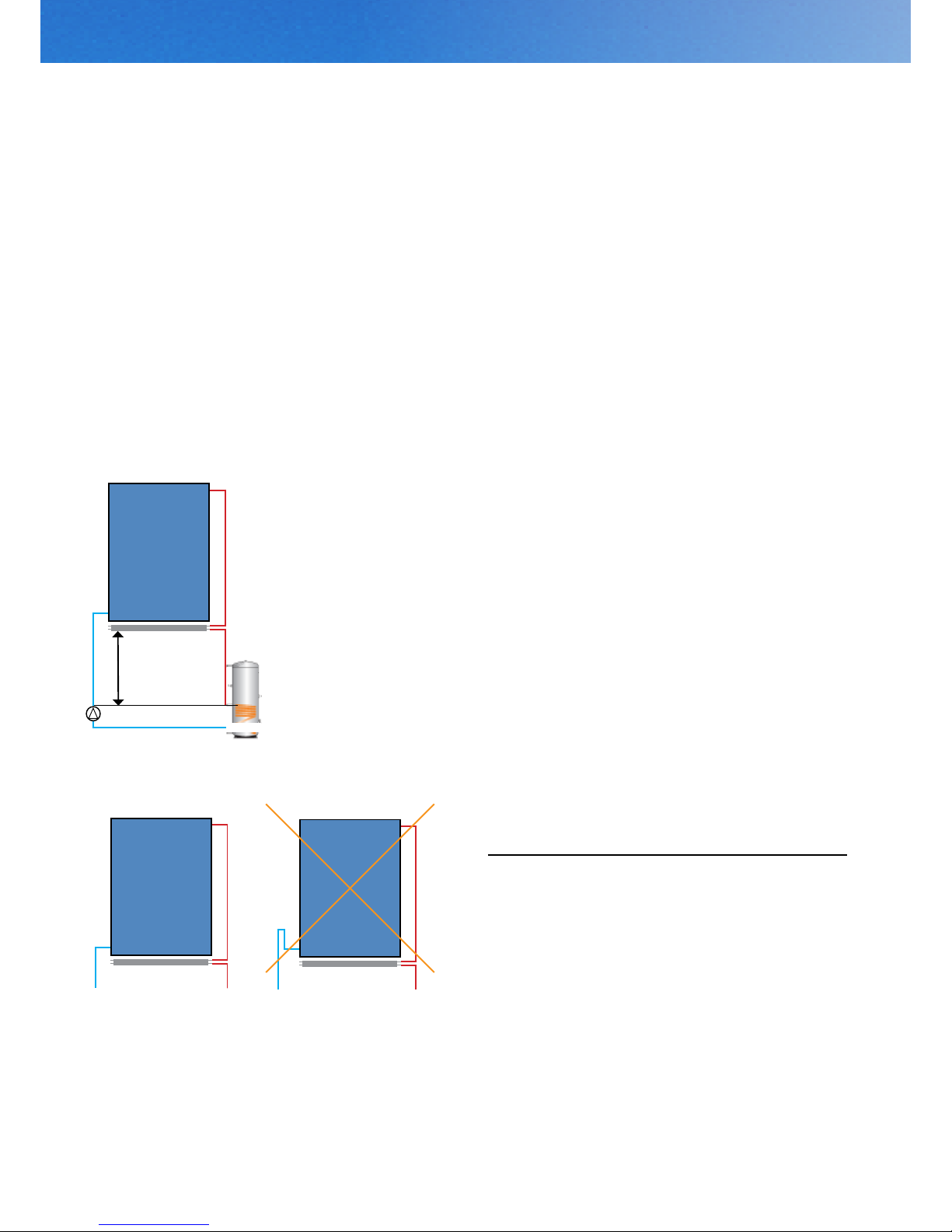
min. 50 cm
Roof-integrated installation
The DrainMaster is suitable for an assembly directly
below the collectors. In doing so, it is necessary to
observe that the DrainMaster always has to be assembled below the lowest edge of the collectors, but
at least 50 cm higher than the circulating pump and
the heat exchanger.
Alignment of the connections
The DrainMaster has to be adjusted in such a way
that the inow and outow can be arranged as vertical as possible (turn the DrainMaster so that the connections are perperndicular).
The connection which is marked with the red label is
the opening of the DrainMaster on top.
Connecting pipes
Please pay increased attention that the connecting
pipes from the collector eld to the DrainMaster do
not present any counter inclination (or syphon).
When installing the backow and the ow above the
lowest edge of the collector eld (e. g. above the
ridge sheet), please pay attention that the backow
(cold side) will be led to the level of the DrainMaster
by a syphon and that it will be piped with a pipe diameter up to the highest point in accordance with the
table below.
Number of collectors - wire cross section [mm]
1 12
2 12
3 18
4 20
5 22
6 22
Page 5

5
Roof-integrated installation
Assembly steps
1. Lie the DrainMaster onto the rafters below the lowest collector row.
2. Afterwards, please insert the mounting brackets
(2 per DrainMaster) into the cover of the DrainMaster
with a respective distance of 20 cm from the edge.
3. The DrainMaster has to be turned so that the area
with the elongated hole rests on the stop lath.
4. Adjust the DrainMaster succintly with the collector
ends and x it. In doing so, please pay attention that
the DrainMaster will be installed with an inclination
of 0,1 - 1 %. This means that the connections of ow
and backow are located approx. 1 cm lower than the
side on which the extensions will be assembled.
5. Connect the collector eld outlet with the DrainMaster inlet (upper screwing, red label).
6. Connect the DrainMaster outlet with the collector
ow. Thereto, use the provided cutting ring couplings
90 °. Please pay attention that the cutting ring cuts at
least 5 mm from the end of the pipe.
7. Close open connectors which lie opposite the connection side with the provided cutting ring sealing
plug (when using extension modules at the end of
the assembly line).
Assembly of the extension modules
The assembly of extension modules happens just as
the assembly of the basic modules.
The modules will be coupled with the provided com-
pression ttings. It is necessary to observe that no
counter inclination emerges.
Page 6

6
min. 50 cm
Roof-mounted installation
The DrainMaster is suitable for an assembly directly
below the collectors. In doing so, it is necessary to
observe that the DrainMaster always has to be assembled below the lowest edge of the collectors, but
at least 50 cm higher than the circulating pump and
the heat exchanger.
Alignment of the connections
The DrainMaster has to be adjusted in such a way
that the inow and outow can be arranged as vertical as possible (turn the DrainMaster so that the connections are perperndicular).
The connection which is marked with the red label is
the opening of the DrainMaster on top.
Connecting pipes
Please pay increased attention that the connecting
pipes from the collector eld to the DrainMaster do
not present any counter inclination (or syphon).
When installing the backow and the ow above the
lowest edge of the collector eld (e. g. above the
ridge sheet), please pay attention that the backow
(cold side) will be led to the level of the DrainMaster
by a syphon and that it will be piped with a pipe diameter up to the highest point in accordance with the
table below.
Number of collectors - wire cross section [mm]
1 12
2 12
3 18
4 20
5 22
6 22
Page 7

7
Roof-mounted installation
Assembly steps
1. The DrainMaster will be installed after the assembly of the aluminium prole at the bottom. It is recommendable to x the DrainMaster prior to the
assembly of the collectors.
2. For this purpose, the two provided brackets for
each DrainMaster will be inserted into the slots of the
cover of the DrainMaster at both ends. The connections have to be aligned vertically. Please pay attention that the DrainMaster has to come to rest with its
entry (marked with a red label) at top.
3. Afterwards you have to plug the brackets from below onto the priorly placed wafer-head screws which
are located on the proles and secure it using a nut.
The elongated holes now enable a variable relocating of the DrainMaster.
4. Align the DrainMaster succintly with the collector
ends and fasten it. In doing so, please pay attention
that the DrainMaster will be installed with an inclination of 0,1 - 1 %. This means that the connections
of ow and backow are located approx. 1 cm lower
than the side on which the extensions will be assembled.
5. Connect the collector eld outlet with the DrainMaster inlet (upper screwing, red label).
6. Connect the DrainMaster outlet with the collector
ow. Thereto, use the provided cutting ring couplings
90 °. Please pay attention that the cutting ring cuts at
least 5 mm from the end of the pipe.
7. Close open connectors which lie opposite the connection side with the provided cutting ring sealing
plug (when using extension modules at the end of
the assembly line).
Assembly of the extension modules
The assembly of extension modules happens just as
the assembly of the basic modules.
The modules will be coupled with the provided com-
pression ttings. It is necessary to observe that no
counter inclination emerges.
Page 8
8
min. 50 cm
Installation on bottom supports
The DrainMaster is suitable for an assembly directly
below the collectors. In doing so, it is necessary to
observe that the DrainMaster always has to be assembled below the lowest edge of the collectors, but
at least 50 cm higher than the circulating pump and
the heat exchanger.
Alignment of the connections
The DrainMaster has to be adjusted in such a way
that the inow and outow can be arranged as vertical as possible (turn the DrainMaster so that the connections are perperndicular).
The connection which is marked with the red label is
the opening of the DrainMaster on top.
Connecting pipes
Please pay increased attention that the connecting
pipes from the collector eld to the DrainMaster do
not present any counter inclination (or syphon).
When installing the backow and the ow above the
lowest edge of the collector eld (e. g. above the
ridge sheet), please pay attention that the backow
(cold side) will be led to the level of the DrainMaster
by a syphon and that it will be piped with a pipe diameter up to the highest point in accordance with the
table below.
Number of collectors - wire cross section [mm]
1 12
2 12
3 18
4 20
5 22
6 22
Page 9

9
Installation on bottom supports
Assembly steps
1. The DrainMaster has to be mounted after the assembly of the bottom supports but prior to xing the
collectors.
2. Thereto, two assembly brackets are needed for
each DrainMaster. In order to x the bottom supports, the lower screws which are at the front of the
consoles have to be loosen and afterwards be xed
with the brackets. The small elongated hole of the
brackets has to be the one which is up.
3. The upper elongated hole serves for an additional
xtation of the collectors with a onefold rail clip.
4. Afterwards, the brackets for the DrainMaster have
to be inserted into the provided rail at the cover of the
DrainMaster (2 pieces for each DrainMaster). They
then have to be moved so that they come to rest abo-
ve the assembly brackets and have to be xed with
a screw. When installing the rst DrainMaster, they
necessarily have to be xed at the very top in the
elongated holes and accordingly be adapted for the
following ones.
5. Align the DrainMaster succintly with the collector
ends and fasten it. In doing so, please pay attention
that the DrainMaster will be installed with an inclination of 0,1 - 1 %. This means that the connections
of ow and backow are located approx. 1 cm lower
than the side on which the extensions will be assembled.
6. Connect the collector eld outlet with the DrainMaster inlet (upper screwing, red label).
7. Connect the DrainMaster outlet with the collector
ow. Thereto, use the provided cutting ring couplings
90 °. Please pay attention that the cutting ring cuts at
least 5 mm from the end of the pipe.
8. Close open connectors which lie opposite the connection side with the provided cutting ring sealing
plug (when using extension modules at the end of
the assembly line).
Assembly of the extension modules
The assembly of extension modules happens just as
the assembly of the basic modules.
The modules will be coupled with the provided com-
pression ttings. It is necessary to observe that no
counter inclination emerges.
Page 10
10
Filling of the system
6. Now you have to drain the following quantity of liquid:
Quantity A: 0,17 l for each liter of liquid content in the
DrainMaster (for 10 l liquid content in the DrainMaster
= 1,7 l)
Quantity B: 0,04 times installation content (for 30 l
installtion content = 1,2 l)
Total draining quantity = quantity A + quantity B (example 1,7 l + 1,2 l = 2,9 l)
7. Close the shut-off valve at the pressure-side of
the pump again and ll in quantity A. By doing so
the necessary prepressure of the installation can be
reached.
8. Now the report of the controller should disappear
or the collector temperature should appear. If an error
report or the report „lling level reached“ is shown,
the installation is overlled and has to be drained until
the report diappears.
9. Open the shut-off valve, close the lling and draining valve and switch on the pump. Check the functionality of the installation and switch over to an automatic operation.
Installation without level indicator
1. Close the shut-off valve in the collector back ow
(pressure-side of the pump).
2. Loosen the upper connection at the DrainMaster.
3. Open the lling and draining valve, connect the
lling pump and slowly ll the installation until the
DrainMaster is completely lled with liquid.
4. Close lling and draining valve and open the shut-
off valve (pressure-side of the pump).
5. Slowly rell the liquid until the DrainMaster is completely completely lled.
6. Now you have to drain the following quantity of liquid:
Quantity A: 0,17 l for each liter of liquid content in the
DrainMaster (for 10 l liquid content in the DrainMaster
= 1,7 l)
Quantity B: 0,04 times installation content (for 30 l
installtion content = 1,2 l)
Total draining quantity = quantity A + quantity B (example 1,7 l + 1,2 l = 2,9 l)
Attention!
When lling the installation, the solar uid must not
be warmer than 25 °C!
The circulating pump must not be working while lling.
Filling under cloudy skies
The prepressure of the installation is calculated as
follows:
Prepressure in bar = static height in meter / 10 + 0,2
Filling in sunshine
The prepressure of the installation depends on the
temperature of the collector during the lling.
Rule of thumb for the prepressure:
Prepressure in bar = static height in meter / 10 + 0,2
+ gure stated below:
For collector temperature of approx. 50 °C + 0,1 bar
For collector temperature of approx. 100 °C + 0,2 bar
For collector temperature of approx. 150 °C + 0,3 bar
For collector temperature of approx. 200 °C + 0,4 bar
Installation with level indicator
1. Close the shut-off valve in the collector back ow
(pressure-side of the pump).
2. Open the lling and draining valve of the safety
device.
3. Connect the lling pump at the lling and
draining valve at the suction side of the pump. Fill
the installation slowly until the probe presents the
maximum lling level (when using special controllers,
the report „maximum lling level reached“ is going
to be shown).
4. Close lling and draining valve and open the
shut-off valve (pressure-side of the pump).
5. Slowly ll in the liquid until the probe presents
the maximum lling level once again (when using
special controllers, the report „maximum lling level
reached“ is going to be shown).
Page 11

11
7. Tighten the upper connection at the DrainMaster.
8. Close the shut-off valve at the pressure-side of the
pump again and ll in quantity A. By doing so the
necessary prepressure of the installation can be reached.
9. Open the shut-off valves, close the lling and
draining valve and switch on the pump. Check the
functionality of the installation and switch over to an
automatic operation.
Frost resistance
We recommend operating the installation with
an antifreeze mixture.
In case of damages due to frost, we do not
assume no liability.
General information
A solar plant should be maintained every year. In doing so, the functionality of all components should be
examined, especially the heat transfer medium has to be checked for its quantity and state. When installing
a DrainMaster into an already existing installation, it is necessary to pay attention that the heat transfer me-
dium (if it is still all right) can only be relled with the same type. We recommend to entirely exchange the old
medium.
Identied disorder Possible cause Problem solving
Wrong / no temperature indicator Probe defect Exchange of the probe by a
specialist
Wrong lling Repetition of the lling process
Pump is working / Air in the pump Repetition of the process,
no circulation of the medium venting of the pump
System pressure is too high Wrong dimensioning Reexamination of the volume
calculation
Installation does not drain Non-return valves are Removal or blocking of the non probably still existing return valves
Installation drains badly or Collectors are not piped properly Examination of the piping consivery slowly dering the draining aspect
DrainMaster is not assembled Check of the permitted assembly
properly arrangements
Fault diagnosis
Page 12

© Copyright 2016
Version 02/2016
STI Solar Technologie International GmbH
Seiferitzer Allee 14
08393 Meerane
GERMANY
Tel: + 49 03764 795610
Fax: + 49 03764 7956115
E-Mail: info@sti-solar.de
Homepage: www.sti-solar.de
 Loading...