

Page 1
CMCP7504
Machine Monitoring System
User Manual
Copyright 2018 by STI Vibration Monitoring Inc.
All Rights Reserved
Rev. 2.0
Page 2

STI Vibration Monitoring Inc.
CMCP7504
2
Table of Contents
System Overview .......................................................................................................................................... 4
Introduction to the CMCP7504 ................................................................................................................. 4
Additional System Features .......................................................................................................................... 5
Function and Parts Description ................................................................................................................. 6
Input Module Characteristics ........................................................................................................................ 6
Frequency Ranges ..................................................................................................................................... 6
Setting The Full Scale Range and Frequency Ranges ................................................................................ 7
(AA) Acceleration Module ..................................................................................................................... 7
(AV) Velocity Module – Accelerometer Input ....................................................................................... 8
(VV) Velocity Module Input – Velocity Sensor Input ............................................................................ 9
(RV) Radial Vibration Module– Proximity Probe Input ....................................................................... 10
(EV) Enveloped Acceleration Module– Accelerometer Input ............................................................. 11
(AM) Analog Input Module – Voltage or Current ............................................................................... 12
(TM) Analog Input Module – Voltage or Current ................................................................................ 13
General Wiring ............................................................................................................................................ 14
Buffered Outputs and Analog Outputs ................................................................................................... 14
Analog Inputs .......................................................................................................................................... 15
Alert and Danger Relay Outputs ............................................................................................................. 16
System OK Relay and System Power ....................................................................................................... 17
Configuration Software Overview (MMS Manager) ................................................................................... 18
Measurement Point Name ...................................................................................................................... 18
Input Signal Type ..................................................................................................................................... 18
Engineering Units .................................................................................................................................... 19
Alarm Level Setup and Relay State ......................................................................................................... 19
Relay Operating Type .............................................................................................................................. 19
Bypass ..................................................................................................................................................... 20
Relay NE/NDE .......................................................................................................................................... 20
Relay Delay Time (ms) ............................................................................................................................. 20
Signal Scaling ........................................................................................................................................... 20
View Scale ............................................................................................................................................... 21
4-20mA Offset ......................................................................................................................................... 21
Uploading Configuration Files (Set Data) .................................................................................................... 22
Saving the Configuration File (Save File) ..................................................................................................... 22
Page 3

STI Vibration Monitoring Inc.
CMCP7504
3
Uploading Configuration File (Load File) ..................................................................................................... 22
Configuring the Modbus RS485 Output ...................................................................................................... 22
Modbus Communications Setup ............................................................................................................. 22
Technical Specifications .............................................................................................................................. 23
Sample Wiring Diagrams ............................................................................................................................. 24
Page 4

STI Vibration Monitoring Inc.
CMCP7504
4
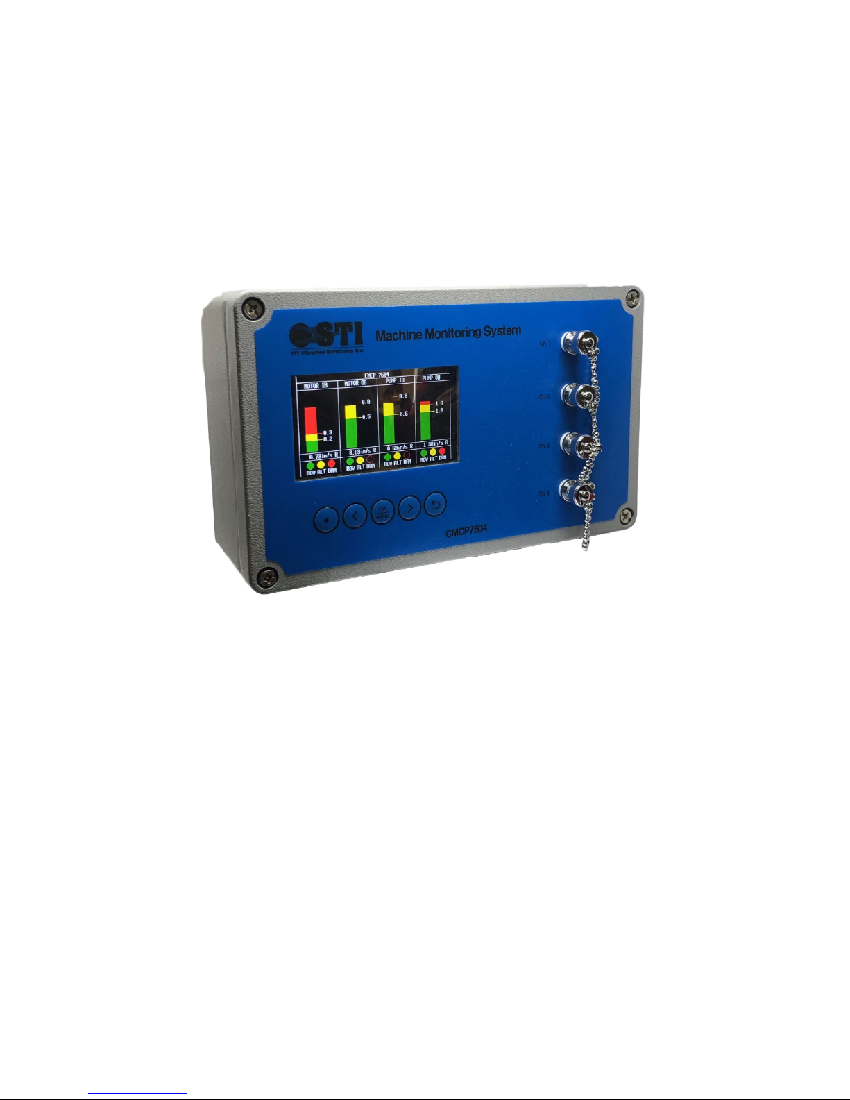
System Overview
STI’s CMCP7504 is a general-purpose monitoring system capable of continuously monitoring up to 4
channels of vibration, position or temperature. The CMCP7504 can be configured to operate as a
standalone protection system or it can be connected to a host device such as a PLC, DCS or SCADA
system. Local bar graph displays provide the overall amplitudes and alarm status along with a user
identifiable tag name.
Introduction to the CMCP7504
The STI CMCP7504 System is comprised of a series of sub-modules:
AA - Acceleration Module
VA - Velocity Module, Accelerometer Input
VV - Velocity Module, Velocity Sensor Input
EV - Enveloped Acceleration Module, Accelerometer Input
RV - Radial Vibration Module, Proximity Probe Input
TP - Thrust Position Module, Proximity Probe Input
AM - Analog Input Module, 4-20mA or 1-5 VDC Input
TM - Temperature Input, 100 Ohm Platinum RTD or 10mV/Deg. C
The (AA) Acceleration Module is for connecting to Piezoelectric accelerometer with a mV/g output.
The signal is processed for continuous monitoring and the overall amplitude is converted into a 420mA output, proportional to the full-scale range selected, for transfer to a PLC, DCS or other facility
control system. Acceleration can be displayed in g’s with either RMS or Peak detection.
The (VA) Velocity Module is for connecting to Piezoelectric accelerometer with a mV/g output. The
signal is processed for continuous monitoring and the overall amplitude is converted into a 4-20mA
output, proportional to the full-scale range selected, for transfer to a PLC, DCS or other facility
control system. Velocity can be displayed in terms of either in/Sec or mm/Sec with either RMS or
Peak detection.
The (VV) Velocity Module is for connecting to Piezo-Velocity sensor with a mV/in/s or mV/mm/s
output. The signal is processed for continuous monitoring and the overall amplitude is converted
into a 4-20mA output, proportional to the full-scale range selected, for transfer to a PLC, DCS or
other facility control system. Velocity can be displayed in terms of either in/Sec or mm/Sec with
either RMS or Peak detection.
The (EV) Enveloped Acceleration Module is for connecting to a Piezoelectric accelerometer with a
mV/g output. The signal is processed to calculate an Acceleration Enveloping value within a selected
bandwidth, 0-1,000Hz (Filter #2) or 500-10,000Hz (Filter #3) for continuous monitoring and the
overall amplitude is converted into a 4-20mA output, proportional to the full-scale range selected,
for transfer to a PLC, DCS or other facility control system. Enveloped Acceleration can be displayed in
terms of gE.
The (RV) Radial Vibration Module is for connecting to eddy current probe systems (also referred to as
a proximity probe system) with a mV/mil or mV/mm output. The signal is processed for continuous
monitoring and the overall amplitude is then converted into a 4-20mA output for transfer to a PLC,
DCS or other facility control system. Radial vibration can be displayed in terms of mils or microns
Peak to Peak. The CMCP7504 does not provide -24VDC power to the eddy probe system.
Page 5

STI Vibration Monitoring Inc.
CMCP7504
5
The (TP) Thrust Position (Axial Position) Module is for connecting to eddy current probe system (also
referred to as a proximity probe system) with a mV/mil or mV/mm output. The signal is processed
for continuous monitoring and the overall amplitude is then converted into a 4-20mA output for
transfer to a PLC, DCS or other facility control system. Thrust Position can be displayed in terms of
millimeters (mm) or microns (um). The CMCP7504 does not provide -24VDC power to the eddy
probe system.
The (AM) Analog Input Module is for connecting an analog signal (4-20mA or 1-5VDC). The signal is
processed for continuous monitoring and the overall amplitude is then converted to a 4-20mA
output for transfer to a PLC, DCS or other facility control system. Analog Inputs can be displayed in
the user choice of terms.
The (TM) Temperature Input Module is for connecting either a 100 Ohm Platinum RTD or, most
commonly, a 10mV/°C signal from a dual output accelerometer such as STI’s CMCP786T or
CMCP785T. The signal is processed for continuous monitoring and the overall amplitude is then
converted to a 4-20mA, proportional to the full-scale range selected, for transfer to a PLC, DCS or
other facility control system. Temperature inputs can be displayed in terms of °C or °F.
The (XX) Empty Input Module is for when an input module is left empty, allowing the user to order
the system as a 1, 2 or 3 channel monitoring system.
Additional System Features
Relays and Alarms
The CMCP7504 Machine Protection System is designed to comply with the API 670 standard and offers
machine protection functions. The CMCP7504 provides 2 relay contact outputs, 1 for alert and 1 for
danger, for each channel. A global System OK relay is also provided. Local alarm status for each channel is
also provided on the bar graph display.
Buffered Outputs
For each channel, the sensor’s raw signal is available as a buffered output. Buffered outputs for each
channel are available at the BNC connector, located on the front cover, and at the terminal strip on the
main board. These buffered outputs are commonly used to connect portable data collectors or
permanently installed analysis devices in parallel to the CMCP7504 for FFT diagnostics.
Analog Outputs
The CMCP7504 provides a 4-20mA output for each channel. The 4-20mA output is proportional to the
full-scale range selected on the input module.
Modbus Output
A two wire Modbus 485 (half duplex) output is available on the internal terminal strips. The CMCP7504
can be configured to act as a slave device to allow the overall values to be sent over Modbus 485.
Configuration Utility
The configuration of each channel’s processing parameters (for example the measurement units or alarm
setpoints) is performed using a simple configuration software called the MMS Manager. The MMS
Manager can be installed on a Windows operating system (2000 or newer) and connects to the
CMCP7504 using a generic USB cable which is supplied with the system.
Page 6
STI Vibration Monitoring Inc.
CMCP7504
6
Function and Parts Description
Module
Sensor Type
Frequency Range
(AA) Acceleration)
Accelerometer
2 to 20kHz
(AV) Velocity
Accelerometer
Default: 10 to 1,000 Hz (ISO)
Selectable: 2 to 2,000 Hz (ISO LF)
(VA) Velocity
Velocity Transducer
Default: 10 to 1,000 Hz (ISO)
Selectable: 2 to 2,000 Hz (ISO LF)
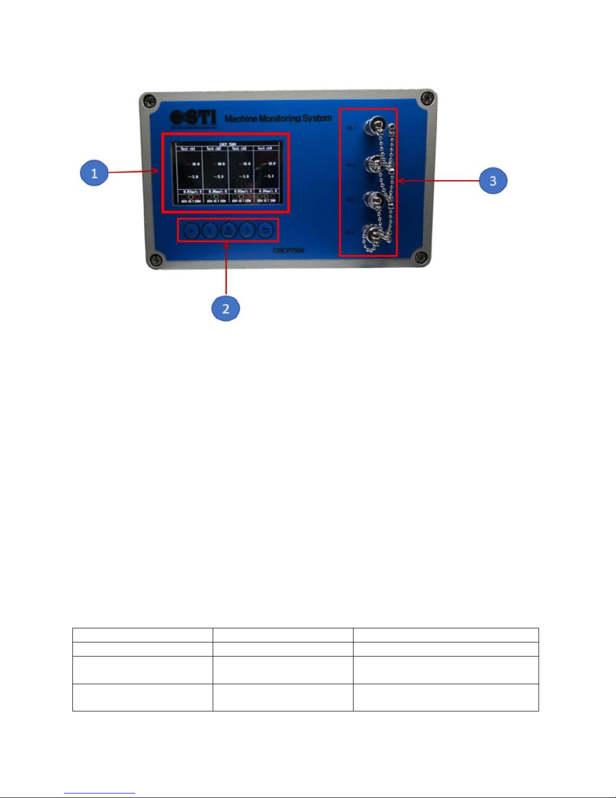
1. Display Module
The display module shows the overall value, bar graph, user defined alert and danger setpoints,
point name and sensor status for each channel.
2. Push Buttons
A push button keypad is used to reset the relays for each channel. To reset, simply highlight the
channel needed and click OK.
3. BNC Buffered Outputs
For each channel, the sensor’s raw signal is available as a buffered output at the front panel BNC
connector. The BNC connectors may be used to connect a portable data collector for further
signal diagnostics.
Input Module Characteristics
The CMCP7504 supports accelerometers, velocity transducers, eddy current probes (proximity probes)
and all voltage or current outputs sensors. Once processed, the data can then be used for continuous
monitoring and overall value transmission to a PLC, DCS or other control system. The table below shows
the standard processing parameters. When available, the frequency can be set using a jumper on each
input module. The frequency range is not selected using the MMS Manager.
Frequency Ranges
Page 7
STI Vibration Monitoring Inc.
CMCP7504
7
(EV) Enveloped Acceleration
Accelerometer
Selectable: 0 to 1,000 Hz (Filter #2)
Default: 500 to 10,000 Hz (Filter #3)
(RV) Radial Vibration
Eddy Current Probe
2 to 2,000 Hz
(TP) Thrust Position
Eddy Current Probe
DC
(AM) Analog Input
4-20mA or 1-5VDC
N/A
(TM) Temperature Input
100 Ohm RTD or 10mV/°C
N/A
Table 1: Available Sensor Inputs and Characteristics for the CMCP7504
Range 1
Range 2
Range 3
Range 4
Range 5
Input
(mV)
1,000
0.5
1.00
1.50
2.00
2.50
500
1.00
2.00
3.00
4.00
5.00
250
2.00
4.00
6.00
8.00
10.00
100
5.00
10.00
15.00
20.00
25.00
50
10.00
20.00
30.00
40.00
50.00
30
16.67
33.33
50.00
66.67
83.33
25
20.00
40.00
60.00
80.00
100.00
10
50.00
100.00
150.00
200.00
250.00
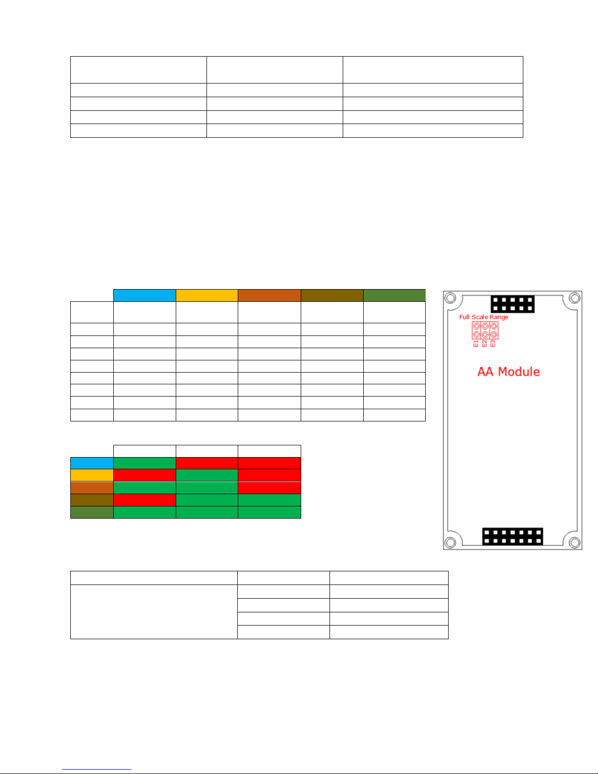
(AA) Acceleration Module Ranges
E1
E2
E3
Range 1
ON
OFF
OFF
Range 2
OFF
ON
OFF
Range 3
ON
ON
OFF
Range 4
OFF
ON
ON
Range 5
ON
ON
ON
Signal Type
Sensor Function
CMCP7504 Terminal
Standard Accelerometer (ICP/IEPE)
N/C
Power
Signal/Pwr (+)
Sig (+)
Com (0V)
Ground (-)
Shield
Shield
Setting The Full Scale Range and Frequency Ranges
The following section will review the available full-scale ranges and frequency ranges available for each
module.
(AA) Acceleration Module
The default factory range is Range 2. With a 100mV/g input, the full-scale range is 10.0g’s
The table below show the full scale range for other input signals.
Full Scale Range Setting
g's g's g's g's g's
Default Frequency Range: 2 to 2,000 Hz
Sensor Wiring
Page 8
STI Vibration Monitoring Inc.
CMCP7504
8
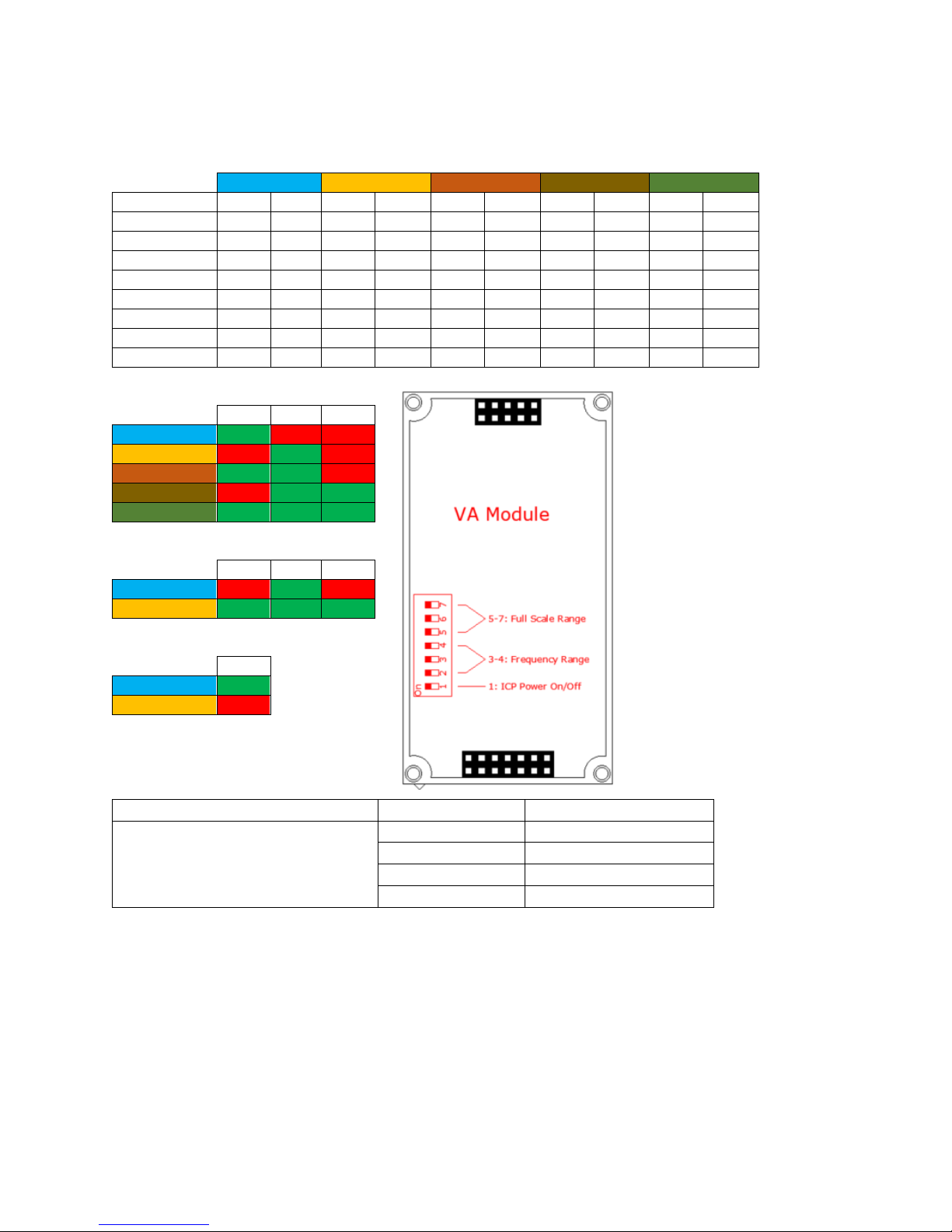
(AV) Velocity Module – Accelerometer Input
Input Sensitivity/Range Table
Range 1
Range 2
Range 3
Range 4
Range 5
Input (mV)
In/Sec
mm/s
In/Sec
mm/s
In/Sec
mm/s
In/Sec
mm/s
In/Sec
mm/s
1,000
0.05
127
0.10
254.00
0.15
381.00
0.20
508.00
0.25
635.00
500
0.10
63.50
0.20
127.00
0.30
190.50
0.40
254.00
0.50
317.50
250
0.20
31.75
0.40
63.50
0.60
95.25
0.80
127.00
1.00
158.75
100
0.50
12.70
1.00
25.40
1.50
38.10
2.00
50.80
2.50
63.50
50
1.00
6.35
2.00
12.70
3.00
19.05
4.00
25.40
5.00
31.75
30
1.67
3.81
3.33
7.62
5.00
11.43
6.67
15.24
8.33
19.05
25
2.00
3.18
4.00
6.35
6.00
9.53
8.00
12.70
10.00
15.88
10
5.00
1.27
10.00
2.54
15.00
3.81
20.00
5.08
25.00
6.35
Full Scale Range Settings
SW 5
SW 6
SW 7
Range 1
ON
OFF
OFF
Range 2
OFF
ON
OFF
Range 3
ON
ON
OFF
` Range 4
OFF
ON
ON
Range 5
ON
ON
ON
Frequency Ranges
SW 2
SW 3
SW 4
10Hz to 1kHz
OFF
ON
OFF
2Hz to 2kHZ
ON
OFF
ON
ICP Power Options
SW 1
On
ON
Off
OFF
Signal Type
Sensor Function
CMCP7504 Terminal
Standard Accelerometer (ICP/IEPE)
N/C
Power
Signal/Pwr (+)
Sig (+)
Com (0V)
Ground (-)
Shield
Shield
The default factory range is Range 2. With a 100mV/g input the full-scale range is 1.00 In/Sec
(25.4mm/Sec)
Sensor Wiring
Page 9

STI Vibration Monitoring Inc.
CMCP7504
9
(VV) Velocity Module Input – Velocity Sensor Input
Input Sensitivity/Range Table
Range 1
Range 2
Range 3
Range 4
Range 5
Input (mV)
In/Sec
mm/s
In/Sec
mm/s
In/Sec
mm/s
In/Sec
mm/s
In/Sec
mm/s
1,000
0.05
127
0.10
254.00
0.15
381.00
0.20
508.00
0.25
635.00
500
0.10
63.50
0.20
127.00
0.30
190.50
0.40
254.00
0.50
317.50
250
0.20
31.75
0.40
63.50
0.60
95.25
0.80
127.00
1.00
158.75
100
0.50
12.70
1.00
25.40
1.50
38.10
2.00
50.80
2.50
63.50
50
1.00
6.35
2.00
12.70
3.00
19.05
4.00
25.40
5.00
31.75
30
1.67
3.81
3.33
7.62
5.00
11.43
6.67
15.24
8.33
19.05
25
2.00
3.18
4.00
6.35
6.00
9.53
8.00
12.70
10.00
15.88
10
5.00
1.27
10.00
2.54
15.00
3.81
20.00
5.08
25.00
6.35
Full Scale Range Jumper Settings
E1
E2
E3
Range 1
ON
OFF
OFF
Range 2
OFF
ON
OFF
Range 3
ON
ON
OFF
` Range 4
OFF
ON
ON
Range 5
ON
ON
ON
Frequency Range Jumper Settings
F1
F2
F3
10Hz to 1kHz
ON
ON
OFF
2Hz to 2kHZ
OFF
ON
ON
Signal Type
Sensor Function
CMCP7504 Terminal
Velocity Transducer (IEPE)
N/C
Power
Signal/Pwr (+)
Sig (+)
Com (0V)
Ground (-)
Shield
Shield
The default factory range is Range 2. With a 100mV/in/sec input the full scale range is 1.00 In/Sec
(25.4mm/Sec)
Sensor Wiring
Page 10

STI Vibration Monitoring Inc.
CMCP7504
10
(RV) Radial Vibration Module– Proximity Probe Input
Input Sensitivity/Range Table
Range 1
Range 2
Range 3
Range 4
Range 5
Input
(mV)
200
5.00
127.00
10.00
254.00
15.00
381.00
20.00
508.00
25.00
635.00
100
10.00
63.50
20.00
127.00
30.00
190.50
40.00
254.00
50.00
317.50
Full Scale Range Jumper Settings
E1
E2
E3
Range 1
ON
OFF
OFF
Range 2
OFF
ON
OFF
Range 3
ON
ON
OFF
` Range 4
OFF
ON
ON
Range 5
ON
ON
ON
Signal Type
Sensor Function
CMCP7504 Terminal
Eddy Current Probe
N/C
Power
Signal/Pwr (+)
Sig (+)
Com (0V)
Ground (-)
Shield
Shield
The default factory range is Range 2. With a 200mV/mil input the full scale range is 10.0 mils (254
microns)
mils microns mils microns mils microns mils microns mils microns
Sensor Wiring
Page 11

STI Vibration Monitoring Inc.
CMCP7504
11
(EV) Enveloped Acceleration Module– Accelerometer Input
Input Sensitivity/Range Table
Range 1
Range 2
Range 3
Input (mV)
gE's
gE's
gE's
1,000
1
2.00
3.00
500
2.00
4.00
6.00
250
4.00
8.00
12.00
100
10.00
30.00
80.00
50
20.00
40.00
60.00
30
33.33
66.67
100.00
25
40.00
80.00
120.00
10
100.00
200.00
300.00
(EV) Acceleration Module Ranges
F1
F2
F3
Range 1
ON
OFF
OFF
Range 2
OFF
ON
OFF
Range 3
OFF
OFF
ON
Signal Type
Sensor Function
CMCP7504 Terminal
Standard Accelerometer (ICP/IEPE)
N/C
Power
Signal/Pwr (+)
Sig (+)
Com (0V)
Ground (-)
Shield
Shield
The default factory range is Range 1. With a 100mV/g input, the full-scale range is 10.0gE.
Sensor Wiring
Page 12

STI Vibration Monitoring Inc.
CMCP7504
12
(AM) Analog Input Module – Voltage or Current
Input Type Table
F1
F2
F3
Software Check
0 to +5VDC
ON
OFF
OFF
NOT CHECKED
0 to -5VDC
OFF
ON
OFF
NOT CHECKED
0 to 20mA
OFF
OFF
ON
NOT CHECKED
+1 to +5VDC
ON
OFF
OFF
CHECKED
-1 to -5VDC
OFF
ON
OFF
CHECKED
4 to 20mA
OFF
OFF
ON
CHECKED
Signal Type
Sensor Function
CMCP7504 Terminal
4-20mA Source
N/C
Power
N/C
Sig (+)
+ Signal
Ground (-)
- Signal
Shield
4-20mA (CMCP7504 Powered)
Signal +
Power
N/C
Sign (+)
N/C
Ground (-)
Shield
Shield
Voltage Source
N/C
Power
N/C
Sig (+)
+ Signal
Ground (-)
- Signal
Shield
Voltage Powered Sensor
+24V
Power
Signal
Sig (+)
Com. (-)
Ground (-)
N/C
Shield
The default factory input is 4-20mA.
Sensor Wiring
(max 35mA)
Page 13

STI Vibration Monitoring Inc.
CMCP7504
13
(TM) Analog Input Module – Voltage or Current
Input Type Table
1 2 3 4 5 6
PT100
ON
ON
OFF
OFF
OFF
OFF
10mV/°C
OFF
OFF
ON
ON
OFF
OFF
The default factory setup is 10mV/°C to accept an input from a dual output accelerometer such as the
CMCP786T.
Sensor Wiring
Page 14

STI Vibration Monitoring Inc.
CMCP7504
14
General Wiring
TS 1
TS 2
Buffered Outputs & Modbus RS485
4-20mA Outputs
1 2 3 4 5 6 7
8 1 2 3 4 5 6 7
8
CH 1 Buffered Out (+)
CH 2 Buffered Out (+)
CH 3 Buffered Out (+)
CH 4 Buffered Out (+)
Buffered Out
RS 485 (+)
RS 485 (Ground)
CH 1 4
20mA Out (+)
CH 1 4
20mA Out (
CH 2 4
20mA Out (+)
CH 2 4
20mA Out (
CH 3 4
20mA Out (+)
CH 3 4
20mA Out (
CH 4 4
20mA Out (+)
CH 4 4
20mA Out (
Buffered Outputs and Analog Outputs
(-)
-)
-)
-)
-)
-
RS 485 (-)
-
-
-
-
-
-
-
Page 15

STI Vibration Monitoring Inc.
CMCP7504
15
Analog Inputs
TS 3
TS 4
Signal Inputs - Channels 1 & 2
Signal Inputs - Channels 3 & 4
1 2 3 4 5 6 7
8 1 2 3 4 5 6 7
8
CH 1 Power
CH 1 Sig (+)
CH 1 Ground (
CH 1 Shield
CH 2 Power
CH 2 Sig (+
CH 2 Ground (
CH 2 Shield
CH 3 Power
CH 3 Sig (+
CH 3 Ground (
CH 3 Shield
CH 4 Power
CH 4 Sig (+
CH 4 Ground (
CH 4 Shield
-)
-)
)
-)
)
-)
)
Page 16

STI Vibration Monitoring Inc.
CMCP7504
16
Alert and Danger Relay Outputs
TS 5
TS 6
Relay Outputs - Channels 1 & 2
Relay Outputs - Channels 3 & 4
1 2 3 4 5 6 7
8 1 2 3 4 5 6 7
8
CH 1 Alert (+)
CH 1 Alert (
CH 1 Danger (+
CH 1 Danger (
CH 2 Alert (+)
CH 2 Alert (
CH 2 Danger (+)
CH 2 Danger (
CH 3 Alert (+)
CH 3 Alert (
CH 3 Danger (+)
CH 3 Danger (
CH 4 Alert (+)
CH 4 Alert (
CH 4 Danger (+)
CH 4 Danger (
)
-)
-)
-)
-)
-)
-)
-)
-)
Page 17

STI Vibration Monitoring Inc.
CMCP7504
17
System OK Relay and System Power
TS 7
OK Relay and Power
1 2 3
4
OK Relay (+)
OK Relay (
DC Power (+)
DC Power (
-)
-)
Page 18

STI Vibration Monitoring Inc.
CMCP7504
18
Configuration Software Overview (MMS Manager)
The MMS Manager software, provided on a USB stick, allows the user to configure the following
parameters;
• COM Port Setting for RS232 Communications
• Transferring or Downloading the CMCP7504 Configuration File
• Measurement Point Name
• Input Signal Selection
• Engineering Unit Selection
• Alarm and Danger Alarm Limits
• Alarm Operation (Latching or Non-Latching)
• Alarm Time Delay
• Full Scale (Min/Max) Range
• Bar graph View Scale
• 4-20mA Output Scaling
• 4-20mA Offset
The screenshots below will show how the MMS Software Manager is used to program the CMCP7504.
Measurement Point Name
The user can input any “Point Name” desired through abbreviations or full words, however, spacing is
limited to 12 characters.
Input Signal Type
The input signal type is determined by the input module type. Verify the setup screen is programmed in
the same order as the input modules are installed on the main board.
Page 19

STI Vibration Monitoring Inc.
CMCP7504
19
Engineering Units
The engineering units drop down box allows the user to set the desired units in English or Metric. The
selected units should be set according to the layout of the sensor input modules.
Alarm Level Setup and Relay State
This section allows the user to set both the Alert and Danger setpoints along with the time delay and relay
operation.
Relay Operating Type
When the relays are set to non-latching, the relays will automatically clear once the amplitude drops
below the programmed threshold. When the relays are set to latching, the relays will hold their state until
the reset button is depressed.
Page 20

STI Vibration Monitoring Inc.
CMCP7504
20
Bypass
When the relays are set to bypass, the relays will not change state when an alarm threshold is reached.
Relay NE/NDE
When set to NE, the relays are normally energized (relay opens on alarm). When set to NDE, the relays
are normally de-energized (relay closes on alarm)
Relay Delay Time (ms)
A time delay of 0 to 10,000 milliseconds (ms) can be added to each alarm
Signal Scaling
The Signal Scaling section is used to set the CMCP7504’s analog outputs to match the configuration of the
sensor input module and display. The Full Scale Min and Full Scale Max should be set according to the
range selected on the sensor input module, for example, if the input module is set for a 0 to 2.00 in/sec
range the Signal Full Scale Max should be set for 2.00 and Signal Full Scale Min to 0.00.
Page 21

STI Vibration Monitoring Inc.
CMCP7504
21
View Scale
The View Scale is used to adjust the CMCP7504’s bar-graph display. The View Scale should match the
sensor input modules range or it can be set to display over-range readings as well.
4-20mA Offset
The 4-20mA offset is calibrated by the factory at the time of shipment and should not be changed unless
advised by the factory.
Page 22

STI Vibration Monitoring Inc.
CMCP7504
22
Uploading Configuration Files (Set Data)
Property
Value Range
Default Settings
Modbus Mode
RTU (binary Range)
Modbus Address
1 thru 247
1
Hardware Interface
RS485 (Half Duplex / Two Wire)
Baud Rate
4800, 9600, 19200
9600
Data Bits
8
Stop Bits
1 or 2
1
Parity
None, Odd or Even
None
Modbus Function Code
FC04 (Read)
Retries
3
After all measurement parameters have been selected, click “Send Set Ch1” and the parameters will be
uploaded to the CMCP7504. Click the remaining Send Set buttons for channels 2-4. If desired, a single
channel may be configured or changed. Verify that the CMCP7504 shows the current updates and
disconnect USB cable.
Saving the Configuration File (Save File)
Click “Save File” to store a copy of the configuration file on your local drive.
Uploading Configuration File (Load File)
If a local copy of the configuration file cannot be found, connect a USB cable to the CMCP7504 and click
“Load File”. A copy of the existing program on the CMCP7504 will be uploaded to your computer and can
be saved to your local drive.
Configuring the Modbus RS485 Output
The CMCP7504 provides a two wire (half duplex) Modbus RS485 output for connecting to a PLC, DCS,
SCADA or other system. The Modbus settings can be found in the MMS Manager. The default Baud Rate
is 9600 and the Default Slave ID Number is 1. The Modbus settings can be changed using the MMS
Manager. Multiple CMCP7504’s can be connected to the same RS485 line by changing the Slave ID
Number.
Modbus Communications Setup
Page 23

STI Vibration Monitoring Inc.
CMCP7504
23
Technical Specifications
Power Requirements
Supply Voltage: 90 to 240VAC to Internal Power Supply 24VDC Direct to Main Board
Power Consumption: 30W
Relay Rating: 1A @ 250VAC
Input Signal
Sensor Types: Accelerometers, Velocity Transducers, Eddy Current Probes, Analog Output
Frequency Range: Jumper Selectable
Sensor OK: Continuous Monitoring of BOV or Gap Voltage
If voltage exceeds the limit the 4-20mA will drop to 2mA
Output Signal
Buffered Output: Per Channel, BNC and Terminal Block Output
Sensitivity Same as Sensor
Accuracy: +/-1%
Analog Output: Isolated 4-20mA
Environmental
Operating Temperature: -20 to 80°C (-4 to 176°F)
Storage Temperature: -55 to 125°C (-67 to 257°F)
Humidity: 0-90% Relative Humidity, Non-Condensing
IP Rating: IP65
Mechanical
Weight: 6.5 lb (2.95kg)
Color: Power Coated Gray
Dimensions: 10.24” x 6.3” x 3.54” (260x160x90mm)
Page 24

STI Vibration Monitoring Inc.
CMCP7504
24
Sample Wiring Diagrams
IEPE Accelerometer or Velocity Transducer Dual Output Accelerometer with Temperature
Eddy Current Probe
Page 25

STI Vibration Monitoring Inc.
CMCP7504
25
100 Ohm Platinum RTD (PT100)
4-20mA Loop Powered Sensor (2 Wire) 4-20mA Source (3 Wire)
 Loading...