

Page 1
CMCP7500MMS
Machine Monitoring System
Configuration and Setup
STI Vibration Monitoring, Inc. Page 1
Page 2

Contents
Software Configuration and Setup ............................................................................................................................................................................ 3
Channel Configuration and Setup: ....................................................................................................................................................................... 3
On/OFF: (Channel, On/Off) ............................................................................................................................................................................. 4
Header: (Channel Header, 12 Characters) ...................................................................................................................................................... 4
Cust Tag: (Customer Tag, 7 Characters) .......................................................................................................................................................... 4
Ch. EU: (Channel Engineering Units, 4 Characters) ......................................................................................................................................... 4
Ch. Min: (Channel Minimum Value, -999.00 to 999.00) ................................................................................................................................. 4
Ch. Max: (Channel Maximum Value, -999.00 to 999.00) ................................................................................................................................ 5
Enable Hi: (Enable Hi Alarms, Yes/No) ............................................................................................................................................................ 5
Hi Alert: (High Alert Value or Hi Alarm, Min/Max) .......................................................................................................................................... 5
HIHi Dgr: (High Danger or HiHi Alarm, Min/Max) ........................................................................................................................................... 5
Enable Lo: (Enable Low Alarms, Yes/No) ........................................................................................................................................................ 5
Lo Alert: (Low Alert or Lo Alarm, Min/Max) .................................................................................................................................................... 5
LoLo Dgr: (Low Danger or LoLo Alarm, Min/Max) ........................................................................................................................................... 5
Alert Relay: (Assigned Alert Relay, 0 to 12) .................................................................................................................................................... 6
Dgr. Relay: (Assigned Danger Relay, 0-12) ...................................................................................................................................................... 6
System Setup: ...................................................................................................................................................................................................... 6
Adjust Date/Time: .......................................................................................................................................................................................... 6
Company Name: (30 Characters) .................................................................................................................................................................... 6
Company Location: (30 Characters) ................................................................................................................................................................ 6
Data Logger Status: (On/Off) .......................................................................................................................................................................... 6
Hardware Configuration ............................................................................................................................................................................................ 7
General Description: ............................................................................................................................................................................................ 7
Front Panel Layout: .............................................................................................................................................................................................. 7
Back Panel Layout: ............................................................................................................................................................................................... 7
Block Diagram: ..................................................................................................................................................................................................... 8
BNC Buffered Output Boards: .............................................................................................................................................................................. 9
Transmitter or Signal Input Card Board: .............................................................................................................................................................. 9
Field Wiring Board: ............................................................................................................................................................................................ 10
Transmitters and Signal Input Cards: ................................................................................................................................................................. 11
Power Supplies: ................................................................................................................................................................................................. 11
Field IO: .............................................................................................................................................................................................................. 11
Color Touchscreen HMI Computer:.................................................................................................................................................................... 12
Dimensions: ....................................................................................................................................................................................................... 12
Sensor Wiring:.................................................................................................................................................................................................... 13
STI Vibration Monitoring, Inc. Page 2
Page 3
Software Configuration and Setup
Channel Configuration and Setup:
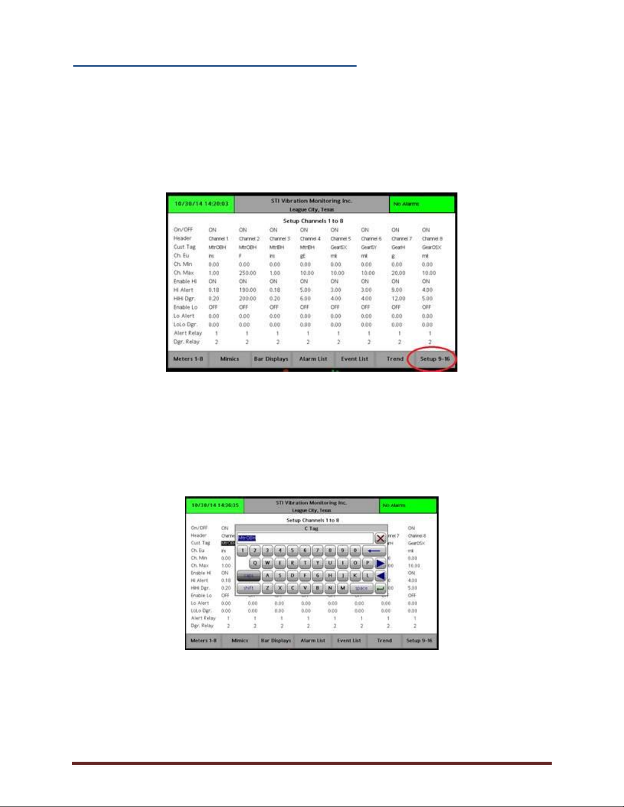
Programming Channels using the CMCP7500 Software is simple and accomplished by using
the Setup Screen which is accessible by pressing or touching the bottom right “Setup”
button on the touch screen and entering the system password if requested.
Figure 1: Channel Setup
Channels can be turned off or on, ranges selected, alarm values set, tags entered and
relays assigned from the Setup Screen. Simply touch the value you want to change and a
Pop Up “Alpha” or “Numeric” entry window will appear. Enter the new value keeping in mind
the constraints listed below and press return.
Figure 2: Alpha/Numeric Pop-Up Window
STI Vibration Monitoring, Inc. Page 3
Page 4
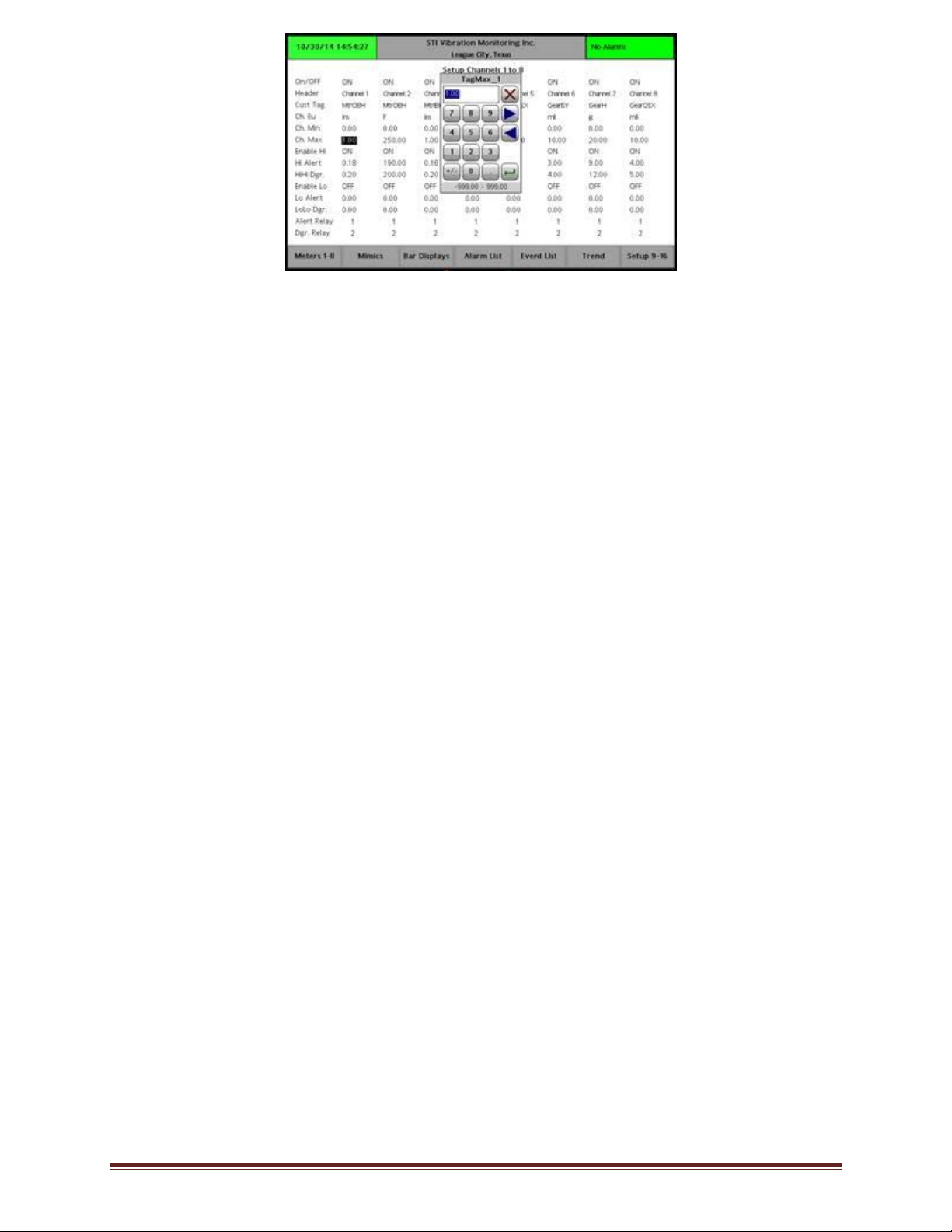
Figure 3: Numeric Pop-Up Window
There are Fourteen (14) items that need to be entered to setup each channel as shown on
left side of screen. They are as follows:
On/OFF: (Channel, On/Off)
Each Channel may be turned “Off” or “On”. When Off the Meters and Bargraphs will
not display that channel. Alarming and trending will also be disabled.
Header: (Channel Header, 12 Characters)
The Header field contains up to 12 Alpha Numeric Characters and is completely
editable. We use this field for Channel Numbers and recommend you leave them as
such.
Cust Tag: (Customer Tag, 7 Characters)
The Customer Tag field is completely editable and contains up to 7 Alpha Numeric
Characters of your choice. An example is “MtrOBH” for Motor Outboard Horizontal.
Ch. EU: (Channel Engineering Units, 4 Characters)
Channel Engineering Units can contain up to 4 Alpha Numeric Characters of your
choice and is used to attach engineering units to that channels value. Examples are,
mils, Vel, ins, gE, F, C, g’s or um, mm, mms, Vel, gE or g’s.
Ch. Min: (Channel Minimum Value, -999.00 to 999.00)
Channel Minimum Value determines the lower value of the display range. It will also
determine the lower range in which alarms can be set. This value is normally but not
always “0” and must match the lower range of the Channel Input Card you have
selected for that channel. Examples are: 0-1.00 in/sec, 0-10.0 mils, -40.0-0-40.0
Thrust, 0 – 300 F, 0-25 mm/sec, etc.
STI Vibration Monitoring, Inc. Page 4
Page 5

Ch. Max: (Channel Maximum Value, -999.00 to 999.00)
Channel Maximum Value determines the upper value of the display range. It will also
determine the upper range in which alarms can be set. This must match the lower
range of the Channel Input Card you have selected for that channel. Examples are:
0-1.00 in/sec, 0-10.0 mils, -40.0-0-40.0 Thrust, 0 – 300 F, 0-25 mm/sec, etc.
Enable Hi: (Enable Hi Alarms, Yes/No)
Enable Hi Alarms allow you to turn on or off the two (2) high alarms usually known
as Alert and Danger (Hi and HIHi). When Off Upper Alarms are disabled and no
alarming will occur.
Hi Alert: (High Alert Value or Hi Alarm, Min/Max)
Allows you to enter the Alert (Hi) value for this channel. Your entry will be limited by
the Channel min/max scale you have previously selected. Value entered must be
between the Channel Min and Max entered for this Channel.
HIHi Dgr: (High Danger or HiHi Alarm, Min/Max)
Allows you to enter the Danger (HiHi) value for this channel. Your entry will be
limited by the Channel min/max scale you have previously selected. Value entered
must be between the Channel Min and Max entered for this Channel.
Enable Lo: (Enable Low Alarms, Yes/No)
Enable Low Alarms allow you to turn on or off the two (2) low alarms usually known
as Low Alert and Low Danger (Lo and LoLo). When Off Lower Alarms are disabled
and no low alarming will occur. Low alarms are most commonly used for Thrust
Position measurement and low oil temperatures.
Lo Alert: (Low Alert or Lo Alarm, Min/Max)
Allows you to enter the Low Alert (Lo) value for this channel. Your entry will be
limited by the Channel min/max scale you have previously selected. Value entered
must be between the Channel Min and Max entered for this Channel.
LoLo Dgr: (Low Danger or LoLo Alarm, Min/Max)
Allows you to enter the Low Danger (LoLo) value for this channel. Your entry will be
limited by the Channel min/max scale you have previously selected. Value entered
must be between the Channel Min and Max entered for this Channel.
STI Vibration Monitoring, Inc. Page 5
Page 6

Alert Relay: (Assigned Alert Relay, 0 to 12)
This Alert Relay entry assigns which relay number will be triggered by this Channels
Alert (Hi) or Low Alert Alarms (Lo). Be sure your relay entry is correct for the size
system you purchased. Multiple channels may select the same relay.
Dgr. Relay: (Assigned Danger Relay, 0-12)
This Danger Relay entry assigns which relay number will be triggered by this
Channels Danger (HiHi) or Low Danger Alarm (LoLo). Be sure your relay entry is
correct for the size system you purchased. Multiple channels may select the same
relay.
System Setup:
The first step to configure your CMCP7500 Software is to setup the System Information
which includes basic information such as date and time, company name and location. The
Data Logger may also be turned on and off on this page. To access System Information
simply press the “Setup” Button on the Touchscreen until the Setup System screen appears.
Adjust Date/Time:
If the CMCP7500 is not receiving date and time over an network then it will be
necessary to enter both the current date and time using the Popup Screen that
appears when touched. Date and Time Tags are used on all Alarm Lists and Trends.
Company Name: (30 Characters)
Company Name can include up to 30 Characters of your choice. You may also use
this field to identify a particular machine id, unit or location. Entry has no effect on
system function.
Company Location: (30 Characters)
Company Location can include up to 30 Characters of your choice. You may also use
this field to identify a particular machine id, unit or location. Entry has no effect on
system function.
Data Logger Status: (On/Off)
Data Logger Status allows you to turn On or Off Data Logging. While usually left On
you may desire to turn it Off while the machine is not operating or being rebuilt.
Turning Off will affect the Trend Function.
STI Vibration Monitoring, Inc. Page 6
Page 7

Hardware Configuration
General Description:
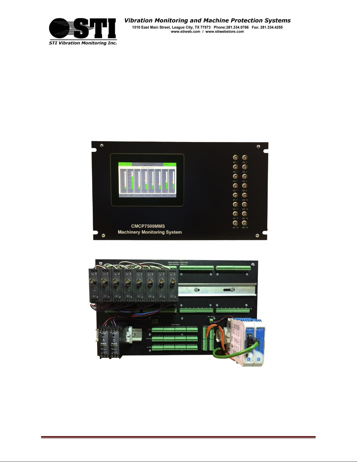
The CMCP7500MMS 19” EIA Rack Mounted Machinery Monitoring System is designed to work with STI’s
line of Vibration, Thrust, Temperature and TSI (Turbine Supervisory Instrumentation) Din Rail Mounted
Transmitters or Signal Input Cards. The CMCP7500MMS is ordered in blocks of 8 Channels for a
maximum of 32 Channels if CMCP700 Series Slim line Transmitters are used. If CMCP500 Series
Transmitters are used as Signal Input Cards the maximum is 16 Channels. Total DIN Rail mounting space
allocated for Signal Input Cards is 16” (406.2 mm). When Signal Input Cards are ordered with the
CMCP7500MMS STI will complete the installation of the Transmitters and will perform a full Factory
Acceptance Test of the complete integrated system.
Front Panel Layout:
Back Panel Layout:
Figure 4: Front Panel
Figure 5: Back Panel
STI Vibration Monitoring, Inc. Page 7
Page 8

Block Diagram:
The following Block Diagram shows hoe the CMCP7500MMS is populated to be a 8, 16, 24, 0r 32
Channel Base System. The actual channels of monitoring are determined by the number of Transmitters
or Signal Input Cards purchased. The CMCP7500MMS can be expanded in the future up to a total of 32
Channels.
Figure 6: Block Diagram
STI Vibration Monitoring, Inc. Page 8
Page 9

BNC Buffered Output Boards:
BNC or Buffered Output Boards are preinstalled in Blocks of 8 Channels up to a total of 32 Channels and
connect to the Transmitter or Signal Input Card Board via Ribbon Cables. Each Transmitter or Signal
Input Board will be provided with a BNC Board. The BNC Board allows the connection of Analyzers from
the front of the CMCP7500MMS using a standard BNC Connectors. No user wiring is required and if a
BNC Connector is damaged it may be easily replaced.
Figure 7: BNC Board
Transmitter or Signal Input Card Board:
The CMCP7500MMS Transmitter or Signal Input Boards are preinstalled in blocks of 8 Channels for a
total of up to 4 boards for 32 total channels. They are mounted on the inside of the back plate so only
the terminals are visible from the back. This is where STI’s CMCP500 or CMCP700 Series Transmitters
interface to the CMCP7500MMS HMI Based Monitoring System. There are a total of six (6) terminal
positions for each Transmitter. Three (3) above and three (3) below. If you ordered Transmitters or
Signal Input Cards when ordering all integration and testing will be completed. These instructions will
allow you to add additional channels when required. The Transmitter or Signal Input Boards connect via
ribbon cables to both the Buffered Output Board and the Field Wiring Board.
STI Vibration Monitoring, Inc. Page 9
Page 10

Upper Three (3) Terminal Connections
S C B
Signal
Common
Buffered Output
Lower Three (3) Terminal Connections
V C O
+24 VDC
Common
4-20 mA Output
Field Wiring Board:
Figure 8: Transmitter Board
Transmitter Board Terminal Connection Key:
The Field Wiring Board is where all field sensors are connected to the CMCP7500MMS System. There is
only one size of Field Wiring Board and it may be connected to one (1) or up to four (4) Transmitter
Boards for a total of up to 32 Channels. The Field Wiring Board allows the connection of both IEPE
Powered Accelerometers and -24 VDC Powered Proximity Systems.
IEPE Accelerometers field wiring connects to Signal and Common (Constant Current Power is provided
on Signal Terminal) Proximity Probe Systems field wiring connects to Signal, Common and -24 VDC
STI Vibration Monitoring, Inc. Page 10
Page 11

Part Number
8 Channel
16 Channel
24 Channel
32 Channel
CMCP515-1250
2
CMCP515-2080
2
CMCP515-4200
2
2
Part Number
8 Channel
16 Channel
24 Channel
32 Channel
CMCP-XT-1211 8 Ch. AI
1 1
CMCP-XT-1231 16 Ch. AI
1 1
2
CMCP-XT-1111 16 Ch. DO
1 1 1
1
CMCP-XRA-MRNO Relay Mod.
1 1 1
1
Figure 9: Field Wiring Board
Transmitters and Signal Input Cards:
Due to the many models available current data sheets and detailed manuals for STI CMCP500 and
CMCP700 Series Transmitters and Signal Input Cards are available by downloading from STI’s web site at
www.stiweb.com.
Power Supplies:
Power Supplies size varies depending on CMCP7500 MMS Channel Quantity ordered. Both a +24VDC
and -24 VDC Power Supplies (for proximity systems) are provided. Quantity and Model Number are:
Field IO:
Current Data Sheets and Detailed Manuals for the Field IO and Relay Modules are available by
downloading from STI’s web site at www.stiweb.com. Part Numbers and quantities are as follows.
STI Vibration Monitoring, Inc. Page 11
Page 12

Color Touchscreen HMI Computer:
Current Data Sheets and Detailed Manuals for the standard G7 Color Touchscreen HMI Computer are
available by downloading from STI’s web site at www.stiweb.com .
Dimensions:
Figure 10 Front Panel Dimensions
Figure 11 Back Panel Dimensions
STI Vibration Monitoring, Inc. Page 12
Page 13

Sensor Wiring:
Figure 13 Typical Proximity System Wiring
Figure 12 Typical Accelerometer Wiring
STI Vibration Monitoring, Inc. Page 13
 Loading...