

STI CLIMBER PR-8623 Owner's Manual
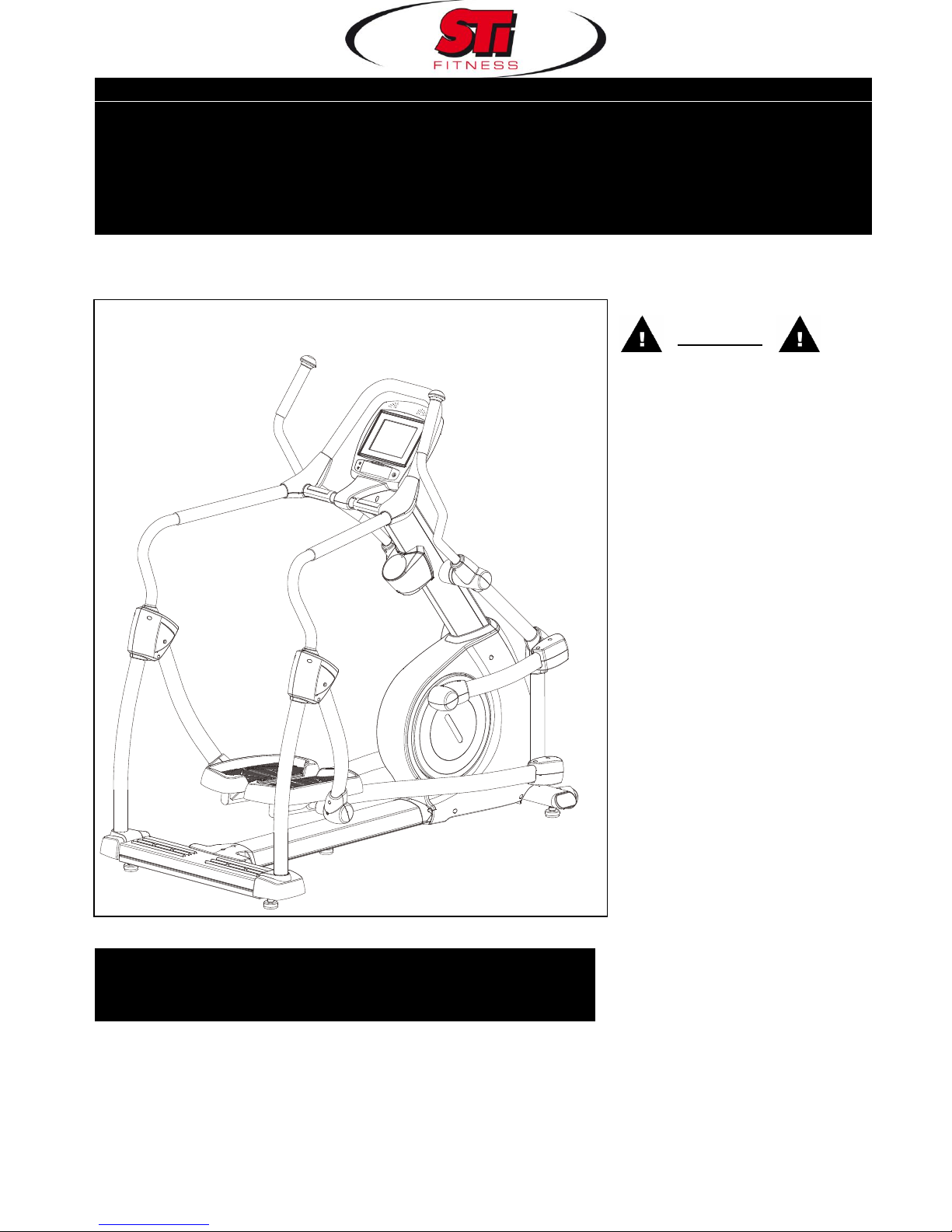
PR-8623
Product May Vary Slightly From Picture.
v.II
Exercise can present a health
risk. Consult a physician before
beginning any exercise program
with this equipment.
If you feel faint or dizzy,
immediately discontinue use of
this equipment. Serious bodily
injury can occur if this
equipment is not assembled
and used correctly. Serious
bodily injury can also occur if all
instructions are not followed.
Keep children and pets away
from equipment when in use.
Always make sure all bolts and
nuts are tightened prior to each
use. Follow all safety
instructions in this manual.
WARNING
CAUTION:
Weight on this product should not exceed 181 kgs/ 400 lbs
MADE IN TAIWAN
OWNER’S MANUAL
CLIMBER

1
SAFETY INSTRUCTIONS
WARNING: To reduce the risk of serious injury, read the following Safety Instructions before using the
Climber.
1. Read all warnings posted on the Climber.
2. Read this Owner's Manual and follow it carefully before using the Climber. Make sure that it is properly assembled and
tightened before use.
3. We recommend that two people be available for assembly of this product.
4. Keep children away from the Climber. Do not allow children to use or play on the Climber. Keep children and pets away
from the Climber when it is in use.
5. It is recommended that you place this exercise equipment on an equipment mat.
6. Set up and operate the Climber on a solid level surface. Do not position the Climber on loose rugs or uneven surfaces.
7. Inspect the Climber for worn or loose components prior to use.
8. Tighten/replace any loose or worn components prior to using the Climber.
9. Consult a physician prior to commencing an exercise program. If, at any time during exercise, you feel faint, dizzy, or
experience pain, stop and consult your physician.
10. Follow your physician's recommendations in developing your own personal fitness program.
11. Always choose the workout which best fits your physical strength and flexibility level. Know your limits and train within them.
Always use common sense when exercising.
12. Before using this product, please consult your personal physician for a complete physical examination.
13. Do not wear loose or dangling clothing while using the Climber.
14. Never exercise in bare feet or socks; always wear correct footwear, such as running, walking, or cross-training shoes.
15. Be careful to maintain your balance while using, mounting, dismounting, or assembling the Climber, loss of balance may
result in a fall and serious bodily injury.
16. Keep both feet firmly and securely on the Foot Pedals while exercising.
17. The Climber should not be used by persons weighing over 400 pounds /181 kgs.
18. The Climber should be used by only one person at a time.
19. Use two people to assemble and move the Climber.
20. Maintenance: Replace the defective components immediately and/or keep the equipment out of use until repair the
equipment completely.
21. Make sure that adequate space is available for access to and passage around the Climber; keep at least a distance of 1
meter from any obstruction object while using the machine.
22. The Climber is well-suited to commercial usage.
WARNING: Before starting any exercise or conditioning program you should consult with your personal physician to see if
you require a complete physical exam. This is especially important if you are over the age of 35, have never exercised before,
are pregnant, or suffer from any illness.
READ AND FOLLOW THE SAFETY PRECAUTIONS. FAILURE TO FOLLOW THESE
INSTRUCTIONS CAN RESULT IN SERIOUS BODILY INJURY.
2
“BEFORE YOU BEGIN”
/Thank you for choosing the Climber. We take great
pride in producing this quality product and hope it will
provide many hours of quality exercise to make you
feel better, look better and enjoy life to its fullest.
Yes, it's a proven fact that a regular exercise
program can improve your physical and mental health.
Too often, our busy lifestyles limit our time and
opportunity to exercise. The Climber provides a
convenient and simple method to begin your assault
on getting your body in shape and achieving a
happier and healthier lifestyle.
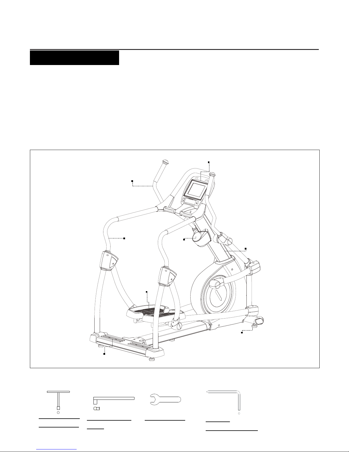
Before reading further, please review the drawing
below and familiarize yourself with the parts that are
labeled. Read this manual carefully before using the
Climber.
THE FOLLOWING TOOLS ARE INCLUDED FOR ASSEMBLY:
T-HAND SOCKET
WRENCH (17mm)
SOCKET WRENCH
(13mm)
WRENCH (17mm)
PHILLIPS
SCREWDRIVER (6mm)
Console
Stationary
Handrail
Upright Post
Accessory
Tray
Dual
Handlebar
Leveler
Pedal
Non-Slip Pad
3
“HARDWARE IDENTIFICATION CHART”
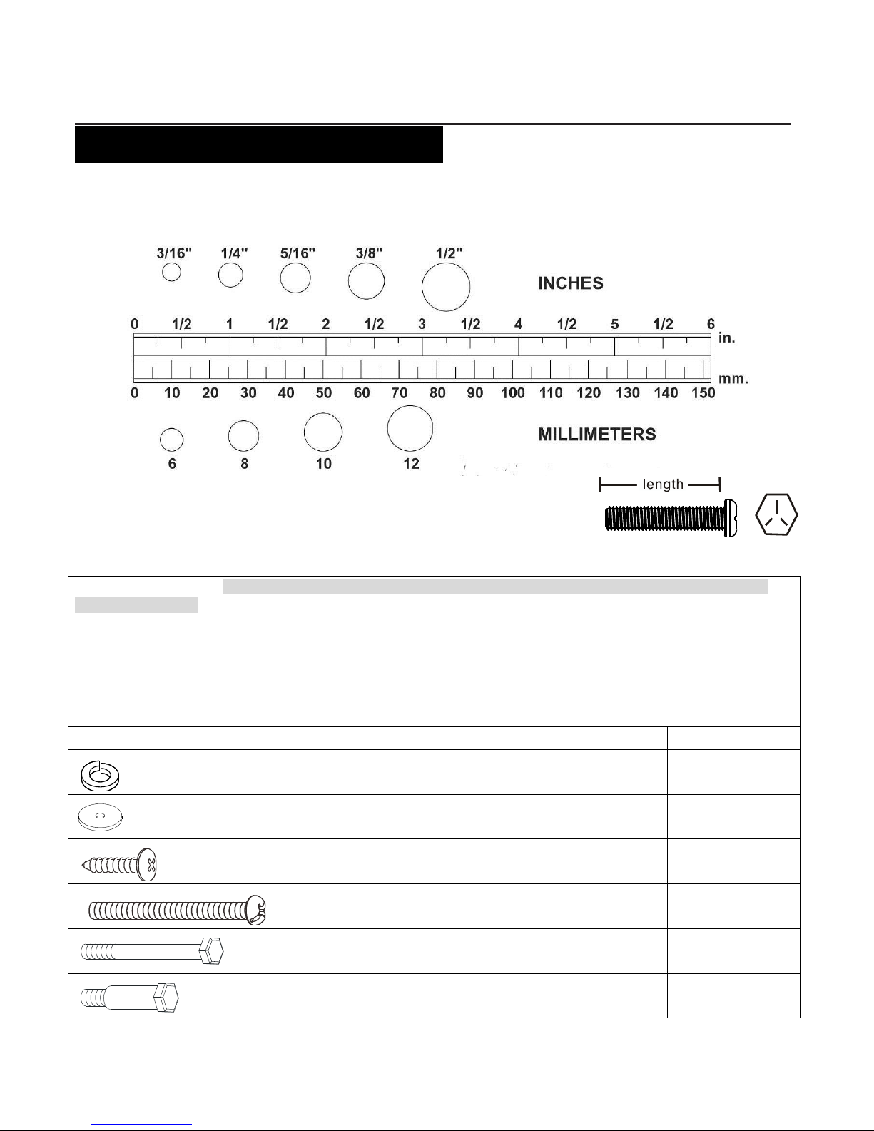
Unpack the box in a clear area. Use the List of Hardware below to check the contents of the hardware kit. This chart is
provided to help identify the hardware used in the assembly process. Place the washers, the end of bolts, or screws on the
circles to check for the correct diameter. Use the ruler to check the length of the bolts and screws.
NOTICE: The length of all bolts and screws except those with flat heads is
measured from below the head to the end of the bolt or screw. Flat head
bolts and screws are measured from the top of the head to the end of the
bolt or screw.
After unpacking the unit, you will notice that the package includes 2 bags of hardware (HARDWARE KIT A and
HARDWARE KIT B).
Assembly Step 2, 4, 9, 10: Using HARDWARE KIT A
Assembly Step 11, 12, 14, 15, 16, 17, 19, 20: Using HARDWARE KIT B
Note:
a. Please review below to know the content of each hardware kit (A and B)
b. Some small parts may have been pre-attached for shipping. If a part is not in the hardware bag, check to see if it has
been pre-assembled
HARDWARE KIT A
Part No. and Description
Q’TY
111 Lock Washer (M8)
2
114 Washer (8x38x2.0t)
2
118 Screw, Round Head (M4x12mm)
4
126 Bolt, Round Head (M5×p0.8×30mm)
2
141 Bolt, Hex Head (M8xp1.25x65mm)
2
143 Bolt, Hex Head (M10xp1.5x50mm)
2
4
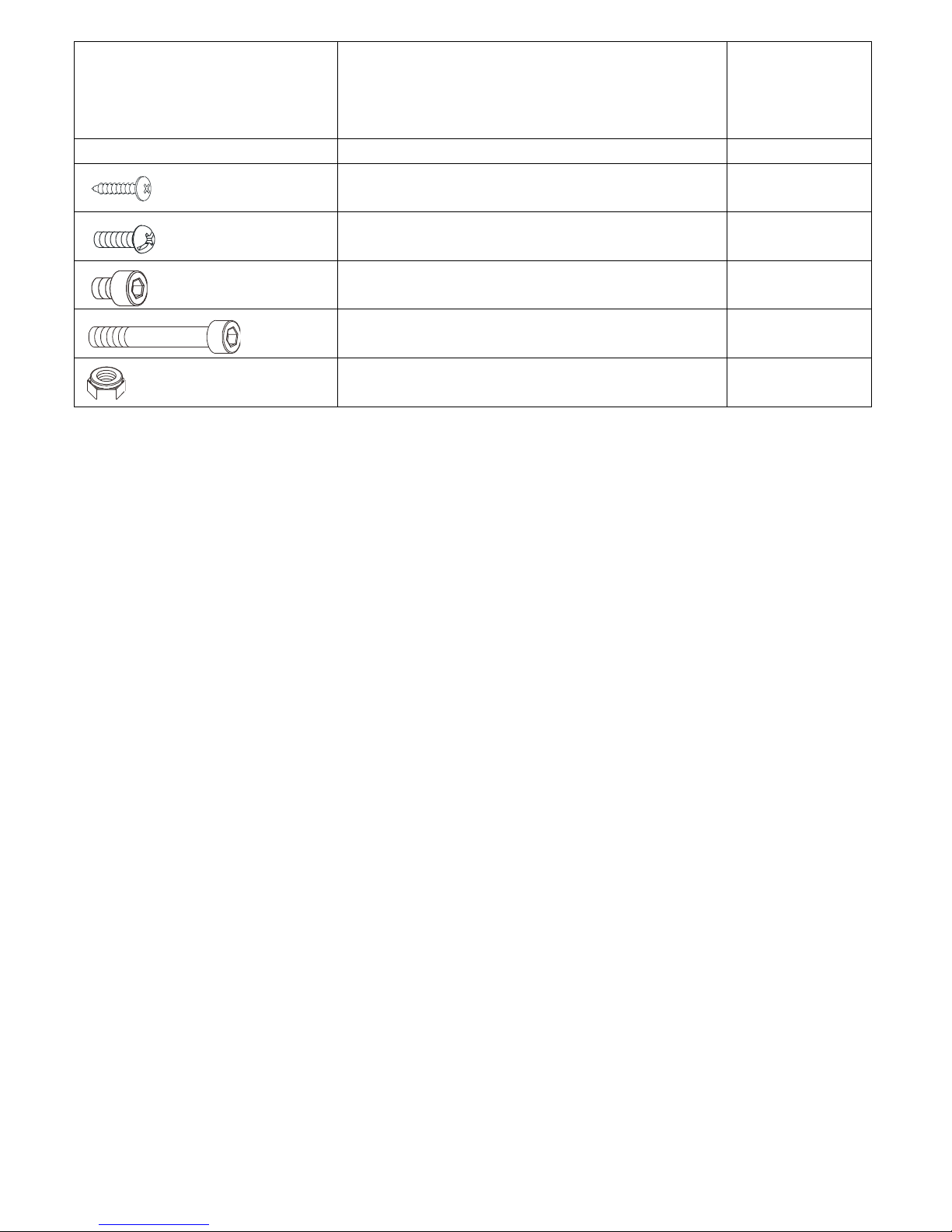
HARDWARE KIT B
Part No. and Description
Q’TY
121 Self-Tapping Screw, Flat Head (M4x20mm)
11 125 Bolt, Round Head (M5xp0.8x15mm)
22 134 Bolt, Socket Head (M8xp1.25x10mm)
8 146 Bolt, Socket Head (M10xp1.5x110mm)
2 154 Nylon Nut (M10xp1.5)
2
5
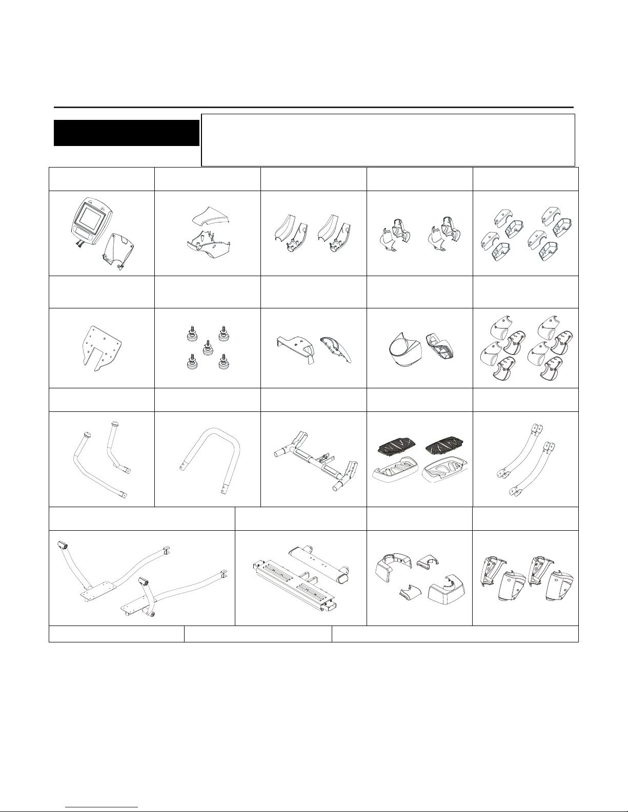
“ASSEMBLY PARTS”
Console & Console
Bracket
Handlebar
Decoration Cover
Top & Bottom
Handrail Cover
Rotator Cuff –
Pivoting Arm
Front Linkage Cover
Console Fixed Plate
Leveler
Rear Base Frame
Cover & Front
Decoration Covers
Accessory Tray &
Support Pad
Rear Rotation Cover
Upper Handlebar
U-Shaped Handlebar
U-Shaped Handlebar
Stand
Pedal &
Non-Slip Pad
Pivoting Arm
Linkage
Pedal Support Arm
Front & Rear Stabilizer
Bottom Handrail
Decoration Cover
Swing Linkage
Cover
Upright Post
Long Stationary Handrail
Main Frame
Unpack the box in a clear area. Follow the List of Assembly Parts below to check
and make sure all assembly parts are present and in good condition. Do not dispose
of the packing material until the assembly process is completed. Assembly tools and
hardware kit have included for you to use when assembling the product
6
“ASSEMBLY INSTRUCTIONS”
Place all parts from the box in a cleared area and position them on the floor in front of you. Remove all packing materials
from your area and place them back into the box. Do not dispose of the packing materials until assembly is completed.
Read each step carefully before beginning.
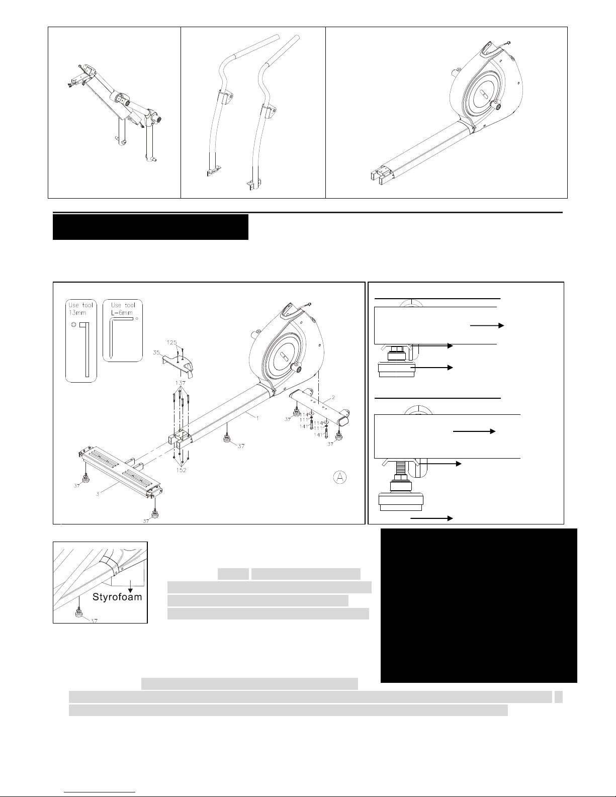
STEP 1 – Leveler Assembly
a. Follow the drawing on the left to tighten one
Leveler (37) under the middle of the Main
Frame (1.) NOTE: It will be easier to attach
the Leveler (37) under the Main Frame (1) by
placing one Styrofoam (or any stationary
object) under one side of the Main Frame (1).
b. Attach 4pcs Levelers (37) to the Front Stabilizer (2) and the Rear
Stabilizer (3).
c. Be sure to tighten the Levelers (37) securely against the Stabilizers
(2, 3) until screw lines are eliminated as the drawing 1 shown on the
top right corner. NOTE: In order to assemble the Stabilizer (2, 3)
smoothly, it is suggested to place one Styrofoam (or any stationary object) under one side of the Main Frame. If
the item is not level, review the LEVELING NOTE on the above right side to level the Levelers (37).
STEP 2 – Front & Rear Stabilizer & Rear Base Frame Cover Assembly
Detailed Lever- drawing 1
Detailed Lever- drawing 2
LEVELING NOTE: After placing the
equipment in the intended location for use,
check the stability of the equipment. If the
equipment is not level, reviewing the
following direction:
Loosen the Leveler (37) to make the
Adjustment Plate become less tight.
Adjust the Leveler (37) for leveling.
Tighten the Adjustment Plate securely
against the Stabilizer to lock the Leveler (37)
in stable position as the above drawing 2
shown.
Stabilizer
Adjustment Plate
Leveler (37)
Stabilizer
Leveler (37)
Adjustment Plate

7
a. Attach the Front Stabilizer (2) onto the Main Frame (1) and secure with 2pcs
Washers (8x38x2.0t)(114), 2pcs Lock Washers (M8)(111) and 2pcs Bolts, Hex
Head (M8xp1.25x65mm)(141).
b. NOTE: 4pcs Bolt, Socket Head (M8×p1.25×65mm)(137) and Nylon Nut
(M8xp1.25)(152) are attached on the front of the Rear Stabilizer (3), and 2pcs Bolts,
Round Head (M5×p0.8×15mm)(125) are attached on the rear of the Main Frame (1)
as the left draft shown.
c. Remove 4pcs Bolt, Socket Head (M8×p1.25×65mm)(137) and Nylon Nut
(M8xp1.25)(152) from the front of the Rear Stabilizer (3). And remove 2pcs Bolts,
Round Head (M5×p0.8×15mm)(125) from the rear of the Main Frame (1).
d. Attach the Rear Stabilizer (3) to the Main Frame (1) and secure with 4pcs Bolt, Socket Head (M8×p1.25×65mm)(137)
and Nylon Nut (M8xp1.25)(152).
e. Attach the Rear Base Frame Cover (35) to the rear of the Main Frame (1) and secure with 2pcs Bolts, Round Head
(M5×p0.8×15mm)(125).
“ASSEMBLY INSTRUCTIONS”
STEP 3 – Connection Wire Assembly
CAUTION: Be careful not to damage the Wires (158, 159) while assembling Step 3 & 4.
Attach the Middle Connection Wire (158) into the Lower Connection Wire (159). NOTE: Be careful not to pinch the
wires.
8
STEP 4 – Upright Post Assembly
a. 2pcs Thin Nylock Nuts (M10xp1.5)(153) have preassembled into the front of the Main Frame (1) as the following
drawing shows (they will not be tight, so that slotted bracket of the upright post will slide between the nut and the
frame).
b. Insert the Upright Post (4) into the Main Frame (1) and secure with 2pcs Bolts, Hex Head (M10xp1.5x50mm)(143)
by using the T-HEAD SOCKET WRENCH as shown.
NOTE: Please do not fully tighten Bolts (143) or Nuts (153) until Step. 10 has been
COMPLETED.
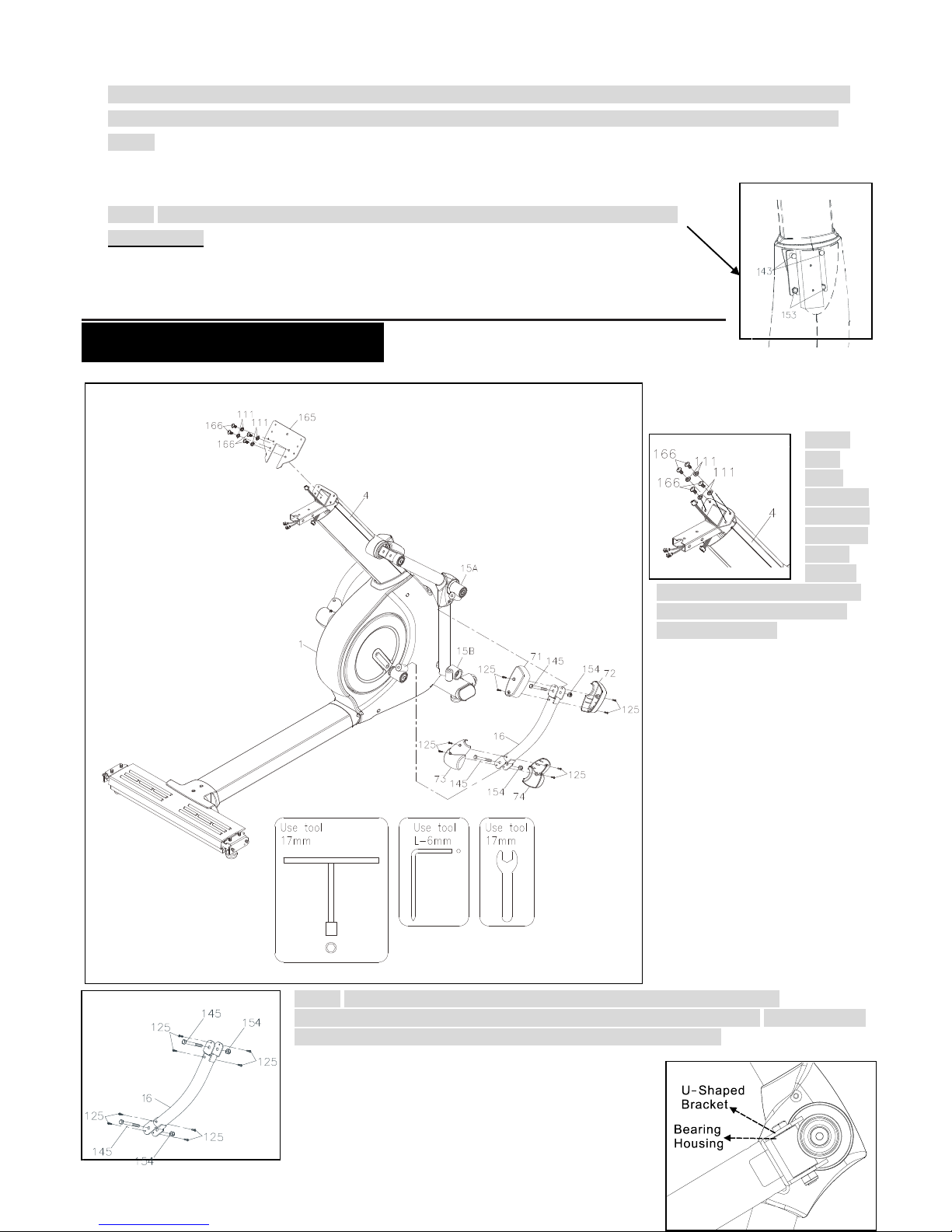
“ASSEMBLY INSTRUCTIONS”
STEP 5 – Console
Fixed Plate Assembly
NOTE:
4pcs
Lock
Washers
(M8)(111)
and 4pcs
Bolts,
Button
Head (M8×p1.25×12mm)(166)
are attached to the top of the
Upright Post (4).
a. Remove 4pcs Lock
Washers (M8)(111) and
4pcs Bolts, Button
Head(M8×p1.25×12mm)
(166) from the top of the Upright
Post (4).
b. Attach the Console Fixed
Plate (165) to the top of the
Upright Post (4) with secure
with 4pcs Lock Washers
(M8)(111) and 4pcs
Bolts(M8xp1.25x12mm)
(166).
STEP 6 – Pivoting Arm
Linkage, Front
Linkage Cover & Rear
Rotation Cover
Assembly
NOTE: 2pcs Bolts, Hex Head (M10×p1.5×70mm)(145), 2pcs Nylon Nuts
(M10xp1.5)(154) and 8pcs Bolts, Round Head (M5xp0.8x15mm)(125) are attached to
the Right Pivoting Arm Linkage (16) as the left drawing shown.
a. Remove 2pcs Bolts, Hex Head
(M10×p1.5×70mm)(145), 2pcs Nylon Nuts
(M10xp1.5)(154) and 8pcs Bolts, Round Head
(M5×p0.8×15mm)(125) from the Right Pivoting

9
Arm Linkage (16).
b. Following the drawing’s line to attach the front of the Pivoting Arm Linkage (16) to the Right Pivoting Arm (15A) and
the rear of the Pivoting Arm Linkage (16) to the Crank Cover by each secure with 1pcs Bolt, Hex Head
(M10×p1.5×70mm)(145), 1pcs Nylon Nut (M10xp1.5)(154). NOTE: Please “fully tighten” until the inner surfaces
of the U-Shaped Bracket touch to the outer surfaces of the Bearing Housing to avoid noise.
c. Attach the Front Linkage Cover – Top (71) and Front Linkage Cover – Bottom (72) to the front of the Pivoting Arm
Linkage (16) and secure with 4pcs Bolts, Round Head (M5xp0.8x15mm)(125).
d. Attach the Rear Rotation Cover – Top (73) and Rear Rotation Cover – Bottom (74) to the rear of the Pivoting Arm
Linkage (16) and secure with 4pcs Bolts, Round Head (M5xp0.8x15mm)(125).
e. Repeat the above same procedure for the left side.
10
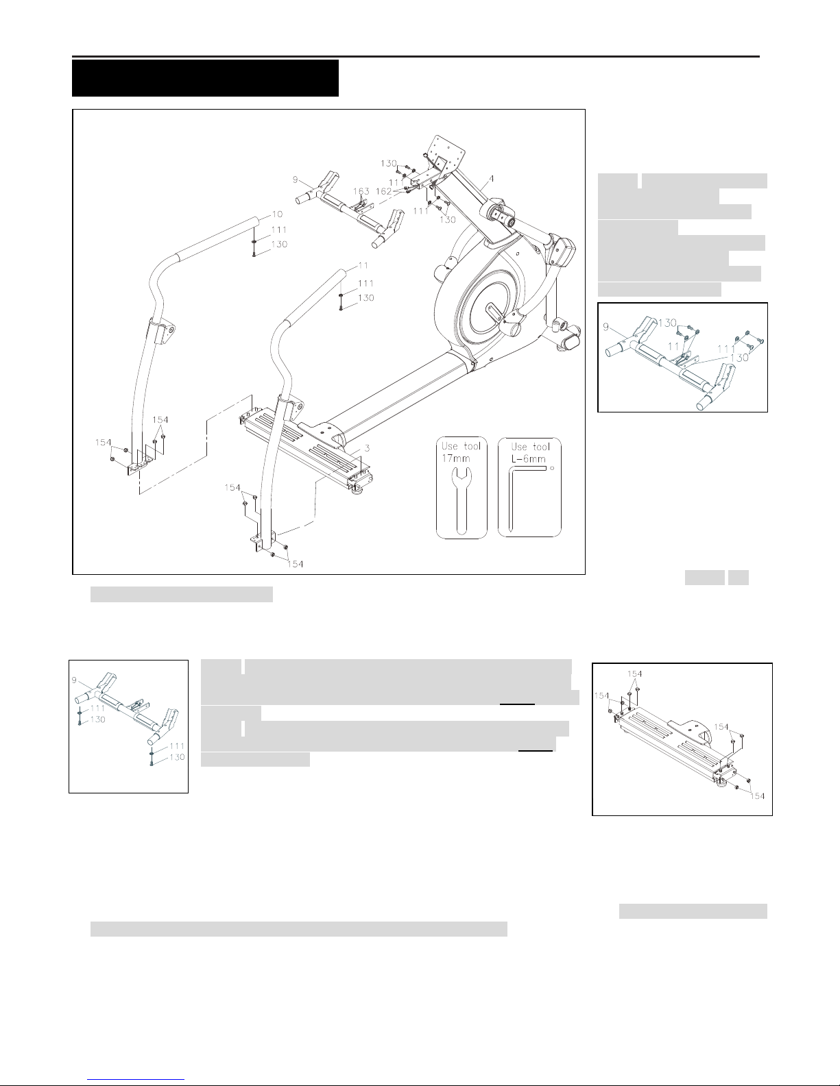
“ASSEMBLY INSTRUCTIONS”
STEP 7 – Wire &
U-Shaped
Handlebar Stand
Assembly
NOTE: For shipping purpose,
4pcs Lock Washers
(M8)(111) and 4pcs Bolts,
Button Head
(M8×p1.25×16mm)(130) are
attached to U-Shaped
Handlebar Stand (9) as the
following draft shown.
a. Remove 4pcs Lock
Washers (M8)(111) and
4pcs Bolts, Button Head
(M8×p1.25×16mm)(130)
from the U-Shaped
Handlebar Stand (9).
b. Connect the Middle Pulse
Sensor Wire (162) to the
Lower Pulse Sensor
Wire (163). NOTE: Be
careful not to pinch the wires.
c. Attach U-Shaped Handlebar Stand (9) to the Upright Post (4) and secure with 4pcs Lock Washers (M8)(111) and
4pcs Bolts, Button Head (M8×p1.25×16mm)(130).
STEP 8 – Long Stationary Handrail Assembly
NOTE: For shipping purpose, 2pcs Lock Washer (M8)(111) and
2pcs Bolts, Button Head (M8xp1.25x16mm)(130) are attached
to bottom of the U-Shaped Handlebar Stand (9) as FIG. 1 shown
on the left.
NOTE: For shipping purpose8pcs Nylon Nuts (M10×p1.5)(154)
are attached to both sides of the Rear Stabilizer (3) as FIG. 2
shown on the right.
Please place all the above pre-attached bolts and washers in a
cleared area and position them on the floor in front of you, these
bolts and washers are for Step 8.
a. Remove 2pcs Lock Washer (M8)(111) and 2pcs Bolt (M8xp1.25x16mm)(130) from the bottom of the U-Shaped
Handlebar Stand (9).
b. Remove 8pcs Nylon Nuts (M10xp1.5)(154) from both sides of the Rear Stabilizer (3).
c. Attach the upper side of Left and Right Long Stationary Handrail (10,11) to the U-Shaped Handlebar Stand (9) and
slightly secure with 2pcs Lock Washers (M8)(111) and 2pcs Bolts (M8xp1.25x16mm)(130). NOTE: Please do not fully
tighten Washers (111) and Bolts (130) for next step c. smooth assembly,
d. Then attach the bottom side of Left and Right Long Stationary Handrail (10,11) to the Rear Stabilizer (3) and secure
with 4pcs Nylon Nuts (M10xp1.5)(154). And then go back to above step b. to fully tighten 2pcs Lock Washers
(M8)(111) and 2pcs Bolts (M8xp1.25x16mm)(130) on the upper side of the Stationary Handrail (10,11).
FIG.1
FIG.2
11
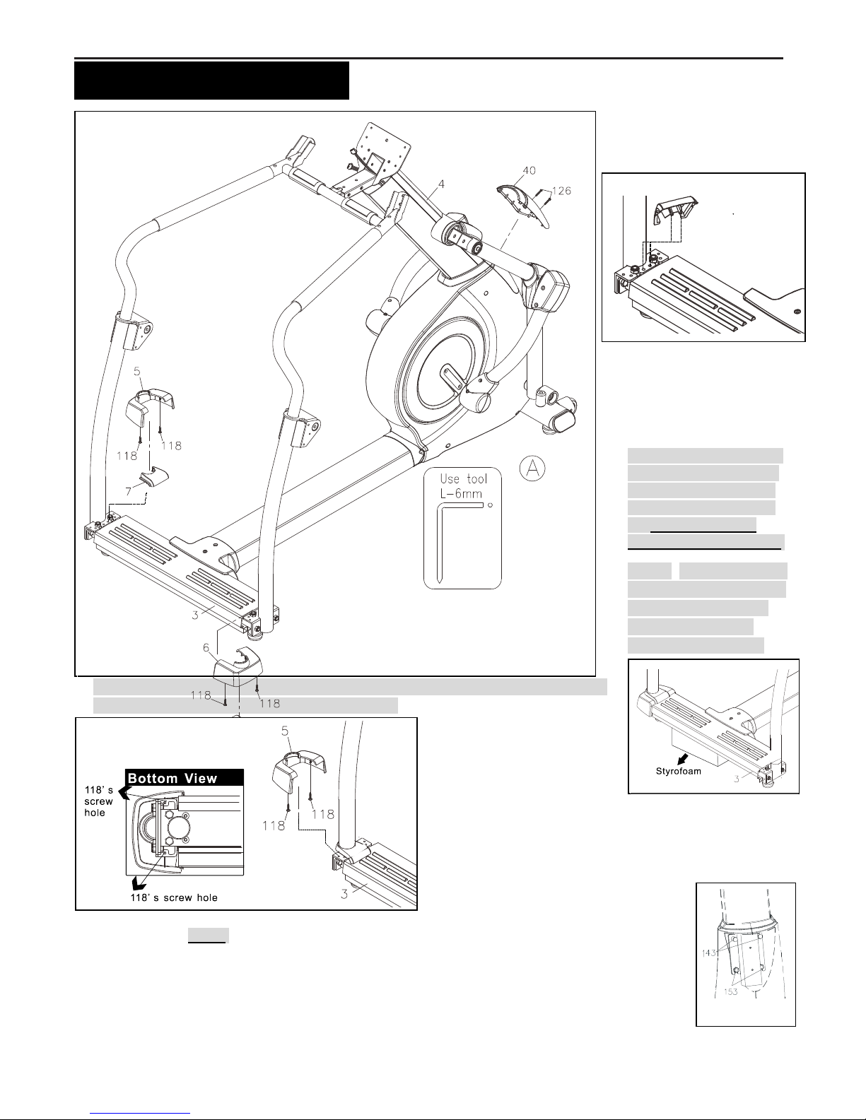
“ASSEMBLY INSTRUCTIONS”
STEP 9 – Bottom
Handrail Decoration
Cover Assembly
a. Follow the above drawing
to first attach the Left
Bottom Handrail
Decoration Cover - Inner
(7) onto the inner side of
the Rear Stabilizer (3).
NOTE: Please make sure
Inner Decoration Cover
(7)’s two ribs insert into
the two holes located on
the inner side of the
upper Rear Stabilizer (3).
b. NOTE: It will be easier to
secure the Screws (118)
under two sides of the
Rear Stabilizer (3),
please first place one
Styrofoam (or any stationary object) under the Rear Stabilizer (3) for the next step
smooth assembly as the draft shown on the right.
c. Refer to the left side
drawing to attach the
Bottom Handrail
Decoration Cover – Left (5)
on the Left Bottom
Handrail Decoration Cover - Inner (7) and secure with
2pcs Screws, Round Head (M4x12mm)(118) into the
bottom of the Rear Stabilizer (3). Repeat the above same
procedure for the right side.
STEP 10 – Front Decoration
Upright Cover Assembly
a. Please refer to FIG. 3 to go back to the front of the Main Frame (1) to fully tighten with 2pcs Bolts,
Hex Head (M10xp1.5x50mm)(143) and 2pcs Nylon Nut (M10xp1.5)(153) with the T-Handle
SOCKET WRENCH (17mm).
b. Attach the Front Decoration Upright Cover (40) onto the front of the Main Frame (1) with 2pcs
Bolts, Round Head (M5xp0.8x30mm)(126).
FIG. 3
 Loading...