

Page 1
Safety Technology International, Inc.
2306 Airport Road • Waterford, Michigan 48327-1209
P
hone: 248-673-9898 • Fax: 248-673-1246
T
oll Free: 800-888-4784 • E-mail: info@sti-usa.com
Web: www.sti-usa.com
S
afety Technology International (Europe) Ltd.
Unit 49G Pipers Road • Park Farm Industrial Estate • Redditch
Worcestershire • B98 0HU • England • Tel: 44 (0) 1527 520 999
F
ax: 44 (0) 1527 501 999 • Freephone: 0800 085 1678 (UK only)
E
-mail: info@sti-europe.com • Web: www.sti-europe.com
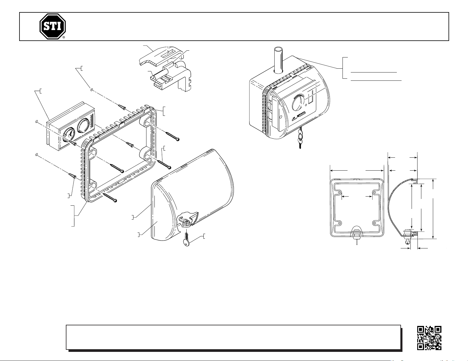
SURFACE MOUNT INSTALLATIONS
FOR ADDTIONAL CLEARANCE A SUB
SPACER KIT MUST BE ORDERED.
S
UB-901 2 in. (50mm) DEPTH
S
UB-905 1.25 in. (32mm) DEPTH
VIEW A
91051 COVER
9105 FRAME
E
XISTING FLUSH
MOUNT THERMOSTAT
KEY (2) PROVIDED
PAR T O F CO VER AS SEMB LY
19033 ANCHOR
(4) PROVIDED
9105 FRAME
CENTER FRAME OVER
EXISTING THERMOSTAT
MARK AND DRILL (4) 1/4 in.
(6.3mm) HOLES AND COMPLETE
ASSEMBLY AS SHOWN.
91051 COVER AND
LOCK ASSEMBLY
19013 SCREW
(4) PROVIDED
FRAME TABS
THE THREE (3) COVER
TABS MUST FACE UPWA RD.
D
RILL (4) HOLES .25 in.
(6.3mm) DIAMETER
F
S
EE
VIEW A
ABOVE
A
STI-9 105 (CLEAR)
STI-9 105-S (SMOKE)
1 in.
(25mm)
4.75 in.
(121mm)
4.95 in.
(126mm)
6.5 in.
(165mm)
8.15 in.
(207mm)
5.5 in.
(140mm)
3.15 in.
(80mm)
3.0 in.
(76mm)
INSTALLATION INSTRUCTIONS
1. Do not remove thermostat. Prior to drilling anchor holes, cover thermostat with a
damp cloth to prevent dust from penetrating the sensor.
2. Center frame over existing thermostat. Mark and drill (4) anchor holes using a 1/4
in. (6.3mm) drill bit. Insert the (4) anchors and complete installation as shown.
NOTE: The (3) tabs on the frame must face upward (View A).
3. Insert the (3) slots on the cover over tabs on the top surface of frame. Rotate cover
downward onto the frame and turn key to lock.
INSTALLATION OF STI-9105 & STI-9105-S THERMOSTAT COVER
All specifications and information shown were current as of publication, and are subject to change without notice.
CLEANING INSTRUCTIONS
To clean cover, remove from wall. Rinse with water to remove abrasive dust and
dirt. Wash with soap or mild detergent using a soft cloth (DO NOT SCRUB). Rinse
once more, then dry with a soft cloth or chamois. To remove grease or wet paint,
rub gently with a cloth wetted thoroughly with naphtha. Then wash and rinse.
DO NOT USE RAZOR BLADES.
Electronic warranty form at www.sti-usa.com/wc14
9105 NOV2005
Page 2

INSTALLATION:
1. DO NOT REMOVE THERMOSTAT. PRIOR TO DRILLING ANCHOR HOLES COVER THERMOSTAT WITH A
CLOTH WETTED WITH WATER TO PREVENT DUST FROM PENETRATING THE SENSOR.
2. CENTER PART No. 9105 FRAME OVER EXISTING THERMOSTAT. MARK AND DRILL (4) ANCHOR
HOLES USING A 1⁄4 in. [6.3mm] DRILL BIT. INSERT THE (4) PART No. 19033 ANCHORS AND
COMPLETE INSTALLATION AS SHOWN.
NOTE: THE (3) TABS ON THE FRAME MUST FACE UPWARD AS SHOWN IN ILLUSTATION ON PAGE 1.
3. INSERT THE (3) TABS ON TOP SURFACE OF FRAME INTO THE (3) SLOTS ON THE COVER, ROTATE
COVER DOWNWARD AND TURN KEY TO LOCK.
CLEANING INSTRUCTIONS
TO CLEAN COVER, REMOVE FROM WALL, RINSE WITH WATER TO REMOVE ABRASIVE DUST AND DIRT.
WASH WITH SOAP OR MILD DETERGENT, USING A SOFT CLOTH (DO NOT SCRUB)
RINSE ONCE MORE, THEN DRY WITH A SOFT CLOTH OR CHAMOIS.
TO REMOVE GREASE OR WET PAINT, RUB GENTLY WITH A CLOTH WETTED THOROUGHLY WITH
NAPHTHA, THEN WASH AND RINSE ONCE MORE. (DO NOT USE RAZOR BLADES)
 Loading...