

Page 1
Protective Cabinet
STI-7554, STI-7555 and STI-7555AED
Features
· Clear, protective polycarbonate cover with siren/strobe alarm.
· Design allows visibility at any angle.
· Complete with mounting hardware and gasket.
· Includes wire shelf, backing plate and siren/strobe alarm — AED models
· External mounting tabs or internal drill dimples.
· Cover includes a coated steel internal mounting plate with a baked on white
enamel finish.
· Siren/strobe alarm lens is red. Also available with amber, green, blue or white
lens.
· Siren offers 32 user selectable tones.
· Alarm can be set for a piercing 100 dB or 85 dB.
· Independent strobe and siren timing of 15 seconds, 30 seconds, 60 seconds or
continuous.
· Powered by a 9 VDC battery or external 12-30 volts.
· Low battery indicator.
We protect the things that protect you.
Page 2

CONTENTS
Warnings ..................................................................................................page 2
Cleaning Instructions ..............................................................................page 2
Dimensions ..............................................................................................page 3
Specifications ..........................................................................................page 3
Installation of Cabinet ............................................................................page 4
Installation of Alarm ................................................................................page 4
Alarm Electronic Setup ............................................................................page 5
Alarm Tones ............................................................................................page 5
Alarm Timing and Volume ......................................................................page 5
Alarm Terminal Strip Connections ..........................................................page 6
Alarm Electronics Assembly ....................................................................page 6
Assembly Parts List ................................................................................page 7
Operation ................................................................................................page 7
Warranty ..................................................................................................page 8
Accessories & Replacement Parts............................................................page 8
WARNINGS
All units are recommended for indoor use. Unit must be tested periodically to
verify the life of battery. STI recommends you change the 9 Volt battery twice
a year. When purchasing a siren/strobe alarm, you will need to periodically
test the connections to make sure audibles function at a sound level to alert
staff. Installer may need to purchase a simple audio-meter, typically available
at your local electronics store, to measure the sound in areas where the alarm
is expected to be heard during normal noise environment. Results from this
test may prove it beneficial to purchase additional siren/strobe alarm units.
All specifications and information shown are current as of publication and
subject to change without notice.
CLEANING
1. Rinse cover with water to remove abrasive dust and dirt.
2. Wash with soap or mild detergent using a soft cloth. (DO NOT SCRUB.)
3. Rinse once more, then dry with a soft cloth or chamois.
4. To remove grease or wet paint, rub gently with a cloth wetted thoroughly
with naphtha, then wash and rinse. (DO NOT USE RAZOR BLADES.)
- 2-
Page 3
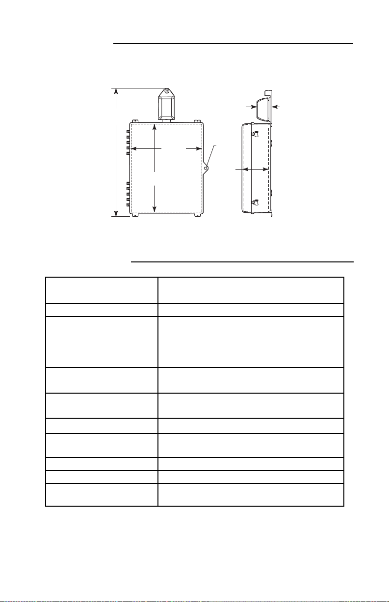
DIMENSIONS
FRONT
R.H. SIDE
4
.31 in.
(
109mm)
33.75 in.
(857mm)
19.75 in.
(502mm)
24.75 in.
(629mm)
7.31 in.
(186mm)
3/8”
DIAMETER
3
SPECIFICATIONS
OPERATING VOLTAGE Internal power 9 VDC battery (not included)
OPERATING TEMPERATURE 32°F -120°
POWER CONSUMPTION Stand by: 50µA
Remote power 12-30 VDC
Siren low volume: 85mA
Siren high volume: 90mA
Strobe: 25mA
SIREN VOLUME Low: 85 dB
High: 100 dB
ALARM TIMING Independent control for siren and strobe:
15s, 30s, 60s, continuous
LOW BATTERY WARNING LED flash once every 30 seconds
FORM C DRY CONTACTS 0-30VAC/DC, 1 Amp
RATED FOR Contacts reset after longest alarm setting
KEY SWITCH Alarm on: normally closed
ALARM SWITCH Stand by: normally open contact required
POLYCARBONATE UL94V-2
FLAMMABILITY RATING
- 3-
Page 4

DRILL
3-/16 DIA HOLES
19018 ANCHOR
#8-10
(2) PROVIDED
19039 SCREW
#6 x 1 1/4 in.
(2) PROVIDED
BASE PLATE
18074 SWITCH LOCK
SUB-SA505 KEY SWITCH
MOUNTING BRACKET
3 9/32 in.
18075 REPLACEMENT
#801 KEY
ENCLOSURE
ROUTE THE TWO KEY
SWITCH WIRES THROUGH
THE HOLE AS SHOWN
WIRE ACCESS HOLE
ROUTE THE TWO REED
SWITCH WIRES FROM
CABINET THROUGH THE
HOLE AS SHOWN
04876
MOUNTING
PLATE
OPTIONAL
TAB
M
OUNTING
LOCATION
19033 ANCHOR
(6) PROVIDED
1
9002 SCREW
#8-32 x 3/8 in.
(4) PROVIDED
6297550
GASKET
19013 SCREW
#
10 x 1 1/2 in.
(6) PROVIDED
06298 MOUNTING TABS
(6) PROVIDED
07550WR WIRE
SHELF ON AED
MODELS (ADJUSTABLE)
R
OTARY ACTION
LATCH (2) PROVIDED
SHOWN WITH
COVER CLOSED
0
7551WR WIRE RACK
(INCLUDED WITH
AED MODEL)
19002 #8-32 x 3/8 in.
SCREWS AND (4) 19055
#8-32 KEPS NUTS PROVIDED
INSTALLATION OF CABINET
Note: Installation of cabinet should be before installation of alarm
because the mounting bracket butts up to cabinet.
1. Insert the (4 or 6) mounting tabs fully
into backbox mounting tab slots. Use
rubber mallet if necessary.
2. After selecting a suitable location,
place cabinet in closed position,
against the wall. Mark and
drill (4 or 6) 1/4 in.
diameter holes. Insert the
(4 or 6) 19033 anchors.
Mount cabinet by
driving in the four or six
#10 x 1 1/2 in. screws.
3. For AED model install shelf, close
and lock cabinet.
INSTALLATION OF ALARM
STEP 1 - MOUNTING OPTIONS
TO KEY MOUNT PLATE OR INTO WALL WITHOUT ELECTRICAL BOX
- 4-
Page 5

1
ALARM TIMING
VOLUME
STROBE TIMING
ON
OFF
1
2
3
4
5
0
S1
ALARM TONE
S2
A
LARM TIMING
STROBE TIMING
VOLUME
L
ED QTY 10
LOW BATTERY
I
NDICATOR LED
T
ERMINAL STRIP
TAMPER SWITCH
(
REAR VIEW)
W
IRE ENTRY
B
ATTE RY
BATTERY CABLE
S
IREN
O
STEP 2 - ELECTRONIC SETUP -
O
O
SELECT ALARM TONE AND TIMING SEQUENCE
NOTE: Select-Alert must be on a flat surface and lens must be
installed or the tamper switch will trigger the alarm.
STEP 3 - ALARM TONES - S1
1 2 3 4 5
1 0 0 0 0 0 BUZZ
*
2 1 0 0 0 0 SLOW ON/OFF
3 0 1 0 0 0 SLOW SIREN
4 1 1 0 0 0 3 BEEP/PAUSE/REPEAT
5 0 0 1 0 0 UFO FAST
6 1 0 1 0 0 FAST SIREN
7 0 1 1 0 0 #5 FAST
8 1 1 1 0 0 #2 MEDIUM
9 0 0 0 1 0 #5 MEDIUM
10 1 0 0 1 0 SWOOP MEDIUM
11 0 1 0 1 0 #3 MEDIUM
12 1 1 0 1 0 BUZZ TONE
13 0 0 1 1 0 STEADY FAST
14 1 0 1 1 0 SWOOP SLOW
15 0 1 1 1 0 CONTINUOUS
16 1 1 1 1 0 FAST REPEAT
WIRES TO SIREN
1 2 3 4 5
17 0 0 0 01 STANDARD ALARM
18 1 0 0 0 1 #3 FAST
19 0 1 0 0 1 #5 SLOW
20 1 1 0 0 1 FAST BEEP
21 0 0 1 0 1 SOUND A
22 1 0 1 0 1 SOUND B
23 0 1 1 0 1 SOUND C
24 1 1 1 0 1 SOUND D
25 0 0 0 1 1 SOUND D LOUD
26 1 0 0 1 1 SOUND E
27 0 1 0 1 1 SOUND F
28 1 1 0 1 1 SOUND G
29 0 0 1 1 1 SOUND H
30 1 0 1 1 1 #4 LOW
31 0 1 1 1 1 SOUND K
32 1 1 1 1 1 CONTINUOUS FAST
NOTE Sound may be disabled by clipping wires to
the siren. THIS WILL VOID ALL WARRANTIES.
Remove two screws on circuit board; leave
enough length of wire to possibly reattach in
the future. Then insulate wires to prevent
shorting to electronic components.
STEP 4 - ALARM TIMING AND VOLUME - S2
ALARM
TIMING
15 seconds 1111 High
*
30 seconds 1010 1
60 seconds 0101 Low
Continuous 00 00 0
1 = ON 0 = OFF
*Factory default settings
- 5-
1 2
STROBESIREN
3 4 5
VOLUME
Page 6
05050- LENS COLORS
A - AMBER
B - BLUE
G - GREEN
R - RED
W - WHITE
19002 SCREW
#8-32 x 3/8 in.
(4) PROVIDED
ELECTRONICS
INSTALL ED
BASE PLATE
WIRE ACCESS HOLE
19016 TAMPER-PROOF
TOOL (1) PROVIDED
19011 TAMPER-PROOF
SCREW
ROUTE WIRES
THRU HOLE
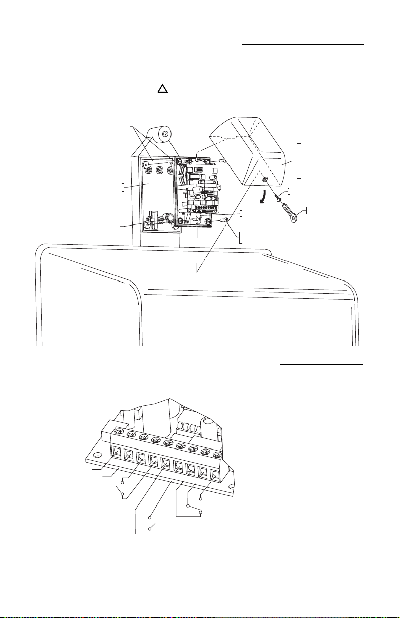
STEP 5 - ELECTRONICS ASSEMBLY
REMOTE POWER IN
12-24 VDC, 125mA
(OPTIONAL)
+
-
OFF ON
MAIN POWER
CONTROL TO
KEY SWITCH
STAND
BY
REED
SWITCH FROM CABINET
FORM "C"
DRY CONTACTS
NORMALLY OPEN
COM
+
-
D
C
I
N
K
E
Y
S
W
I
T
C
H
A
L
A
R
M
S
WI
T
C
H
N
C
C
O
M
N
O
NORMALLY CLOSED
ACTIVE
iring: After mounting circuit board assembly, connect wires. Refer to terminal strip connections (step 6).
W
Lens installation: Slide lip of lens behind circuit board mounting plate. Rotate lens into position. Secure with
tamperproof screw and special wrench. Unit will not operate properly if lens cover is not installed.
!
STEP 6 - TERMINAL STRIP CONNECTIONS
- 6-
NOTE “DC IN” are the only
polarity sensitive terminals.
When external power is
used, battery will act as a
backup. “Dry Contacts: NC,
COM, NO” are used for
remote alarm monitoring.
Page 7

ASSEMBLY PARTS LIST
SIREN/STROBE ALARM
QTY. PART # DESCRIPTION
1 05000 Electronics assembly (includes base plate & electronics assembly)
1 05050-R Red lens (unless otherwise specified)
1 09723 Key switch mounting bracket
2 18075 #801 key
1 18074 Switch lock
1 18151 N.C. reed switch and magnet (installed in cabinet)
4 19002 Screw #8-32 x 3/8 in.
2 19039 Screw #6 x 1 1/4 in.
2 19018 Anchor #8-10
1 19011 #8-32 x 1/2 in. tamper screw
1 19016 Tamper wrench
1 BAT-9VDC 9 volt battery
CABINET
1 07550 Hinged polycarbonate enclosure
6 06298 Mounting tabs
6 19013 #10 x 1 1/2 in. screw
6 19033 Plastic anchor
1 07550WR Wire shelf (Included with AED models only)
1 07551WR Wire rack (Included with AED models only)
1 04876 Mounting plate
4 19002 #8-32 x 3/8 in. screw
1 6297550 Gasket
1 07503 Thumb lock - STI-7555 models
1 18050 Key lock
2 18054 CH751
STI-7554 models
}
STEP 7 - OPERATION
• Turn key switch on to arm.
• Cycle key switch to reset alarm.
• Alarm will sound when cabinet is opened (alarm switch is electronically
closed), alarm cover is removed or unit is removed from the wall.
• To service, turn key switch off.
- 7-
Page 8

WARRANTY INFORMATION
Three year guarantee against breakage of polycarbonate housing (one year
on electro mechanical and electronic components).
Electronic warranty form at www.sti-usa.com/wc14.
ACCESSORIES AND REPLACEMENT PARTS
AED-LBL Optional AED label - 2 included (applied to
sides of cabinet; must be factory installed)
STI-SA5000-R Replacement Siren/Strobe Alarm
18054 Replacement key for cabinet lock on STI-7554
18075 Replacement key for Siren/Strobe Alarm
07550WR Wire shelf (included with AED models)
07551WR Wire rack (included with AED models)
2306 Airport Road
Waterford, Michigan 48327-1209
Phone: 248-673-9898 • Toll Free: 800-888-4784 • Fax: 248-673-1246
www.sti-usa.com
Safety Technology International (Europe) Ltd.
Unit 49G Pipers Road • Park Farm Industrial Estate • Redditch
Worcestershire • B98 0HU • England • Tel: 44 (0) 1527 520 999
Fax: 44 (0) 1527 501 999 • Freephone: 0800 085 1678 (UK only)
E-mail: info@sti-europe.com • Web: www.sti-europe.com
Printed in USA Inst. Sht. STI-7554/STI-7555AED, DEC2010
 Loading...