

Page 1
19033 ANCHOR
(4) PROVIDED
E
M
E
RG
E
N
C
Y
U
S
E
O
N
L
Y
STI-7532 - KEY LOCK
STI-7533 & STI-7533AED - THUMB LOCK
S
T
O
P
07530WR
ADJUSTABLE WIRE SHELF
INCLUDED WITH STI-7533AED
0
MOUNTING
TAB SLOTS
04875 MOUNTING PLATE
19002 SCREW
#8-32 x 3/8 in.
(4) PROVIDED
OPTIONAL SHELF
MOUNTING POSITION
06298
MOUNTING TABS
(4) PROVIDED
19013 SCREW
#10 x 1 1/2 in.
(4) PROVIDED
07530 CABINET
ASSEMBLY
6297530
GASKET
A
9 VOLT ALKALINE BATTERY
06201 STOP ALARM COVER
19016 TAMPERPROOF TOOL
(1) PROVIDED
19032 KEY (2) PROVIDED
19011 SCREW - TAMPERPROOF
(2) PROVIDED
19039 SCREW
#6 x 1 1/4 in.
(2) PROVIDED
19018 ANCHOR
(2) PROVIDED
MAGNETIC CONTACT
REED SWITCH
ALARM MOUNTING PLATE
06202 BACKPLATE
S
T
O
P
E
M
E
R
G
E
N
CY
U
S
E
O
N
L
Y
EMERGENCY USE ONLY
FRONT
5.375 in.
(137mm)
R.H. SIDE
STOP
23 in.
(584mm)
12.2 in.
(310mm)
14.2 in.
(360mm)
2.25 in.
(57mm)
6.44 in.
(164mm)
1/4” DIA.
v
moun
orien
as sho
t
(4) 1/4 in. diame
and c
(Do no
ALARM MOUNTING PLATE
CABINET
WIRE ACCESS HOLE
ROUTE THE 2 SWITCH WIRES
THROUGH THE HOLE AS SHOWN
OPTIONAL MOUNTING
HOLES (4)
v
moun
orien
as sho
t
(4) 1/4 in. diame
and c
W
(Do no
VIEW A
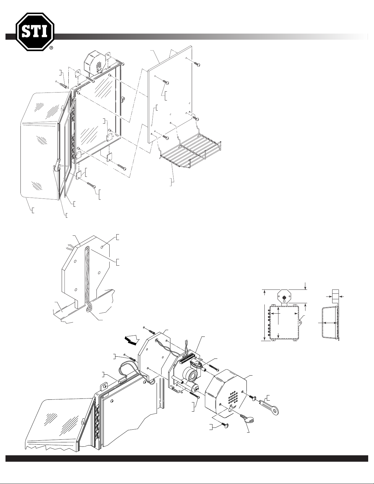
INSTALLATION OF STI-7532, STI-7533 & STI-7533AED PROTECTIVE CABINET
INSTALLATION OF CABINET
1. Insert the (4) 06298 mounting tabs fully into
back box mounting tab slots. Use rubber mallet
f necessary.
i
2. After selecting a suitable location, place
cabinet in closed position, against the wall.
Mark and drill (4) 1/4 in. diameter holes.
Insert the (4) 19033 anchors.
3. Select one of the two shelf mounting locations,
install shelf. Close and lock cabinet.
4. Place cabinet in position making sure the (2)
switch wires are not pinched between the wall
and cabinet. Drive in the (4) screws. Cabinet is
now secure.
INSTALLATION OF ALARM ASSEMBLY
1. Place the alarm mounting plate on the top
center of cabinet. Select at least two of the
four optional mounting holes. Mark and drill
3/16 in. holes and install the 19018 anchors.
2. Fish the magnetic switch wires through the
alarm mounting plate and the siren backplate
(View A). Next, drive the two alarm mounting
screws into the previous installed anchors.
3. Install the two magnetic switch wires following
the terminal switch diagram (View B).
4. Install the alarm cover using the (2)
tamperproof screws and provided tool.
Safety Technology International, Inc. • 2306 Airport Rd. • Waterford, Michigan 48327-1209 • 800-888-4784 • Fax: 248-673-1246 • Web: www.sti-usa.com • Email: info@sti-usa.com
Page 2
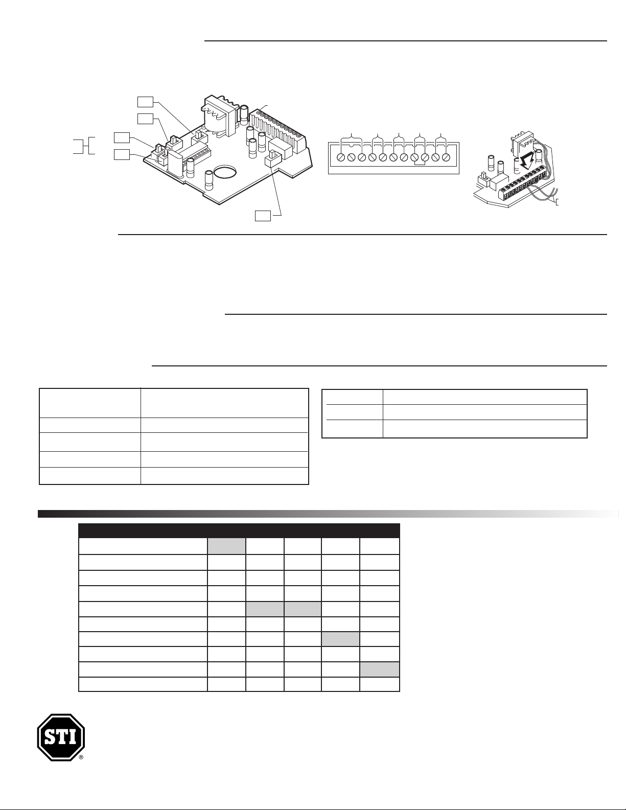
CIRCUIT BOARD SET-UP
J
P5
J
P2
JP4
JP3
JP7
ALARM VOLUME SWITCH
TRIP DELAY SWITCH
ARMING SWITCH
(FACTORY DEFAULT SETTINGS)
(ON)
(ON)
(OFF)
(OFF)
(OFF)
ALARM CIRCUIT BOARD SET-UP
A
LARM
DURATION
S
WITCH
T
ERMINAL BLOCK
(
B
FROM MAGNETIC
CONTACT SWITCH
N
C
COM
N
O
GD
V
+
RS1
RS2
KEYSW
VIEW B
TERMINAL BLOCK WIRING CONNECTIONS
FORM C
DRY
CONTACTS
REMOTE
POWER
INPUT
9-24 VDC
KEY SWITCH
TERMINALS
MAGNETIC CONTACTTIC
REED SWITCH
JUMPER
VIEW B
WARNINGS
All units are recommended for indoor use. Unit must be tested periodically to verify the life of battery. STI recommends you change the battery twice a year. Duracell
MN 1604 or equivalent recommended. Installer may need to purchase a simple audio-meter, typically available at your local electronics store, to measure the sound
in areas where the alarm is expected to be heard during normal noise environment. Results from this test may prove it beneficial to purchase an additional alarm.
When purchasing a remote unit (STI-6403) you will need to periodically test the connections to make sure audibles function at a sound level to alert staff. Maximum of
three STI-6403 may be used in parallel. All specifications and information shown are current as of publication and subject to change without notice.
WARRANTY INFORMATION
· Three year guarantee against breakage of polycarbonate in normal use (one year on electro mechanical and electronic components).
· Electronic warranty form at www.sti-usa.com/wc14.
SPECIFICATIONS
Alarm Electronics
Power Source
Horn Volume at 1 ft. 95 dB low / 105 dB high
Relay Output Form C Dry Contacts 0-30 VDC or VAC, 1 Amp
Stand by Current 10uA
Alarm Current 130mA at 95 dB / 200mA at 105 dB
SWITCH SETTINGS
9 VDC Alkaline or 9V-24VDC wired
Class II UL Listed transformer
Polycarbonate Alarm Cover:
Dimensions 5.375” W x 5.375” H x 2 “ D (137mm x 137mm x 51mm)
Flammability: UL94 V-2
Wall Thickness: 0.12 in (3.05mm)
FEATURE JP2 JP3 JP4 JP5 JP7
Volume - High (105 dB) at 1 ft. ON*
Volume - Low (95 dB) at 1 ft. OFF
Duration - 30 Second Alarm OFF OFF
Duration - 180 Second Alarm OFF ON
Duration - Continuous Alarm ON* OFF*
Duration - Annunciator Mode ON ON
Trip - Immediate OFF*
Trip - 15 Second Delay ON
Arming - Immediate ON*
Arming - 15 Second Delay OFF
Safety Technology International, Inc.
2306 Airport Road • Waterford, Michigan 48327-1209
Phone: 248-673-9898 • Toll Free: 800-888-4784
Fax: 248-673-1246 •
Printed in USA
www.sti-usa.com
*Factory Settings
Safety Technology International (Europe) Ltd.
Unit 49G Pipers Road • Park Farm Industrial Estate • Redditch
Worcestershire • B98 0HU • England • Tel: 44 (0) 1527 520 999
Fax: 44 (0) 1527 501 999 • Freephone: 0800 085 1678 (UK only)
E-mail: info@sti-europe.com • Web: www.sti-europe.com
Note: Slide black lever to desired ON/OFF
position as labeled on circuit board.
Inst. Sht. 7532, 7533, &7533AED, JAN2014
 Loading...