

Page 1
MAGNET
6297520 GASKET
(
1) PROVIDED
04874
MOUNTING
PLATE
SCREW #8-32 x 1/2 in.
(4) PROVIDED
AMS-10S MAGNETIC CONTACT
S
WITCH WITH 24 in. WIRE LEADS
19013 SCREW
#10 x 1 1/2 in.
(4) PROVIDED
06298 MOUNTING TABS
(4) PROVIDED
19033 ANCHOR
(
4) PROVIDED
STI-7523 THUMB LOCK
STI-7522 KEY LOCK AVAILABLE
S
T
O
P
S
T
O
P
E
M
E
R
G
E
N
C
Y
U
S
E
O
N
L
Y
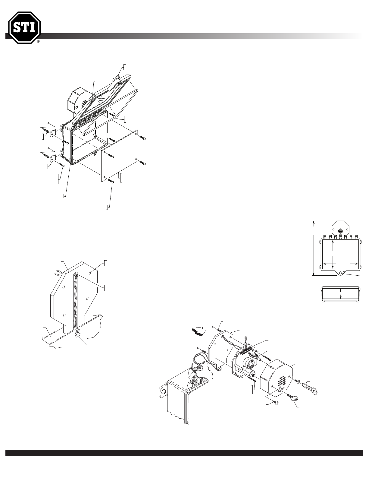
INSTALLATION OF STI-7522 & STI-7523 PROTECTIVE CABINET
ALARM MOUNTING PLATE
CABINET
WIRE ACCESS HOLE
ROUTE THE 2 SWITCH WIRES
THROUGH THE HOLE AS SHOWN
VIEW A
OPTIONAL MOUNTING
HOLES (4)
A
9 VOLT ALKALINE BATTERY
ALARM COVER
19016 TAMP ERPRO OF TOOL
19032 KEY (2) PROVIDED
19011 SCREW - TAMP ERPRO OF
(2) PROVIDED
19039 SCREW
#6 x 1 1/4 in.
(2) PROVIDED
ALARM MOUNTING PLATE
06202 BACKPLATE
ST
OP
EMER
GENC
Y
US
E
ONL
Y
STOP
19018 ANCHOR (2) PROVIDED
T
3.125 in.(79mm)
10.875 in.
(276mm)
8.875 in.(225mm)
STOP
EMERGENCY USE ONLY
FRONT VIEW
TOP VIEW
1
6.00 in.
(406mm)
*
INSTALLATION OF STI-7523 ENCLOSURE
1. Insert the (4) mounting tabs fully into backbox mounting tab
slots. Use rubber mallet if necessary.
2. After selecting a suitable location, place enclosure in closed
position, against the wall. Mark and drill (4) 1/4 in. diameter
holes. Insert the (4) 19033 anchors. Close and lock enclosure.
3. Place enclosure in position making sure the (2) switch wires
are not pinched between the wall and enclosure. Drive in the
(4) screws. Enclosure is now secure.
INSTALLATION OF ALARM ASSEMBLY
1. Place the alarm mounting plate on the
top center of enclosure. Select at least
two of the four optional mounting
holes. Mark and drill 3/16 in. holes and
install the 19018 anchors.
2. Fish the magnetic switch wires through
the alarm mounting plate and the siren
backplate (View A). Next, drive the two
alarm mounting screws into the
previous installed anchors.
3. Install the two magnetic switch wires
following the terminal switch diagram
(View B).
4. Install the alarm cover using the (2)
tamperproof screws and provided tool.
* 1/4” Diameter
Safety Technology International, Inc. • 2306 Airport Rd. • Waterford, Michigan 48327-1209 • 800-888-4784 • Fax: 248-673-1246 • Web: www.sti-usa.com • Email: info@sti-usa.com
Page 2
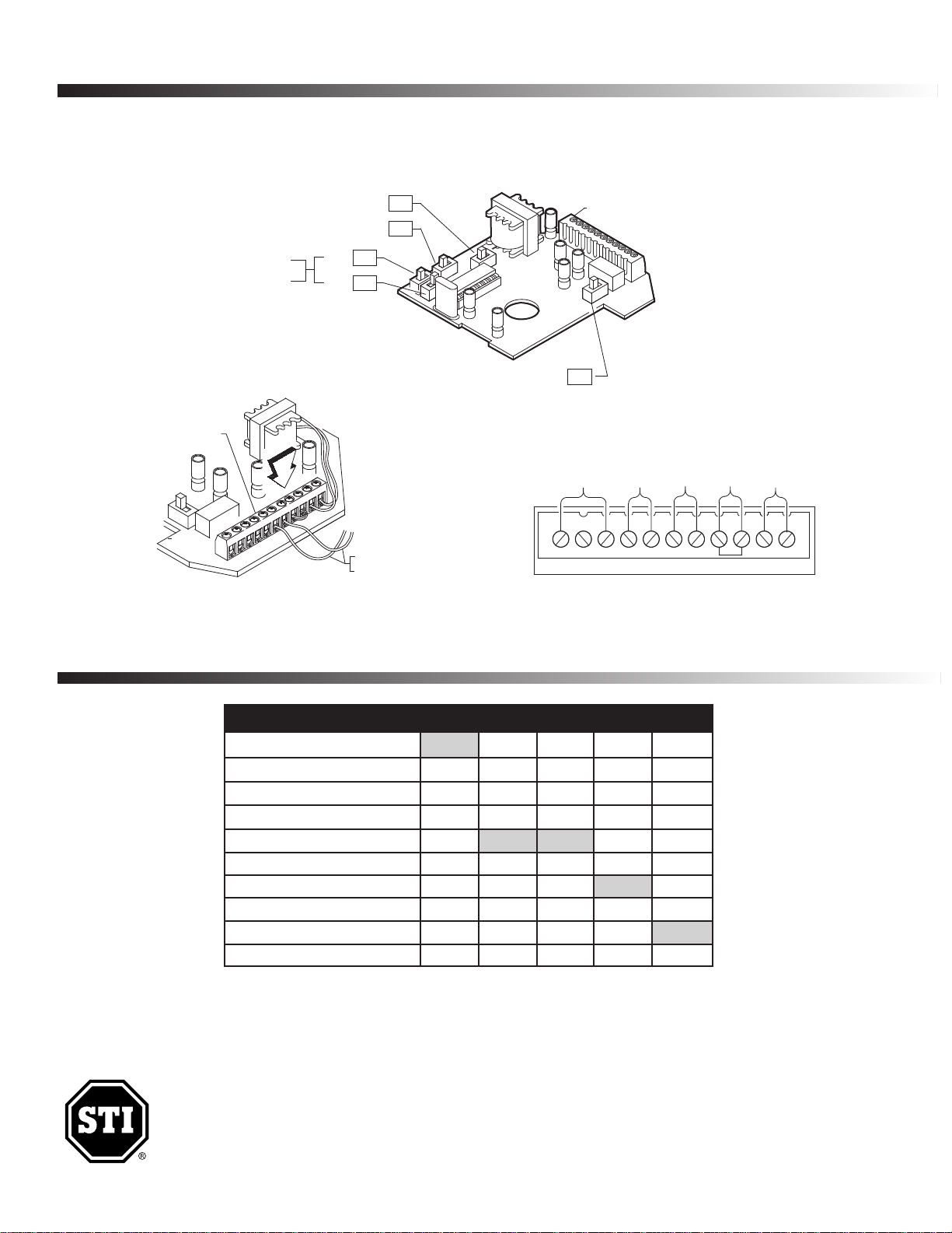
CIRCUIT BOARD SET-UP
J
P5
J
P2
JP4
JP3
JP7
ALARM VOLUME SWITCH
TRIP DELAY SWITCH
A
RMING SWITCH
(FACTORY DEFAULT SETTINGS)
(ON)
(ON)
(OFF)
(OFF)
(OFF)
ALARM CIRCUIT BOARD SET-UP
ALARM
DURATION
S
WITCH
TERMINAL BLOCK
B
FROM MAGNETIC
C
ONTACT SWITCH
T
ERMINAL STRIP
NC
COM
NO
GD
V
+
R
S1
RS2
K
EYSW
VIEW B
FORM C
DRY
CONTACTS
REMOTE
POWER
INPUT
9-24 VDC
KEY SWITCH
TERMINALS
TERMINAL BLOCK WIRING CONNECTIONS
MAGNETIC CONTACT
REED SWITCH
JUMPER
M
SWITCH SETTINGS
Safety Technology International, Inc.
2306 Airport Road • Waterford, Michigan 48327-1209
Phone: 248-673-9898 • Toll Free: 800-888-4784
Fax: 248-673-1246 • www.sti-usa.com
Printed in USA
FEATURE JP2 JP3 JP4 JP5 JP7
Volume - High (105 dB) at 1 ft. ON*
Volume - Low (95 dB) at 1 ft. OFF
Duration - 30 Second Alarm OFF OFF
Duration - 180 Second Alarm OFF ON
Duration - Continuous Alarm ON* OFF*
Duration - Annunciator Mode ON ON
Trip - Immediate OFF*
Trip - 15 Second Delay ON
Arming - Immediate ON*
Arming - 15 Second Delay OFF
*Factory Settings
Note: Slide black lever to desired ON/OFF position as labeled on circuit board.
Electronic warranty form at www.sti-usa.com/wc14
Safety Technology International (Europe) Ltd.
Unit 49G Pipers Road • Park Farm Industrial Estate • Redditch
Worcestershire • B98 0HU • England • Tel: 44 (0) 1527 520 999
Fax: 44 (0) 1527 501 999 • Freephone: 0800 085 1678 (UK only)
E-mail: info@sti-europe.com • Web: www.sti-europe.com
Inst. Sht. 7523, JAN2010
 Loading...