

STI 7520-HTR User Manual
Safety Technology International, Inc.
2
306 Airport Road • Waterford, Michigan 48327-1209
Phone: 248-673-9898 • Fax: 248-673-1246
Toll Free: 800-88 8-4784 • E-mai l: info @sti-us a.com
Web: www.sti-usa.com
Safety Technology International (Europe) Ltd.
U
nit 49G Pipers Road • Park Farm Industrial Estate • Redditch
W
orcestershire • B98 0HU • England • Tel: 44 (0) 1527 520 999
Fax: 44 (0) 1527 501 999 • Freephone: 0800 085 1678 (UK only)
E-mail: info@sti-europe.com • Web: www.sti-europe.com
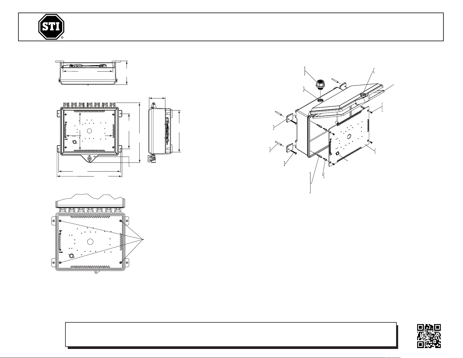
7
.11 in.
(181mm)
12.11 in.
(308mm)
8.46 in.
(214mm)
3.25 in.
(83mm)
12.51 in.
(318mm)
13.17 in.
(335mm)
8
.09 in.(206mm)
10.06 in.(256mm)
1/4” DIAMETER
07503 THUMB LOCK (STI-7521-HTR)
18050 KEY LOCK (STI-7520-HTR)
6
297520 COVER GASKET
19051 #8-32 x 3/8 in.
FLAT HEAD SCREW
(
4) PROVIDED
SUB-7520-HTR
ASSEMBLY
19083 M-F #8-32 x 3/8 in.
STANDOFF (4) PROVIDED
ADDITIONAL STANDOFFS MAY BE REQUIRED
WHEN USING A WATERTIGHT
CONDUIT HUB (NOT INCLUDED)
19083 M-F #8-32 x 3/8 in.
19093 M-F #8-32 x 1-1/2 in.
19056 M-F #8-32 x 3 in.
19013 #10 x 1-1/2 in. PAN
HEAD SCREW (4) PROVIDED
19033 #10-12 PLASTIC
ANCHOR (4) PROVIDED
06298 MOUNTING
TAB (4) PROVIDED
NOTE: HOLE TO BE LOCATED
A
ND CUT IN BY INSTALLER
18021 3/4 in. NPT
WATERTIGHT CONDUIT
H
UB (NOT INCLUDED)
CONTROL THERMOSTAT
1
0.09 in.
(256mm)
4.79 in.
(122mm)
REMOVE
ILLUSTRATION 1
INSTALLATION OF HEATED PROTECTIVE CABINETS STI-7520-HTR, STI-7521-HTR
All specifications and information shown were current as of publication, and are subject to change without notice.
ILLUSTRATION 2
INSTALLATION INSTRUCTIONS
1. Remove heater plate assembly (Illustration 1) from back box by removing 4 flat head
screws and set aside.
2. Mount back box and cover assembly in desired position. With hinges horizontal or
vertical, insert the (4) mounting tabs into the back box slots (see Illustration 2).
Mark and drill (4) 1/4” diameter holes 1 1/4” deep. Insert plastic anchors and screw
back box to wall with (4) #10 x 1 1/2” screws.
3. Route wires for heater and appliance into back box through conduit or small hole
properly sealed.
Electronic warranty form at www.sti-usa.com/wc14
7520-HTR IS JAN 2010
Safety Technology International, Inc.
2
306 Airport Road • Waterford, Michigan 48327-1209
Phone: 248-673-9898 • Fax: 248-673-1246
Toll Free: 800-88 8-4784 • E-mai l: info @sti-us a.com
Web: www.sti-usa.com
Safety Technology International (Europe) Ltd.
U
nit 49G Pipers Road • Park Farm Industrial Estate • Redditch
W
orcestershire • B98 0HU • England • Tel: 44 (0) 1527 520 999
Fax: 44 (0) 1527 501 999 • Freephone: 0800 085 1678 (UK only)
E-mail: info@sti-europe.com • Web: www.sti-europe.com
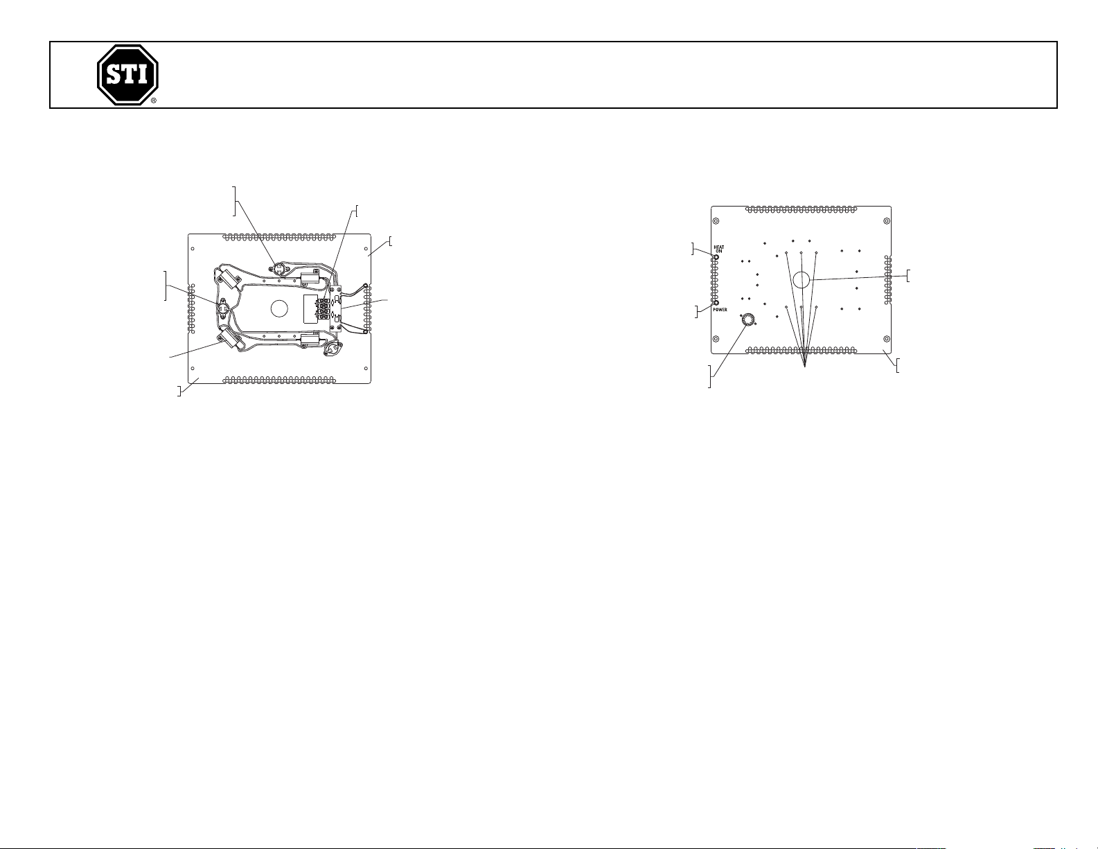
“HEAT ON”
RED LED
“POWER ON”
GREEN LED
CONTROL THERMOSTAT
CLOSED @ 50°F
OPEN @ 70°F
#6-32 THREADED HOLES
FOR MOUNTING ELECTRONIC
DEVICE (6 PLACES)
SUB-7520-HTR
(FRONT VIEW)
D
EVICE WIRING
ACCESS HOLE
O
VER TEMP SAFETY
T
HERMOSTAT
OPEN @ 120°F
CLOSED @ 90°F
LOW TEMP WARNING
THERMOSTAT
C
LOSED @ 32°F
OPEN @ 50°F
RESISTOR HEATER
SUB-7520-HTR
(BACK VIEW)
TERMINAL BLOCK
(4 CONNECTION)
1
/8 in. THICK ALUMINUM
M
OUNTING PLATE
LED CONTROL
ILLUSTRATION 3
ILLUSTRATION 4
JAN2010
4. Connect heater power and control wires.
a. Connect low temperature monitor terminals to supervisory panel
if used (see Illustration 3).
b. Connect power terminals to power source. 12-24 volt AC/DC.
• Heating capacity is determined by input voltage. Be sure
the power source has enough capacity to support the load
at the input voltage.
12 Volt, 19 WATTS
16.5 Volt, 36 WATTS
24 Volt, 77 WATTS
• 16.5 VAC adapter included
5. Mount the heater plate assembly to the back box with
control thermostat toward bottom of enclosure (see
Illustration 2). Be sure to route wires for electronic device
through the hole in the center of the heater plate before
attaching heater plate. For vertical mounting (hinges to
right or left side) be sure control thermostat is towards
the bottom of the enclosure.
6. Connect the electronic device and mount to the heater
plate in mounting holes indicated using #6 - 32 x 1/2”
screws (2) provided.
NOTE: If moisture buildup occurs, drill a weep
hole on bottom side of back box.
7520HTR INSTALL
 Loading...