

Page 1

Safety Technology International, Inc.
2
306 Airport Road • Waterford, Michigan 48327-1209
P
hone: 248-673-9898 • Fax: 248-673-1246
Toll Free: 800-88 8-4784 • E-mai l: info @sti-us a.com
Web: www.sti-usa.com
S
afety Technology International (Europe) Ltd.
Unit 49G Pipers Road • Park Farm Industrial Estate • Redditch
W
orcestershire • B98 0HU • England • Tel: 44 (0) 1527 520 999
F
ax: 44 (0) 1527 501 999 • Freephone: 0800 085 1678 (UK only)
E
-mail: info@sti-europe.com • Web: www.sti-europe.com
3
1
2
1
6
4
12
11
7
5
CABLE
14
6
1
3
8
9
10
15
+ -
Output:
12 VDC
500 mA
Input:
24 VAC
40 Watt
~
A
+ -
O
utput:
1
2 VDC
5
00 mA
I
nput:
2
4 VAC
40 Watt
~
CONNECTIONS:
1. Connect 24 VAC, 40 Watt power supply to input terminals.
2. 12 VDC, 500 mA output can power most cameras.
Refer to camera manufacturer’s specifications.
INSTALLATION INSTRUCTIONS
1. Remove housing lid (1)
a. Open lid
b. Remove tether screw (3) from housing base (4)
c. Slide lid toward rear of housing and lift off
2. Remove mounting bracket arm (5) from bracket plate (6) by removing angle positioning screw (7)
3. Loosen but do not remove, 4 screws (8) holding the camera mounting plate (9). Remove plate. Attach
the camera to the plate using the screw provided (10).
4. Install the camera and mounting plate into the housing, position the camera to the glass, and tighten
the 4 screws.
5. Pull cables through bracket arm and mount the bracket arm to the wall using lag bolts (11) (lag shields
(12) are for use in masonry walls only).
6. Cut a small slit in protective gasket (13) inside the housing base for the wires to enter the housing.
7. Route the wires through the bracket pivot (14) (make sure the hole in the pivot faces toward the wall
to allow clear passage of the wires) and up into the housing
8. Place housing on bracket arm and install angle positioning screw into pivot. Adjust to proper angle
before tightening.
9. Replace cover and tether from step 1.
10. If required foam pads are provided to block sprayed water from entering into the housing through the
front screen (15) and rear screen under fan (16). Caution is advised when blocking fresh air screens
since moisture may build up inside housing.
INSTALLATION OF STI-7150K CCTV HOUSING - DIE CAST HEAVY DUTY
All specifications and information shown were current as of publication, and are subject to change without notice.
SPECIFICATIONS:
Input: 24 VAC, 40 Watts
Output: 12 VDC, 500mA
Power
Fan: 12 VDC, 1.3 W
Heater: 15 W @ 24VAC
High Ambient Temperature:
Fan “ON” @ 95°F ± 6°(35°C ± 3°)
Fan “OFF” @ 72°F ± 5°(22°C ± 4°)
Low Ambient Temperature:
Fan & Heat “ON” @ 50°F ± 6°(10°C ± 4°)
Fan & Heat “OFF” @ 68°F ± 3° (20° ± 3°)
Weight without Camera:
9.2lbs.(4.18kg)
Electronic warranty form at www.sti-usa.com/wc14
DETAIL A
7150K FEB2010
Page 2
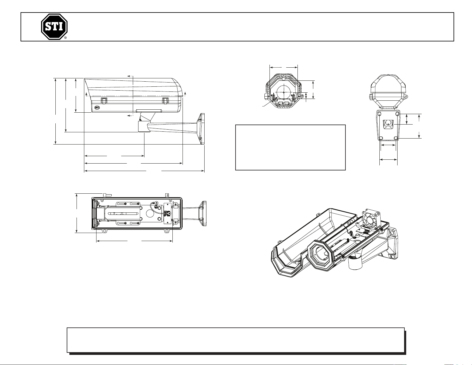
11.56 in.
(295mm)
5.98 in.
(152mm)
9.22 in.
(234mm)
A
15.15 in.
(385mm)
17.12 in.
(435mm)
10.16 in.
(258mm)
8.32 in.
(
211mm)
5
.24 in.
(133mm)
A
B
B
2.35 in.
(60mm)
3.80 in.
(
97mm)
1
.59 in.
(
40mm)
2.81 in.
(71mm)
D
B
C
A
A-A
Safety Technology International, Inc.
2306 Airport Road • Waterford, Michigan 48327-1209
P
hone: 248-673-9898 • Fax: 248-673-1246
T
oll Free: 800-888-4784 • E-mail: info@sti-usa.com
Web: www.sti-usa.com
S
afety Technology International (Europe) Ltd.
Unit 49G Pipers Road • Park Farm Industrial Estate • Redditch
Worcestershire • B98 0HU • England • Tel: 44 (0) 1527 520 999
F
ax: 44 (0) 1527 501 999 • Freephone: 0800 085 1678 (UK only)
E
-mail: info@sti-europe.com • Web: www.sti-europe.com
INSTALLATION OF STI-7150K CCTV HOUSING - DIE CAST HEAVY DUTY
All specifications and information shown were current as of publication, and are subject to change without notice.
B-B
COVER REMOVED
A Overall Width 4.31 in.(109.5mm)
INTERNAL DIMENSIONS
B Maximum Height 2.83 in.(72mm)
C Height from Mounting Base
D Lens Diameter 2.12 in.(54mm)
to Center Lens Opening .97 in.(25mm)
7150K FEB2010
 Loading...