

Page 1
Safety Technology International, Inc.
2306 Airport Road • Waterford, Michigan 48327-1209
Phone: 248-673-9898 • Fax: 248-673-1246
T
oll Free: 800-888-4784 • E-mail: info@sti-usa.com
W
eb: www.sti-usa.com
Safety Technology International (Europe) Ltd.
Unit 49G Pipers Road • Park Farm Industrial Estate • Redditch
Worcestershire • B98 0HU • England • Tel: 44 (0) 1527 520 999
Fax: 44 (0) 1527 501 999 • Freephone: 0800 085 1678 (UK only)
E
-mail: info@sti-europe.com • Web: www.sti-europe.com
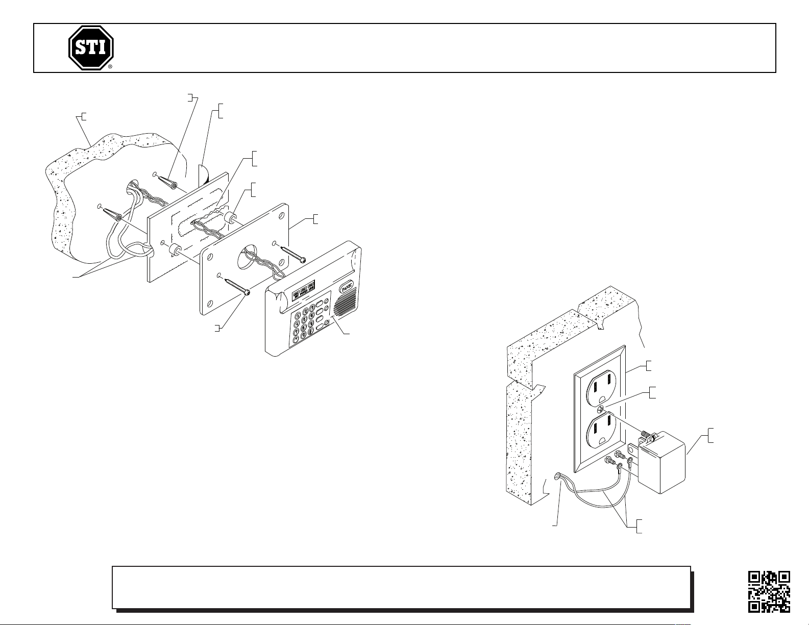
EXISTING 110 VOLT
ELECTRICAL OUTLET
CAUTION - TRANSFORMER MUST BE INSTALLED
INTO OUTLETS HAVING A CENTER SCREW
CLASS 2 - NOT WET
CLASS 3 - WET
TRANSFORMER
TO HEATER ASSEMBLY
WIRE LEADS MAY BE SECURED
TO EITHER MOUNTING TERMINAL
ON TRANSFORMER
TO TRANSFORMER
SENSITIVE ELECTRONIC DEVICE
EXISTING KEYPAD BACKPLATE
(TYPICAL MAY HAVE 2 OR 4 MOUNTING SCREWS)
PRIOR TO FINAL INSTALLATION,
PEEL AND REMOVE FOIL BACKING
ON REAR OF HEAT PAD
IF WIRE OR FASTENER ACCESS
IS NEEDED, CAREFULLY SLIT FOIL
BETWEEN THE HEAT COILS AS SHOWN
NON-FLAMMABLE
EXISTING MOUNTING SURFACE
19014 SCREW 8 x 1 in.
(4) PROIVDED
1
8018 SPACER (4) PROVIDED
MUST BE INSTALLED BETWEEN HEAT PAD
AND BACKPLATE AS SHOWN
19018 ANCHOR
(4) PROVIDED
INSTALLATION INSTRUCTIONS
1. When installing the heater kit, it is important
to place the foil as close as possible to the
electronics you are protecting. The heat
element is designed to keep small areas
warm only, not a large volume area.
2. Peel back adhesive backing and apply heater
foil to nonflammable surface behind
electronic component.
3. Component mounting screws and wires may
pierce the foil heater as shown, but caution is
needed to ensure screws and wires do not
touch heater coil.
STI Heater Kits operate in conjunction with enclosures such as the STI Stopper®II and Mini
Stopper®to protect and help expensive electronic components remain operable in low
temperature areas. They include a foil heater pad with adhesive backing and an internal
thermostat.
Two versions are available: a 12-volt model (shipped with its own 12-volt power supply) and a
24-volt model that is designed to tap directly into a remote power supply. The 12-volt system
(STI-6580) is rated at 25 watts while the 24-volt system (STI-6583) is rated at 8 watts. The STI6580 is designed to maintain a temperature of 33°F (1°C) down to -10°F (-23°C). The STI-6583
is designed only to keep enclosures, etc. from fogging. Use only the STI-6580 for applications
requiring a significant heat source.
• Keeps LCD’s from becoming sluggish and helps them stay visible in subzero
temperatures.
• Allows critical electronic components to operate at low temperatures.
• In tests, STI-6580 maintained 33°F (1°C) at -10°F (-23°C).
• Both 12-volt and 24-volt models available.
• Both models include a one year warranty.
• Temperature control operates only when ambient temperature falls below
40°F (4°C).
• Easy to install and highly effective.
• Can be mounted inside control panels to keep batteries and electronics
warm and operational.
4. Connect the wires from the heater assembly
to a power source having a center screw (see
drawing). STI-6580 is provided with a 12-volt
transformer. STI recommends the usage of 14
AWG wire to connect heater assembly to
transformer. Heater is not polarity sensitive
and you can use either AC or DC power.
5. Mount device backplate over heater using
nylon spacers as required to keep device from
direct contact with heater.
CAUTION: Heater foil is conductive and could
cause electronic device to fail if the foil comes
in contact with exposed wiring or circuitry.
6. Connect electronic device.
Electronic warranty form at www.sti-usa.com/wc14
INSTALLATION OF STI-6580 & STI-6583 HEATER KIT
All specifications and information shown were current as of publication, and are subject to change without notice.
65803IS DEC2007
 Loading...