

Page 1
Safety Technology International, Inc.
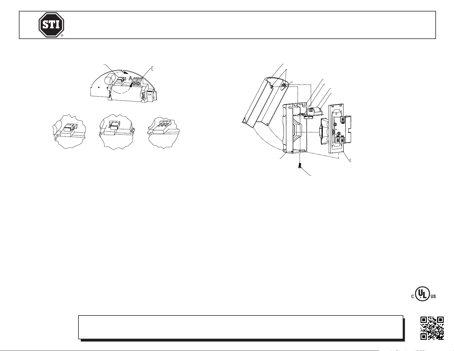
SCREW
STOPPER STATION
CONTACT ASSEMBLY
STOPPER STATION COVER
2306 Airport Road • Waterford, Michigan 48327-1209
Phone: 248-673-9898 • Fax: 248-673-1246
Toll Free: 800-888-4784 • E-mail: info@sti-usa.com
Web: www.sti-usa.com
Safety Technology International (Europe) Ltd.
Unit 49G Pipers Road • Park Farm Industrial Estate • Redditch
Worcestershire • B98 0HU • England • Tel: 44 (0) 1527 520 999
Fax: 44 (0) 1527 501 999 • Freephone: 0800 085 1678 (UK only)
E-mail: info@sti-europe.com • Web: www.sti-europe.com
VOLUME JUMPER
SWITCH TERMINALS
(WIRELESS ONLY)
A
HIGH
LOW
OFF
VIEW A
INSTALLATION
1. Rotate the button lever clockwise to the stop (as shown) so it is pointed toward the inside of the Stopper
Station Shield.
2. With shield rotated to open position (approximately 90° to cover), insert shield pivots into slots on Stopper
Station cover.
3. If desired, insert wires from device switch into PCB terminals and tighten screws. The transmitter for these
terminals must be activated for use. To activate, short the terminals, then install battery. Terminals will
be permanently activated.
4. Place the volume jumper for desired sounder volume (see above).
5. Insert PCB fully into PCB guides. Be sure switch wires are not routed over the battery or button.
6. Rotate cover to closed position.
7. Rotate cover to fully open position then back to closed position to ensure the Button Lever is pressed down
onto the button. (If not, remove PCB and repeat steps 5 and 6.)
8. Pull off the plastic battery tab, leaving the battery installed. (Sounder will be active at this point.)
9. Mount cover with shield onto contact assembly.
10. Install bottom screw to hold cover to contact assembly.
WIRELESS OPERATION
The STI Stopper Station with wireless alert will send two separate wireless signals to an STI Receiver. If both
signals are to be used, each signal must be individually enrolled into the receiver. The first is the Stopper Station
cover signal. This signal is transmitted when the cover is opened and restores the signal to normal when the cover
is closed. The second is the terminal signal. A separate alert signal is sent when the terminal contacts are opened
and restores the signal to normal when the terminal contacts are closed.
To enroll the wireless device signal into the receiver, please see the receiver installation instructions.
STOPPER STATION COVER
STOPPER STATION SHEILD
SHIELD PIVOT
BUTTON LEVER
SCREW
COVER MOUNTING SLOTS
PCB GUIDE
123A LITHIUM BATTERY
SOUNDER/WIRELESS PCB
STOPPER STATION
CONTACT ASSEMBLY
IMPORTANT NOTICE
Changes or modifications not expressly approved by the manufacturer could
void the user’s authority to operate the equipment.
This device complies with Industry Canada license-exempt RSS standard(s).
Operation is subject to the following two conditions: (1) this device may not
cause interference, and (2) this device must accept any interference, including
interference that may cause undesired operation of the device.
Le présent appareil est conforme aux CNR d’Industrie Canada applicables
aux appareils radio exempts de licence. L’exploitation est autorisée aux deux
conditions suivantes: (1) l’appareil ne doit pas produire de brouillage, et (2)
l’utilisateur de l’appareil doit accepter tout brouillage radioélectrique subi,
même si le brouillage est susceptible d’en compromettre le fonctionnement.
Contains FCC ID: TXL34066 IC: 6335A-34066 Model: STI-34066
Electronic warranty form at www.sti-usa.com/wc14
INSTALLATION OF STI-34066 TRANSMITTER AND STI-6517B STOPPER® STATION SHIELD & SOUNDER WITH WIRELESS
All specifications and information shown were current as of publication and are subject to change without notice.
6517B SEPT2012
 Loading...