

Page 1
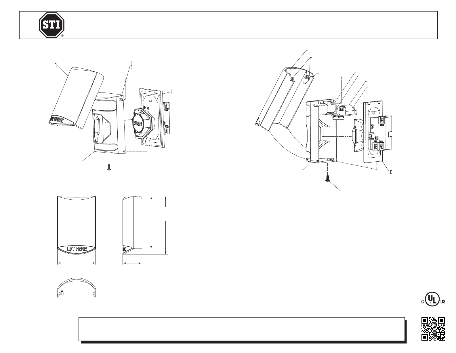
4.84 in.
(123mm)
5.32 in.
(135mm)
1.76 in.
(45mm)
3.51 in.
(89mm)
STOPPER STATION
SCREW
STOPPER STATION
CONTACT ASSEMBLY
SOUNDER PCB
123A LITHIUM BATTERY
PCB GUIDE
COVER MOUNTING SLOTS
BUTTON LEVER
SHIELD PIVOT
STOPPER STATION SHEILD
STOPPER STATION COVER
SHIELD
STOPPER STATION
Safety Technology International, Inc.
2306 Airport Road • Waterford, Michigan 48327-1209
Phone: 248-673-9898 • Fax: 248-673-1246
Toll Free: 800-888-4784 • E-mail: info@sti-usa.com
Web: www.sti-usa.com
STOPPER STATION SHELL
WITH NOTCHED SLOTS
(FOR SHIELD PIVOTS)
SHELL
STOPPER STATION
CONTACT ASSEMBLY
Safety Technology International (Europe) Ltd.
Unit 49G Pipers Road • Park Farm Industrial Estate • Redditch
Worcestershire • B98 0HU • England • Tel: 44 (0) 1527 520 999
Fax: 44 (0) 1527 501 999 • Freephone: 0800 085 1678 (UK only)
E-mail: info@sti-europe.com • Web: www.sti-europe.com
STOPPER STATION SHEILD
SHIELD PIVOT
BUTTON LEVER
STOPPER STATION COVER
COVER MOUNTING SLOTS
PCB GUIDE
123A LITHIUM BATTERY
SOUNDER PCB
STOPPER STATION
CONTACT ASSEMBLY
3.51 in.
(89mm)
INSTALLATION NOTES
SCREW
1. Insert Sounder/Wireless PCB into PCB Card Guides on Stopper Station Cover.
4.84 in.
(123mm)
5.32 in.
(135mm)
2. Orient the Button Lever so it is pointed toward the inside of the Stopper Station Shield Assembly.
3. With Shield Rotated to open position (Approximately 90° to Cover), insert Shield Pivots into Slots on
Stopper Station Cover.
4. Rotate Cover to Closed Position.
5. Rotate Cover to fully open position, back to closed position, and ensure the Button Level is pressed
down onto the button. If not, repeat steps 2-5.
6. Program the sounder volume on or off by pulling off the plastic battery tab with the battery remaining
installed. (Sounder will be on at this point)
7. The sounder volume programming cycle is ON for 10 seconds, OFF for 10 seconds, and then defaults to
1.76 in.
(45mm)
ON. To set volume: open the Shield, close, open again and close again.
NOTE: Remove and replace battery to reset volume setting.
8. Mount Shield, Cover and PCB Assembly onto Stopper Station Button Assembly.
9. Install Screw to Hold Cover to Button Assembly.
Electronic warranty form at www.sti-usa.com/wc14
INSTALLATION OF STI-6517 STI STOPPER® STATION SHIELD
All specifications and information shown were current as of publication and are subject to change without notice.
6517 MARCH2010
 Loading...