

Page 1
Safety Technology International, Inc.
2306 Airport Road • Waterford, Michigan 48327-1209
Phone: 248-673-9898 • Fax: 248-673-1246
Toll Free: 800-888-4784 • E-mail: info@sti-usa.com
Web: www.sti-usa.com
Safety Technology International (Europe) Ltd.
Unit 49G Pipers Road • Park Farm Industrial Estate • Redditch
Worcestershire • B98 0HU • England • Tel: 44 (0) 1527 520 999
Fax: 44 (0) 1527 501 999 • Freephone: 0800 085 1678 (UK only)
E-mail: info@sti-europe.com • Web: www.sti-europe.com
FEMALE JACK
MALE PLUG
ZONE ALERT LED
FEMALE JACK
MALE PLUG
24” 4-CONDUCTOR CABLE
(1) PROVIDED
POWER IN 12 VDC
250 mA
ZONE ALERT LED
5.90 in.
(150mm)
2.00 in.
(51mm)
+
_
FOR BOTH ENDS OF
CONNECTOR ALIGN TABS
ON MALE PLUG TO SLOTS
ON FEMALE JACK
AND INSERT AS SHOWN.
Zone 5
Zone 6
Zone 7
Zone 8
Zone 1
Zone 2
Zone 3
Zone 4
NO C NC NO C NC
NO C NC
NO C NC
NO C NC NO C NC
NO C NC
NO C NC12V GND
Safety Technology International, Inc.
2306 Airport Road • Waterford, Michigan 48327-1209
Phone: 248-673-9898 • Fax: 248-673-1246
Toll Free: 800-888-4784 • E-mail: info@sti-usa.com
Web: www.sti-usa.com
Zone 2
Zone 1
NO C NC NO C NC
ADHESIVE BACK PCB SUPPORT
(4) PROVIDED
NO C NC
POWER IN 12 VDC
250 mA
PEEL BACKING
Zone 3
+
Zone 4
NO C NC
_
5.90 in.
(150mm)
Safety Technology International (Europe) Ltd.
Unit 49G Pipers Road • Park Farm Industrial Estate • Redditch
Worcestershire • B98 0HU • England • Tel: 44 (0) 1527 520 999
Fax: 44 (0) 1527 501 999 • Freephone: 0800 085 1678 (UK only)
E-mail: info@sti-europe.com • Web: www.sti-europe.com
Zone 5
NO C NC NO C NC
Zone 7
NO C NC
Zone 8
NO C NC12V GND
Zone 6
24” 4-CONDUCTOR CABLE
(1) PROVIDED
FEMALE JACK
MALE PLUG
2.00 in.
(51mm)
FOR BOTH ENDS OF
CONNECTOR ALIGN TABS
ON MALE PLUG TO SLOTS
ON FEMALE JACK
AND INSERT AS SHOWN.
TO 8 CHANNEL RECEIVER
STI-34108
INSTALLATION INSTRUCTIONS
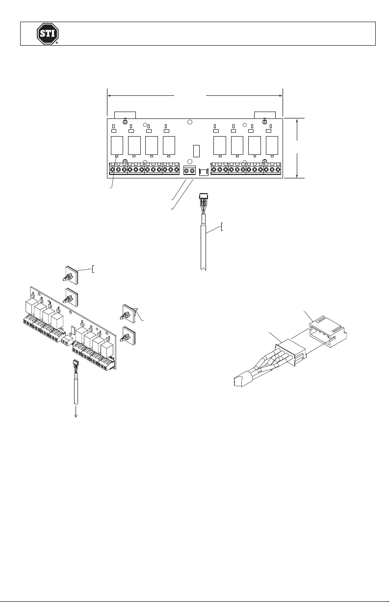
1. Snap adhesive back PCB supports into PCB as shown.
2. Peel backing from adhesive back PCB supports, place
PCB in desired position and press firmly.
INSTALLATION OF STI-34188 8-ZONE RELAY BOARD
All specifications and information shown were current as of publication and are subject to change without notice.
STI-34188 JUNE 2012
Page 2
Safety Technology International, Inc.
Safety Technology International, Inc.
2306 Airport Road • Waterford, Michigan 48327-1209
Phone: 248-673-9898 • Fax: 248-673-1246
Toll Free: 800-888-4784 • E-mail: info@sti-usa.com
Web: www.sti-usa.com
Safety Technology International (Europe) Ltd.
Unit 49G Pipers Road • Park Farm Industrial Estate • Redditch
Worcestershire • B98 0HU • England • Tel: 44 (0) 1527 520 999
Fax: 44 (0) 1527 501 999 • Freephone: 0800 085 1678 (UK only)
E-mail: info@sti-europe.com • Web: www.sti-europe.com
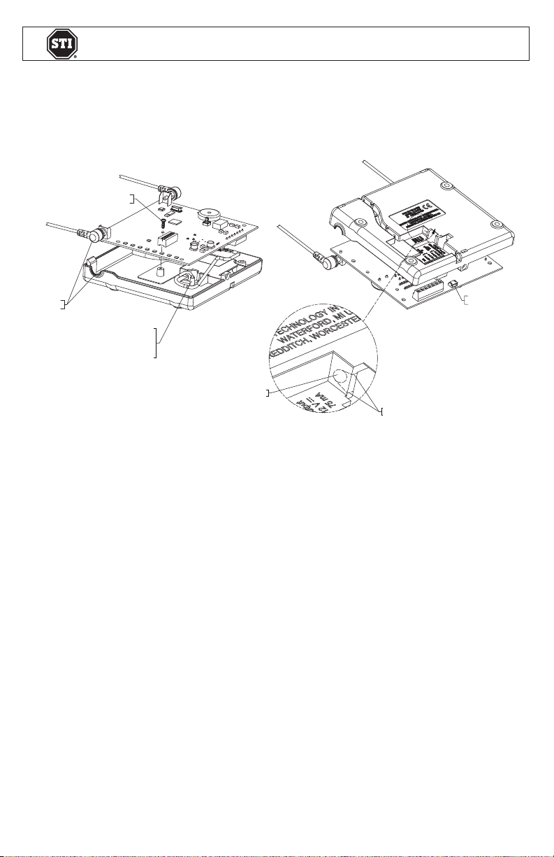
A
AFTER DRILLING, CUT OUT THIS AREA
USING SIDE CUTTERS OR KNIFE
CABLE JACK TO RELAY BOARD
DRILL 5/32 in. (4mm)
DIAMETER HOLE
BE SURE TO ROUTE
CABLE AROUND POST AS
SHOWN AND PLUG
CABLE IN TO CONNECTOR
CIRCUIT BOARD MOUNTING SCREW
DETAIL A
ALIGN TO
ASSEMBLE
2306 Airport Road • Waterford, Michigan 48327-1209
Phone: 248-673-9898 • Fax: 248-673-1246
Toll Free: 800-888-4784 • E-mail: info@sti-usa.com
Web: www.sti-usa.com
Safety Technology International (Europe) Ltd.
Unit 49G Pipers Road • Park Farm Industrial Estate • Redditch
Worcestershire • B98 0HU • England • Tel: 44 (0) 1527 520 999
Fax: 44 (0) 1527 501 999 • Freephone: 0800 085 1678 (UK only)
E-mail: info@sti-europe.com • Web: www.sti-europe.com
ALIGN TO
ASSEMBLE
CIRCUIT BOARD
MOUNTING SCREW
BE SURE TO ROUTE
CABLE AROUND POST AS
SHOWN AND PLUG
CABLE IN TO CONNECTOR
DRILL 5/32 in. (4mm)
DIAMETER HOLE
DETAIL A
A
AFTER DRILLING, CUT OUT THIS AREA
USING SIDE CUTTERS OR KNIFE
CABLE JACK
TO RELAY BOARD
CABLE INSTALLATION TO RECEIVER
1. Remove circuit board from base by removing circuit board mounting screw.
2. Drill 5/32 in. diameter hole in base as shown (circuit board must be removed.)
3. After drilling, cut out area as shown using side cutters or knife.
4. Route cable as shown and connect cable to jack on circuit board.
5. While replacing circuit board, gently pull cable from bottom of base to take up any
slack in cable occurred during installation.
SPECIFICATIONS
• Standby: 12 VDC; 0.01mA
• Max Operating: 12 VDC; 164mA
• Form “C” Contact Rating (resistive): 120 VAC, 3A; 28 VDC, 3A
WARRANTY
One year warranty on electro mechanical and electronic components.
Electronic warranty form at www.sti-usa.com/wc14.
INSTALLATION OF STI-34188 8-ZONE RELAY BOARD
All specifications and information shown were current as of publication and are subject to change without notice.
STI-34188 JUNE 2012
 Loading...