

Page 1
QUICK SETUP GUIDE
APPROXIMATE GAP (1 INCH)
GAP MAY BE EFFECTED
IF MOUNTED ON METAL.
“ALERT”
OPENED
APPROXIMATE GAP (1 INCH)
GAP MAY BE EFFECTED
IF MOUNTED ON METAL.
REED SWITCH CABLE
(18 INCHES)
APPROXIMATE GAP
(GREATER THAN 1 1/3 INCHES)
GAP MAY BE EFFECTED
IF MOUNTED ON METAL.
“RESTORE”
“ALERT”
OPENED
APPROXIMATE GAP
(GREATER THAN 1 1/3 INCHES)
GAP MAY BE EFFECTED
IF MOUNTED ON METAL.
J2
“RESTORE”
CLOSED
“ALERT”
OPEN
MAGNETIC SENSOR
“RESTORE”
TILT SENSOR
“ALERT”
“RESTORE”
BOTTOM
SENSOR TRANSMITTER BOTTOM
SCREWS
RECHARGEABLE NiMH BATTERIES
H
L
SENSITIVITY JUMPERS
(SOLAR TYPE)
SENSITIVITY JUMPERS
(BATTERY TYPE)
H
L
REMOVE PLASTIC TAB
FROM BATTERIES
DRIVEWAY
PLACE SENSOR
TRANSMITTER 3' OR
LESS FROM EDGE OF
DRIVEWAY AND 25+
FEET OR MORE FROM
STREET.
25' OR MORE
3' OR
LESS
12'
MAX
B
H
L
FINGER NOTCHES
DO NOT
PULL ANTENNA!
WALL MOUNT (INCLUDED)
NOT NEEDED FOR POLE
MOUNT INSTALLATION
SENSITIVITY
ADJUSTMENT
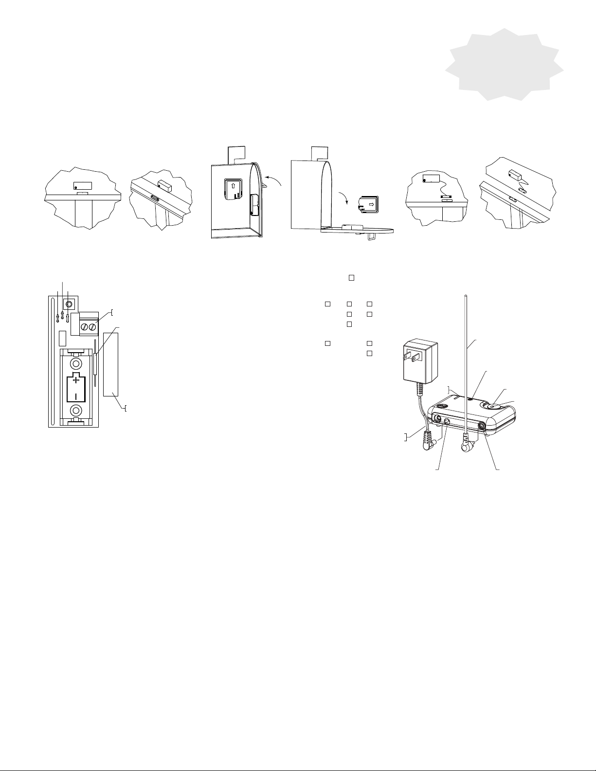
STI-34401 Universal Sensor
TO SETUP:
1. Open cover. Remove battery isolator strip.
2. Configure jumpers - select one of the following: magnetic sensor, tilt sensor, external terminals.
3. Replace cover.
4. Program into receiver.
5. Mount where needed.
MAGNETIC SENSOR
With 4-Channel Receiver
TILT SENSOR
Program sensor
before installation
EXTERNAL TERMINALS
“RESTORE”
CLOSED
CONFIGURE JUMPERS:
J3
J1
EXTERNAL SWITCH
CONNECTION BLOCK
ONBOARD REED SWITCH
LOCATION FOR
MAGNETIC SENSOR
“ALERT”
OPEN
“RESTORE”
“ALERT”
Cut jumpers with “X”, do not cut jumpers with “ .“
Magnetic Sensor (supervised)
Tilt Sensor (supervised)
External Terminals (supervised)
Magnetic Sensor (not supervised)
Tilt Sensor (not supervised)
External Terminals (not supervised)
J1 J2 J3
X
X X
X
X X
X X X
NOTE: To ensure jumpers do not reattach or short to other
components, cut both jumper leads flush to PCB and remove
“RESTORE”
CLOSED
GREEN
LED
“ALERT”
OPEN
RECEIVER ANTENNA
SPEAKER
BUTTON
RED LED
jumper wire.
PROGRAM 4-CHANNEL RECEIVER WITH SENSOR:
Please read this section completely before proceeding.
1. Plug antenna into the antenna (red) connector on the receiver.
TRANSISTOR
OUTPUT JACK
POWER CONNECTOR ANTENNA CONNECTOR
4 CHANNEL RECEIVER
2. Plug adapter into the wall.
3. While holding down the gray button, plug the adapter into the 4-Channel Receiver. A series of beeps/tones will begin playing. Release
button when beeps/tones finish. The red and green LED’s will flash quickly. The receiver is now in program mode and you have 1 minute to program
all sensors.
4. Activate a sensor to program into 4-Channel (refer to your sensor instructions). A tone or series of beeps will sound representing the channel the
sensor programmed into (i.e.: one beep is zone 1, two beeps is zone 2, etc.).
5. If more sensors are to be programmed, repeat step 4.
6. After programming sensor(s), wait a minimum of 5 seconds, press gray button to exit Program Mode or receiver will exit program mode automatically
within one minute.
CHECK SENSOR:
1. Trigger the sensor. Receiver will emit the alert tone and red light will flash. For multiple sensors, the receiver will beep a number of times (for the
number of the sensor, 1 through 4) and play the alert tone.
2. If red light flashes but there is no tone, the receiver is in silent mode. To exit silent mode press and hold the button until you hear a single beep
then release. Repeat step 6 to hear the receiver alert tone.
CLEAR SENSOR FROM 4-CHANNEL RECEIVER:
1. Disconnect power from receiver and wait approximately 15 seconds.
2. Reconnect power to the receiver, the receiver will make a start-up tone. The green LED will be solid.
3. Within 3 seconds press and hold down the gray button, you will hear a series of beeps/tones. When you hear a continuous tone, let go of the
button; the sensors are cleared.
For additional features and instructions refer to full instruction manual provided with your product.
12/12
Page 2
QUICK SETUP GUIDE
APPROXIMATE GAP (1 INCH)
GAP MAY BE EFFECTED
IF MOUNTED ON METAL.
“ALERT”
OPENED
APPROXIMATE GAP (1 INCH)
GAP MAY BE EFFECTED
IF MOUNTED ON METAL.
REED SWITCH CABLE
(18 INCHES)
APPROXIMATE GAP
(GREATER THAN 1 1/3 INCHES)
GAP MAY BE EFFECTED
IF MOUNTED ON METAL.
“RESTORE”
“ALERT”
OPENED
APPROXIMATE GAP
(GREATER THAN 1 1/3 INCHES)
GAP MAY BE EFFECTED
IF MOUNTED ON METAL.
“RESTORE”
CLOSED
“ALERT”
OPEN
MAGNETIC SENSOR
“RESTORE”
TILT SENSOR
“ALERT”
“RESTORE”
EXTERNAL TERMINALS
“RESTORE”
CLOSED
“ALERT”
OPEN
(DOUBLE SIDED FOAM TAPE)
“ALERT”
VINYL ELECTRICAL
TAPE
19039 SCREW
(2) PROVIDED
KNOCK OUT FOR WIRES
OF EXTERNAL SWITCH
EXTERNAL SWITCH
CONNECTION BLOCK
TAMPER SWITCH
ONBOARD
REED SWITCH
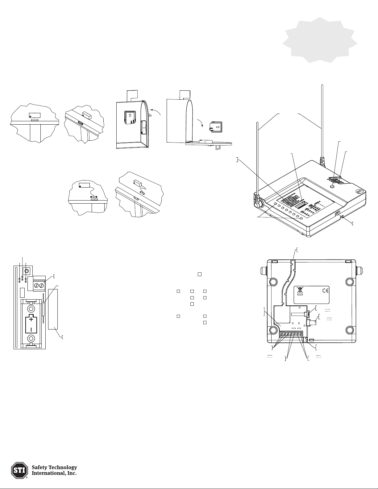
OPTION 1 MOUNTING
(DOUBLE SIDED FOAM TAPE)
OPTION 2 MOUNTING
VINYL ELECTRICAL
TAPE
19039 SCREW
(2) PROVIDED
KNOCK OUT FOR WIRES
OF EXTERNAL SWITCH
EXTERNAL SWITCH
CONNECTION BLOCK
TAMPER SWITCH
ONBOARD
REED SWITCH
MULTLIPLE SYSTEMS
Receiver
Receiver
SINGLE SYSTEM
ANTENNAS
SWITCHES 1-8
ZONE LEDs
PUSH BUTTON
PIEZO
COVER
SCREW
STI-34401 Universal Sensor
TO SETUP:
1. Open cover. Remove battery isolator strip.
2. Configure jumpers - select one of the following: magnetic sensor, tilt sensor, external terminals.
3. Replace cover.
4. Program into receiver.
5. Mount where needed.
MAGNETIC SENSOR
“RESTORE”
CLOSED
“ALERT”
OPEN
EXTERNAL TERMINALS
With 8-Channel Receiver
TILT SENSOR
“RESTORE”
“ALERT”
DIPSWITCH
FUNCTIONS
ANTENNAS
SWITCHES 1-8
Program sensor
before installation
PUSH BUTTON
PIEZO
“RESTORE”
CLOSED
CONFIGURE JUMPERS:
J2
J3
J1
EXTERNAL SWITCH
CONNECTION BLOCK
ONBOARD REED SWITCH
Cut jumpers with “X”, do not cut jumpers with “ .“
“ALERT”
OPEN
Magnetic Sensor (supervised)
Tilt Sensor (supervised)
External Terminals (supervised)
Magnetic Sensor (not supervised)
Tilt Sensor (not supervised)
External Terminals (not supervised)
LOCATION FOR
MAGNETIC SENSOR
NOTE: To ensure jumpers do not reattach or short to other
components, cut both jumper leads flush to PCB and remove
jumper wire.
PROGRAM 8-CHANNEL RECEIVER WITH SENSOR:
J1 J2 J3
X
X X
X
X X
X X X
ZONE LEDs
EMBOSSED
INPUT AND
OUTPUTS
SWITCH OUTPUTS
TERMINALS 500mA
FORM C
12V INPUTS
WIRE ROUTE
OPTION 1
FCC ID: TXL34108
MODEL #34108
IC: 6335A-34108
WATERFORD, MI U.S.A.
75mA
12 V
Output
300 mA
12 V 500mA
PLUG IN ADAPTER
- OUT
+ 12 V
12V OUTPUTS
TERMINALS 300mA
TRIGGERED OUTPUT PLUG
12V , 75mA
PLUG IN ADAPTER
12V , 500mA
WIRE ROUTE
OPTION 2
SAFETY TECHNOLOGY INTERNATIONAL
REDDITCH, WORCESTERSHIRE UK
Trigger
500 mA
N.C.
COM
N.O.
- IN
+ 12 V
8 CHANNEL RECEIVER
COVER
SCREW
Please read this section completely before proceeding.
1. Set switch 2 to ON. LED in first available zone flashes green.
2. If zone latching is required, set dip switch 3 ON. Refer to full instructions manual for more information, page 5.
3. Trigger the sensor and then restore. A double beep will sound when the receiver detects the sensor, the zone LED turns red and the next available
zone flashes green. If using multiple sensors (up to 8), trigger each sensor. When finished programming, set switch 2 to OFF. Only programmed
zones will have lighted LEDs. Once programmed, if power is lost, you will not need to reprogram.
CHECK SENSOR:
1. Trigger the sensor. Receiver turns that zone’s LED continuous red.
2. Write an identifying name for each sensor on the lined paper provided.
CLEAR SENSOR FROM 8-CHANNEL RECEIVER:
Refer to full instructions manual, page 7.
P: 248-673-9898
www.sti-usa.com
Electronic warranty form at www.sti-usa.com/wc14
For additional features and instructions refer to full
instruction manual provided with your product.
6/13
 Loading...