

Page 1
Installation and Operation Manual
MOUNTING
TUBE CAP
WALL MOUNT (INCLUDED)
NOT NEEDED FOR POLE
MOUNT INSTALLATION
2 “C” BATTERIES
(NOT INCLUDED)
SENSOR TRANSMITTER
MOUNTING TUBE
MOUNTING STAKE
SENSOR TRANSMITTER
BOTTOM
SENSOR TRANSMITTER
MOUNTING
TUBE CAP
MOUNTING TUBE
MOUNTING STAKE
FINGER
NOTCHES
DRIVEWAY
3’OR
LESS
25' OR MORE
PLACE SENSOR
TRANSMITTER 3' OR
LESS FROM EDGE OF
DRIVEWAY AND 25'
OR MORE FROM STREET.
12’
MAX
STI 4-Channel Receiver
Model: STI-34104
Thank you for purchasing the STI 4-Channel Receiver. Your satisfaction is very important to us.
Please read this manual carefully to get the most from your new product.
How the Product Works:
STI offers multiple wireless products designed to alert you of several different conditions. The
4-Channel Receiver allows you to monitor up to 4 different STI devices at a single convenient
location. The STI wireless alert series uses a system to ensure other non STI devices are
enrolled or detected (eliminating accidental enrollment, alerts or crosstalk). The STI 4-Channel
Receiver allows you to sound a chime, mute the chime to monitor in silence mode or turn on
an external 12 VDC output. It also uses alert latching which will keep the alert indicator on if
the SENSOR is still in the alert state.
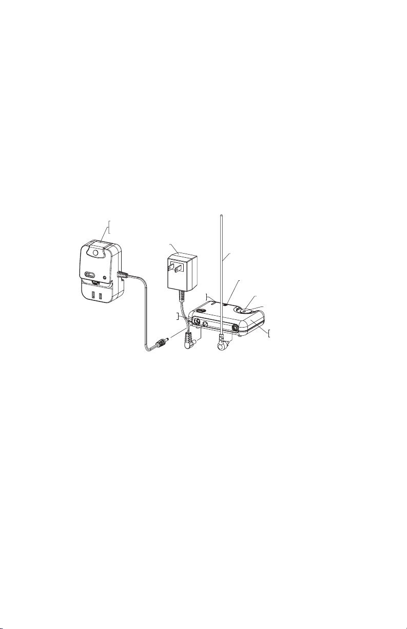
Before You Start:
Refer to this drawing to become familiar with all parts.
STI-30104
LAMP CONTROLLER
(OPTIONAL)
AC ADAPTER
75 mA
OUTPUT
GREEN
LED
RECEIVER ANTENNA
SPEAKER
BUTTON
RED LED
STI-34104
INDOOR RECEIVER
4-Channel Receiver STI-34104
Receives up to 4 different STI Wireless Alert Series Sensors
Clearing the RECEIVER memory:
Follow before using the RECEIVER for the first time or if RECEIVER does not respond as
expected. Programmed devices will always remain in memory, unless this procedure is
followed (even if power is lost).
1. Be sure the antenna is in the red connector on the RECEIVER.
2. Disconnect power from RECEIVER and wait for 15 seconds.
3. Reconnect power to the RECEIVER, the RECEIVER will make a start up tone and the green
LED will flash.
4. Immediately press (RECEIVER will beep)
and hold
the grey button. You will hear a second
single beep (approx. 2-3 seconds). Continue to hold (approx. 3 more seconds) until you
hear a double beep, then let go of the button. The red LED should be solid.
5. Press and hold the button again until you hear a long tone, then let go of the button.
NOTE: if you do not get the long tone (example, short beep) then begin again at step 2 until
the long tone is heard.
6. Disconnect power and wait another 15 seconds prior to following ENROLL A SENSOR.
— 1 —
Page 2

Enroll a SENSOR:
These steps should be followed to program devices into the RECEIVER.
1. Plug antenna into red connector on the RECEIVER.
2. Plug in the RECEIVER and
3. Immediately press (RECEIVER will beep)
single beep (approx. 2-3 seconds), then let go of the button.
4. The red LED should be solid. You now have 60 seconds to enroll all SENSORS.
5. Trigger a SENSOR (examples: open cover, separate reed switch, tilt, etc.). When the
wireless signal is received the green LED on the RECEIVER flashes and the RECEIVER
makes a double beep. If you have additional sensors, repeat this step. When you have
enrolled all SENSORS go to Step 6.
6. To exit enroll mode, press and release the button on the RECEIVER.
7. Test a SENSOR by triggering the SENSOR. The RECEIVER should beep once, twice, etc.
then make the alert tone. If your RECEIVER does not respond correctly after these steps,
follow the steps in the section named “Clearing the RECEIVER memory” and “Enroll a
SENSOR.”
wait until the start up tone finishes
and hold
the grey button until you hear a second
.
RECEIVER Modes of Operation:
Normal Operating Mode
When signal is received from a device, a short alert tone will play and the red LED on the
RECEIVER will flash (until a restore signal is received from the device and the RECEIVER is
reset). The green LED may flash periodically to indicate routine signals are being received. This
does not mean a device has been triggered.
To reset the RECEIVER, press and release the button. If more than one SENSOR is being used
and is triggered, the RECEIVER will beep twice, three times, etc. before playing the alert tone
to indicate which SENSOR was detected by the RECEIVER.
Temporary (8 Hours) and Permanent Silent Modes
These modes may be entered ONLY while the RECEIVER is in normal operating mode. Once
in silent mode, if there is a power outage, the RECEIVER will stay in silent mode until exited.
While in silent mode, the red LED will change from continuous to flashing when a transmission
is detected.
Entering Temporary Silent Mode - Press and hold the button on the RECEIVER until you hear
a second beep (approximately 3 seconds). Red LED will be on solid.
Entering Permanent Silent Mode - Press and hold the button until the RECEIVER makes a
series of two short beeps (approximately 6 seconds). Red LED will be on solid.
Exit Silent Mode - Push and hold the button until you hear a single beep to return to normal
operating mode.
— 2 —
Page 3

Low Battery / Tamper / Out of Range Alert:
For any of the following conditions, the RECEIVER annunciates once per minute with a number
of beeps indicating which SENSOR has trouble (i.e. 1 beep for the first, 2 beeps for the second,
etc.)
1. SENSOR has a low battery
2. Something has triggered the tamper signal on SENSOR
3. SENSOR has been out of range (between 12 - 24 hours)
This will continue until either:
1. The RECEIVER gets a normal operation message from the SENSOR
2. SENSOR is cleared from RECEIVER memory
Transistor Output Jack:
This output can trigger a low powered device such as a relay or the STI Lamp Controller (STI-
30104). The output is a 3.5mm mono jack and is polarity sensitive. Output will supply 75mA
at 12VDC for three seconds.
Optional Lamp Controller Accessory:
The lamp controller plugs into the transistor output jack and will turn on a lamp any time your
SENSOR is triggered. Never come home to a dark house again, and let others think you are
home when you aren’t.
Trouble Shooting Tips:
The RECEIVER does not power up (green LED is off)
1. Check the AC power outlet for power
2. Check that the AC Adapter is plugged into both the RECEIVER and wall outlet
3. Try another AC adapter (12V DC 100mA only) with a +12 VDC center and -12 VDC outside
edge
The RECEIVER does not sound when a SENSOR alert is triggered
1. Check that the RECEIVER is not in Temporary or Permanent Silent Mode
2. Check if the RECEIVER is sounding a SENSOR alert (1/minute)
3. Trigger the SENSOR to check that the SENSOR and RECEIVER are within operating
distance from each other
4. Check the SENSOR batteries and replace if necessary
5. Reprogram the RECEIVER using the steps in “Clearing the RECEIVER memory” and
“Enroll a SENSOR”
The RECEIVER sounds when there should be no alert from the SENSOR
1. Check that the SENSOR is mounted firmly with the correct orientation
2. Reprogram the RECEIVER using the steps in “Clearing the RECEIVER memory” and
“Enroll a SENSOR”
The RECEIVER sounds when lightning strikes
1. This may occur in severe weather, especially for SENSOR’s mounted outside
The RECEIVER gives short beeps
1. Trigger the SENSOR to check that it is not too far away from the RECEIVER
2. Check that the SENSOR is not damaged
3. Replace the batteries in the SENSOR
— 3 —
Page 4

Important Notice:
This product has been tested and complies with the specifications for a Class B digital device, pursuant to Part 15 of the
FCC Rules.
These limits are designed to provide reasonable protection against harmful interference in a residential installation. This
equipment generates, uses, and can radiate radio frequency energy and, if not installed and used according to the
instructions, may cause harmful interference to radio communications. However, there is no guarantee that interference
will not occur in a particular installation. If this equipment does cause harmful interference to radio or television reception,
which is found by turning the equipment off and on, the user is encouraged to try to correct the interference by one or
more of the following measures:
-Reorient or relocate the receiving antenna
-Increase the separation between the equipment or devices
-Connect the equipment to an outlet other than the RECEIVER’s
-Consult a dealer or an experienced radio/TV technician for assistance
Operation is subject to the following two conditions: (1) this device may not cause interference, and (2) this device
must accept any interference, including interference that may cause undesired operation of the device. Changes or
modifications not expressly approved by Safety Technology International, Inc. could void your authority to operate this
equipment.
To reduce potential radio interference to other users, the antenna type and its gain should be so chosen that the equivalent
isotropically radiated power (e.i.r.p.) is not more than that permitted for successful communication.
Model: 34104 IC: 6550A-34104
FCC ID: TXL34104
Warnings:
FOR INDOOR USE ONLY. This unit CANNOT be used with 3-prong grounded plugs. Do not connect RECEIVER
to any heat producing device. Keep RECEIVER away from water and/or damp areas. To prevent electric
shock, match wide blade of plug to the wide slot of outlet and insert completely.
When using lamp controller option, use ONLY 200 Watt or less incandescent lamps, and keep lamp away from
bed coverings, curtains or other flammable materials as this may present a fire hazard.
Warranty Information:
Safety Technology International, Inc. warrants to the original consumer/purchaser that this
product shall be free of defects in material and workmanship under normal use and circumstances
for a period of one (1) year from the original date of purchase.
Technical support:
Contact STI at 800-888-4784 ext 202.
Accessories:
STI-34201 Wireless Mailbox Alert Sensor
STI-34301 Wireless Garage Sentry Sensor
STI-34401 Wireless Universal Alert Sensor
STI-34501 Wireless Pool Access Sensor
STI-34101 Solar Powered Driveway Monitor Sensor
STI-34151 Battery Powered Driveway Monitor Sensor
STI-34104 4-Channel Receiver
STI-34108 8-Channel Receiver
STI-34106 Keyfob
STI-34105 Voltamax 12 VDC (500mA) Power Supply
STI-30104 Lamp Controller
STI-30105 Extended Antenna
Safety Technology International, Inc.
2306 Airport Rd • Waterford, MI 48327
Phone: 248-673-9898 • Fax: 248-673-1246
info@sti-usa.com • www.sti-usa.com
Safety Technology International (Europe) Ltd.
Unit 49G Pipers Road • Park Farm Industrial Estate • Redditch
Worcestershire • B98 0HU • England • Tel: 44 (0) 1527 520 999
Fax: 44 (0) 1527 501 999 • Freephone: 0800 085 1678 (UK only)
E-mail: info@sti-europe.com • Web: www.sti-europe.com
Install 34104 03/11
 Loading...