

Page 1
Safety Technology International, Inc.
“EZ” MOUNT TABS
DETAIL A
BOTTOM
CUTOUT EDGE
A
A/C UNIT
INSTALL GASKET PROVIDED
ENCLOSURE SHOWN
WITH DOOR REMOVED
1/4 - 20 x 3/4 in. BOLT
(4) PROVIDED
LOCK WASHER
(4) PROVIDED
REMOVE THE (4) SCREWS AND
FRONT COVER TO OBTAIN ACCESS
TO TEMPERATURE CONTROLS.
(SEE INSTRUCTION MANUAL FOR DETAILS)
FRONT COVER
INLET AIR FILTER
REMOVE TO CLEAN.
(SEE INSTRUCTION MANUAL)
TEMPERATURE
CONTROLS
2306 Airport Road • Waterford, Michigan 48327-1209
Phone: 248-673-9898 • Fax: 248-673-1246
Toll Free: 800-888-4784 • E-mail: info@sti-usa.com
Web: www.sti-usa.com
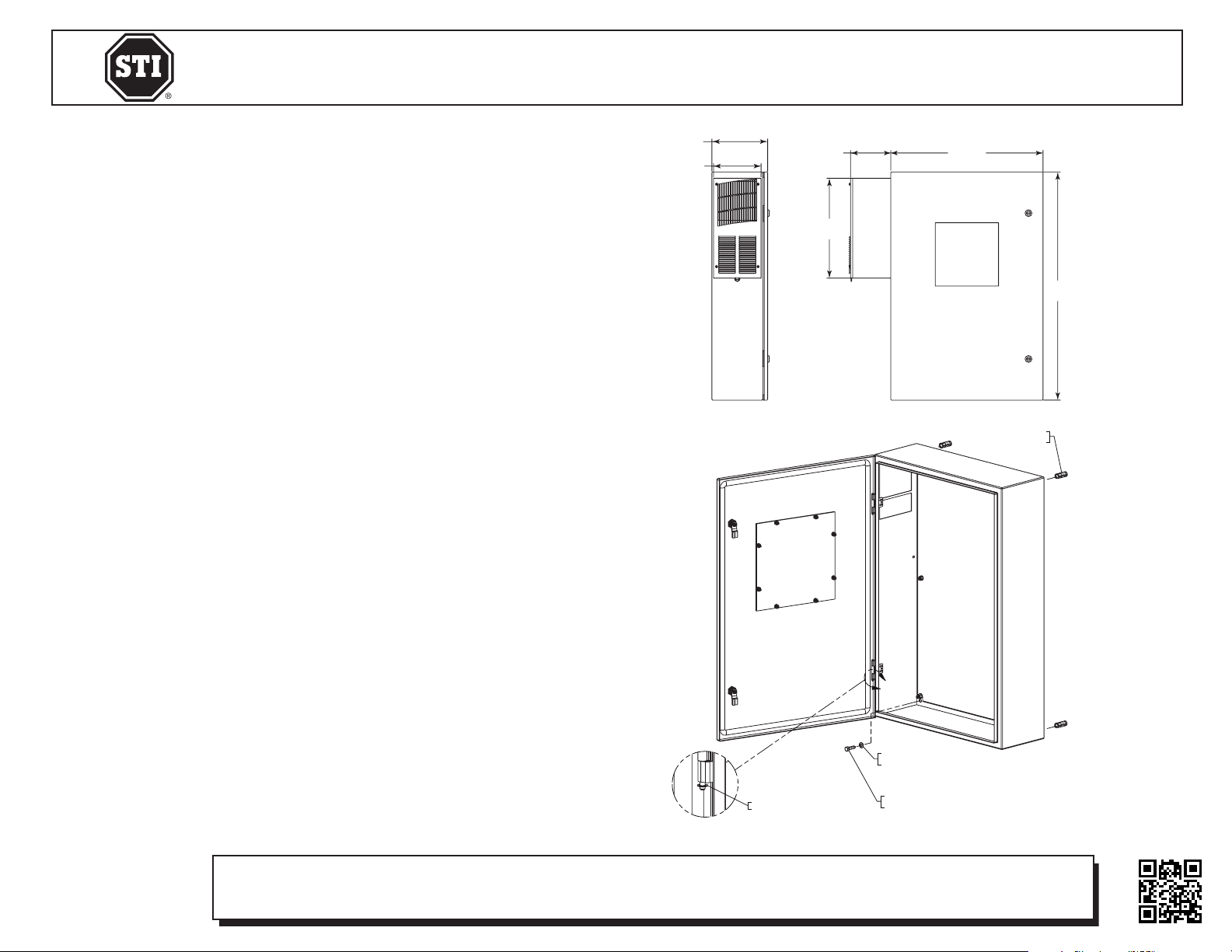
8.79 in.
(223mm)
7.5 in.
(191mm)
Safety Technology International (Europe) Ltd.
Unit 49G Pipers Road • Park Farm Industrial Estate • Redditch
Worcestershire • B98 0HU • England • Tel: 44 (0) 1527 520 999
Fax: 44 (0) 1527 501 999 • Freephone: 0800 085 1678 (UK only)
E-mail: info@sti-europe.com • Web: www.sti-europe.com
6.35 in.
(161mm)
24 in.
(610mm)
NOTE:
If mounting to brick, block or concrete wall, drill 5/8” diameter
holes 2” deep and insert lag shields.
If mounting to wood wall or wood stud, drill 9/32” diameter holes
1-1/2” deep.
INSTALLATION INSTRUCTIONS
1. Using needle-nose pliers remove both hinge pin snap rings.
2. Push out or lift out hinge pins and remove door.
3. Place enclosure on wall and mark top right hole position onto
wall. Set enclosure aside.
4. Drill hole according to note above.
5. Insert lag screw into sealing washer. Place enclosure on wall and
insert lag screw with sealing washer through enclosure and into
drilled hole. Finger tighten only.
6. Allow enclosure to pivot and hang from lag screw.
7. Set a level on top of enclosure and level enclosure. Mark the
remaining three mounting holes onto wall.
8. Allow enclosure to pivot and hang from lag screw and drill the
remaining three holes.
9. Insert the remaining three lag screws with sealing washers
through enclosure into wall and tighten all (4) lag screws.
15.75 in.
(400mm)
19105 3/8 LAG SHIELD
(4) PROVIDED
36 in.
(914mm)
Electronic warranty form at www.sti-usa.com/wc14
STI-7560AC ENCLOSURE MOUNTING INSTRUCTIONS
All specifications and information shown were current as of publication and are subject to change without notice.
DETAIL A
HINGE PIN SNAP RING
(ONE ON EACH HINGE PIN)
A
19106 SEALING WASHER
(4) PROVIDED
19104 3/8 x 1-1/2 LAG SCREW
(4) PROVIDED
7560AC OCT2010
Page 2
Safety Technology International, Inc.
2306 Airport Road • Waterford, Michigan 48327-1209
Phone: 248-673-9898 • Fax: 248-673-1246
Toll Free: 800-888-4784 • E-mail: info@sti-usa.com
Web: www.sti-usa.com
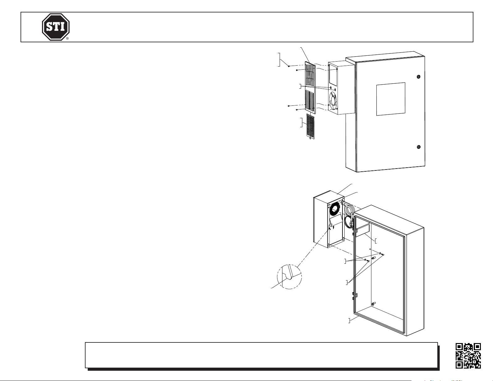
After enclosure has been mounted to the wall, the A/C
unit can be mounted to the enclosure.
INSTALLATION NOTES
1. Read and understand instruction manual before
mounting and operating A/C unit.
2. Install gasket provided on to A/C unit.
3. Insert power cord and wires through top cutout in
enclosure.
4. Mount A/C unit to enclosure by resting EZ mount tabs
on bottom cutout edge. This will hold A/C unit in
place while bolts are inserted.
5. Insert the (4) 1/4 - 20 x 3/4 inch bolts with lock
washers. Make sure the threads of all (4) bolts have
engaged with the A/C unit before tightening.
6. Tighten the 4 bolts evenly.
7. Replace door, hinge pins and hinge pin snap rings.
REMOVE THE (4) SCREWS AND
FRONT COVER TO OBTAIN ACCESS
(SEE INSTRUCTION MANUAL FOR DETAILS)
TO TEMPERATURE CONTROLS.
REMOVE TO CLEAN.
(SEE INSTRUCTION MANUAL)
FRONT COVER
TEMPERATURE
CONTROLS
INLET AIR FILTER
Safety Technology International (Europe) Ltd.
Unit 49G Pipers Road • Park Farm Industrial Estate • Redditch
Worcestershire • B98 0HU • England • Tel: 44 (0) 1527 520 999
Fax: 44 (0) 1527 501 999 • Freephone: 0800 085 1678 (UK only)
E-mail: info@sti-europe.com • Web: www.sti-europe.com
A/C UNIT
INSTALL GASKET PROVIDED
A
BOTTOM
CUTOUT EDGE
LOCK WASHER
(4) PROVIDED
Electronic warranty form at www.sti-usa.com/wc14
STI-7560AC MOUNTING A/C UNIT INSTRUCTIONS
All specifications and information shown were current as of publication and are subject to change without notice.
“EZ” MOUNT TABS
DETAIL A
1/4 - 20 x 3/4 in. BOLT
(4) PROVIDED
ENCLOSURE SHOWN
WITH DOOR REMOVED
7560AC OCT2010
 Loading...