

Page 1
Commercial in Confidence
S10011 Transceiver Module Installation Guide
January 22nd 2007
Date:
A1
Issue:
Summary
This guide provides installation instructions for the STG Transceiver Module RS001.
FCC Compliance
This device complies with Part 15 of the FCC Rules.
Operation is subject to the following two conditions:
(1) this device may not cause harmful interference, and
(2) this device must accept any interference received, including
interference that may cause undesired operation.
FCC ID Q52-TR100
Caution: Changes or modifications to the S10011 module not expressly
approved by STG Aerospace could void the user's authority to operate this
equipment.
LOG OF REVISIONS
Rev Date Description Approved
A1 22 Jan 2007 Initial Release for S10011 Transceiver
S10011 Installation Guide Page 1 of 4 22/1/2007
Commercial in Confidence
Page 2

Commercial in Confidence
CONTENTS
1 INTRODUCTION ................................................................................................................. 3
2 FIXING................................................................................................................................... 3
3 POWER CONNECTION...................................................................................................... 3
4 SITING ................................................................................................................................... 4
5 LABELLING ......................................................................................................................... 4
S10011 Installation Guide Page 2 of 4 22/1/2007
Commercial in Confidence
Page 3
1 Introduction
The S10011 transceiver is the wireless module part of a remote control system.
This installation guide covers the fixing and connecting of the S10011 transceiver module.
2 Fixing
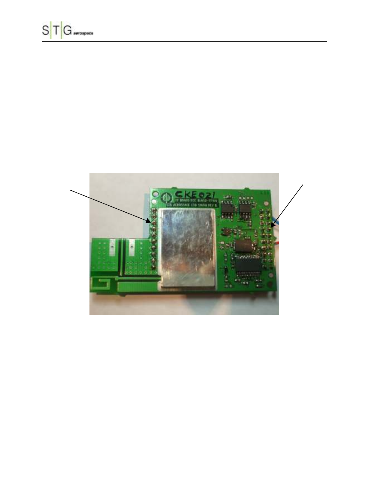
The S10011 transceiver is fixed to the host board using connectors JP1 and JP2. No other fixings are
used. Electrical connection to the host board is via the connector JP1. JP2 is used to programming the
S10011 EEPROM.
JP2
Commercial in Confidence
JP1
Figure 1. S10011 connections
3 Power Connection
The power supply to the S10011 unit is provided through connector JP1
The connections are as follows:
Pin 1 -ve and
Pin 12 +5.5 to +9V
S10011 Installation Guide Page 3 of 4 22/1/2007
Commercial in Confidence
Page 4

4 Siting
The effective radio range of the S10011 transceiver is not more than 100m in an indoor open space, and
so for good operation, each unit incorporating a transceiver should be in range of as many other units as
possible. The orientation of the unit is not critical, though best range results will be obtained between
units when the transceiver boards are in the same plane.
5 Labelling
Every unit containing the S10011 module must contain labeling on the outside of the unit stating
“Contains FCC ID Q52-TR100” In type no smaller than 8 point.
Commercial in Confidence
S10011 Installation Guide Page 4 of 4 22/1/2007
Commercial in Confidence
 Loading...