

Page 1
Sistemas de Filtrado y Tratamiento de Fluidos S.A.
Pol. Industrial La Armentera Parc. 86
22400 Monzón (Huesca) Tel. 974 401933 Fax. 974 417809
www.stf-filtros.com · e-mail: info@stf-filtros.com
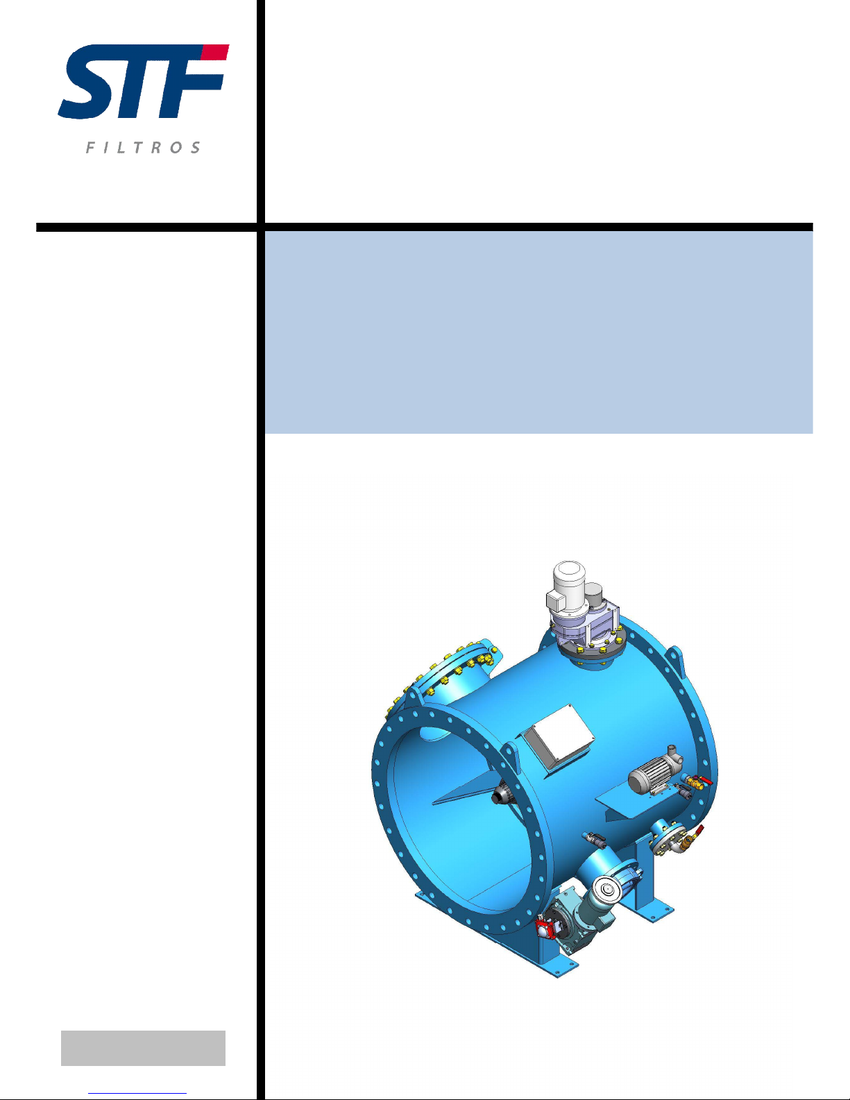
FMA – 6000
INSTALLATION, OPERATION AND
MAINTENANCE MANUAL
Ref: 6000/CPF/400/VM
Page 2

2
TABLE OF CONTENTS
INTRODUCTION....................................................................................................................3
SAFETY INSTRUCTIONS.....................................................................................................4
TECHNICAL SPECIFICATIONS...........................................................................................5
HEAD LOSS CHART…………………………………………………………………………….10
RECOMMENDED INSTALLATION DIMENSIONS AND DESIGN………………………….12
INSTALLATION AND START-UP INSTRUCTIONS...........................................................12
INSTALLATION DIAGRAM .................................................................................................14
MASTER PANEL PERFORMANCE....................................................................................14
PRESSURE DIFFERENTIAL REGULATION .....................................................................24
EXPLOSION DIAGRAM .....................................................................................................26
HYDRAULIC LAYOUT.........................................................................................................31
ELECTRIC PANEL ..............................................................................................................32
ELECTRIC LAYOUTS .........................................................................................................33
PREVENTIVE MAINTENANCE SCHEDULE......................................................................38
REFERENCES…………………...……………...……………………………………………….39
Page 3

3
INTRODUCTION
GENERAL
STF filtros congratulates you on the acquisition of the FMA 6000 self backwashing automatic filters.
This filter joins the STF filters wide range for agricullture, water treatment, sewage treatment plants and
other industrial use. All the products manufactured by STF-FILTROS are easy to install, use and maintain
and no special knowledge is required to operate them.
WARRANTY
The product has a two-year warranty from the moment of acquisition.
Follow this manual instructions to operate and maintain the filter.
Mechanical damages or any other damages caused by incorrect use are excluded from warranty.
The warranty gets also cancelled in case that no original spares are used.
Page 4

4
SAFETY INSTRUCTIONS
1. Prior to installation or filter operation, read carefully this manual.
2. Please note, the filters enters into a backflushing mode automatically, without prior warning.
3. Non authorized modifications or changes on the equipment are permitted.
4. Filter installation should be performed so as to avoid direct water splashing on the electrical
components.
5. Take correct precautions when raising and placing the equipment so that no damages are
produced.
6. Make sure to leave enough clearance so as to enable easy access for future treatments and safe
maintenance operations.
7. It is necessary to place a shut-off valve in the collector before the equipment to make the
maintenance easier.
8. Make sure that the equipment is operating at a correct working pressure.
9. Disconnect the filter from power supply before maintenance or treatment.
10. Never switch on the equipment without placing all the safety elements.
11. Don’t carry out a differente maintenance different from the indicated in this manual.
12. Use only original spare pieces.
Page 5

5
TECHNICAL SPECIFICATIONS
Equipment general description
The filter is composed of a metallic body, gear crown, main drain, opening valve (backwashing),
a pump for injecting clean water to the nozzles and a geared motor for rotation crown and measure and
control elements running. The filtering element is a special screen, fixed to the rotation crown, for filtering
all kinds of dirt particles, with a hydrodynamic profile that provides low head loss and reduces
turbulences, reduces head losses and avoid dirt particles accumulation.
All the materials are top-quality, in all the mechanic elements that are in contact with water it is
used stainless steel or similar. The filter body is made of carbon steel. The mechanic elements are in the
“clean water” side (water under the screen) in such a way that no foreign object can affect its performing
or deterioration.
FMA-6000 filters fit directly to the pipe by means of flanges, as it was one more element of the
pipe. Only the electric and control elements require installation.
It is a self backwashing automatic filter that has minimum maintenance and low consumption.
Performance
Water goes through the rotative screen and all the dirt particles bigger than the screen holes get
filtered. When the default pressure differential, backwashing starts, this is made area by area, collecting
waste materials to be expelled to the exterior.
The backwashing cycle starts when the default differential pressure is detected on both sides of
the screen. At that moment, the crown starts spinning until an area is placed just in the backwashing
chamber and then the backwashing valve is opened and the pump for water is started for water flooding
through the nozzles, from the “clean water” screen side. A screen exhaustive backwashing is obtained by
means of these nozzles. The backwashing valve stays open during the backwashing pre-set time and
then it closes. The crown moves on to the following area and the opening and closing the backwashing
valve and the water flooding pump cycle starts again.
Page 6

6
When the sector is placed in the backwash chamber, this remains watertight due to the nylon
bristles, for this reason, when the backwashing valve is opened, water flows through the filtration screen
in the opposite sense than the filtration process which means an important saving in backwashing water
consumption.
An electronic system protects mechanically the equipment. It is composed of an electronic torque
limiter, a progressive starting system and a crown position electronic control.
In the case that any foreign object blocks the screen rotation, the system inverts the rotation
alternatively until the foreign object is removed. In case it is too big, it will be extracted manually. An
alarm signal will turn on if any system failure occurs.
Performance
FIRST STARTING UP:
The pipe has to be object-free. The filter rotation has to be initiated before there is water flow in
the pipe.
COMMON PERFORMANCE:
When water flows through the filter, the dirt particles that are bigger than the filtration degree get
retained on the screen. These particles produce an increase on the differential pressure. If this differential
is not larger than 0.8 m.c.a, the filter backwashes according to the default time interval (8 hours,
variable). If the the scale 0.8 m.c.a. is not exceeded, the differential pressure system detects the same
one and the backwashing cycle starts.
Page 7

7
Maintenance
The FMA-6000 filter has only a mobile piece and it is accesible from outside. The rest of the
mobile pieces like engines and external valves are easily accesible. The rest of the maintenance is
based on visual inspections and greasing.
The necessary spare pieces change according to the dust quantity, sand and number of
backwashing cycles.
Screen technical characteristics
The “Double Diamond” screen is composed of quality AISI-316 electrowelded angle frames
arranged 90º between the longitudinal and the transversal angle frames. The particles retention angle
frames are rhombus-shaped so that water flow is possible (decrease head loss). This rhombus shape
makes screen backwashing easier by means of reducing backwashing time.
Backwashing cycle
Backwashing time cycle is 90 seconds, from which, during 54 seconds the backwashing valve is
open (including valve opening and closing time). For this reason, the backwashing consumption is quite
reduced (if the factory worker does not manipulate the default times).
Remove the thick particles from the crown
In case the filtering crown is blocked with any thick element, this will get unblocked automatically.
There is an electronic torque limiter in the system that detects when the crown is making more effort than
the effort that there is on the design, then the screen changes its spin direction (backwashing just in the
opposite direction).
If the crown gets blocked again, it will invert the spinning direction. If the blocking element could
not become detached from the filter after several spinning direction changes, then a manual intervention
would be carried out (opening the inlet and extracting manually the element that is stuck).
Head loss
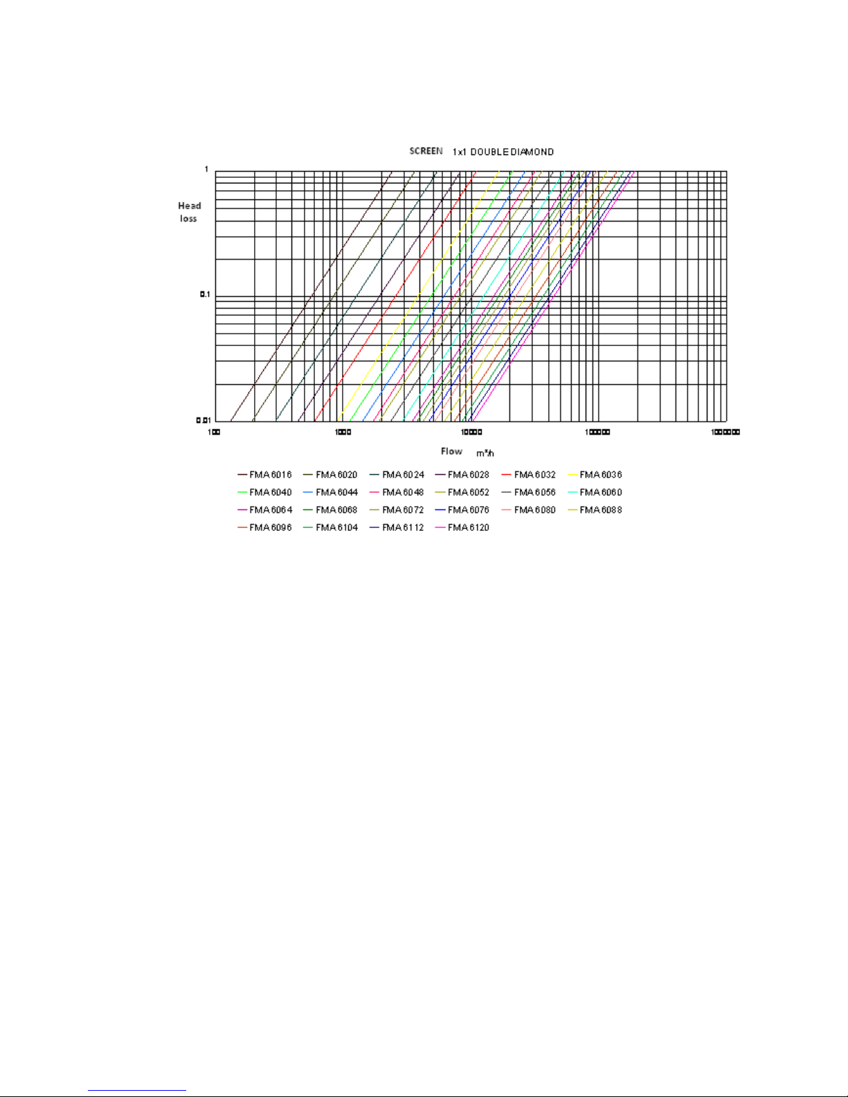
Head loss for nominal flow is 0,4 m.c.a. (head loss is made with clean water).
Page 8
8
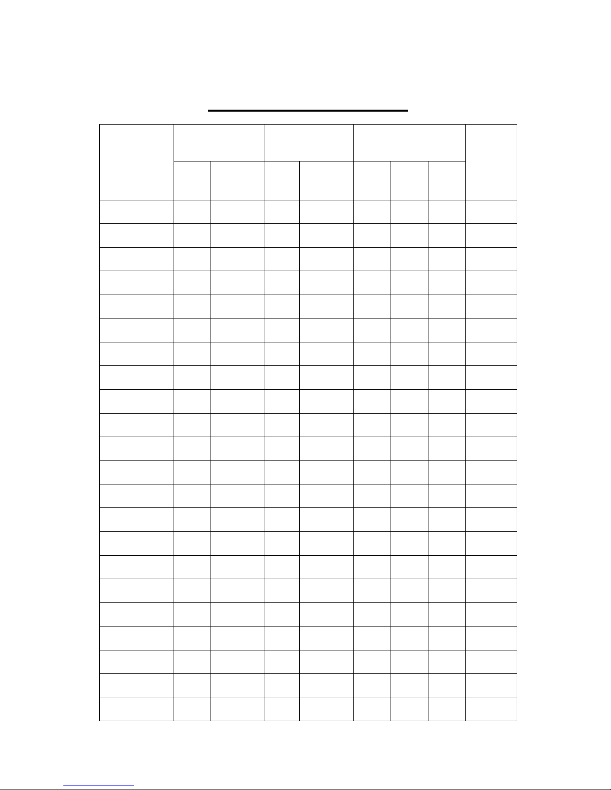
TECHNICAL SPECIFICATIONS
Connection inlet/
outlet
Drainage
connection
Nominal flow m3/s
Model
DN Inches DN Inches
Screen
1 x 1
Screen
1,5 x
1,5
Screen
2 x 2
Installed
power
capacity
FMA - 6016 400 16" 80 3" 0.089 0.13 0.17 1.48 Kw
FMA - 6020 500 20" 100 4" 0.13 0.19 0.36 1.48 Kw
FMA - 6024 600 24" 125 5" 0.2 0.3 0.56 1.68 Kw
FMA - 6028 700 28" 150 6" 0.31 0.45 0.65 1.75 Kw
FMA - 6032 800 32" 150 6" 0.43 0.63 0.92 1.83 Kw
FMA - 6036 900 36" 200 8" 0.61 0.89 1.25 2.1 Kw
FMA - 6040 1000 40" 200 8" 0.78 1.14 1.53 2.57 Kw
FMA - 6044 1100 44" 200 8" 0.97 1.42 1.75 2.8 Kw
FMA - 6048 1200 48" 250 10" 1.16 1.69 2.22 3.35 Kw
FMA - 6052 1300 52" 250 10" 1.3 1.9 2.5 3.5 Kw
FMA - 6056 1400 56" 300 12" 1.61 2,35 3.33 3.7 Kw
FMA - 6060 1500 60" 300 12" 1.95 2.85 3.89 4.1 Kw
FMA - 6064 1600 64" 300 12" 2.33 3.4 4.17 4.3 Kw
FMA - 6068 1700 68" 350 14" 2.57 3.75 4.72 4.7 Kw
FMA - 6072 1800 72" 350 14" 2.83 4.14 5.14 5.2 Kw
FMA - 6076 1900 76" 400 16" 3.25 4.75 5.56 5.5 Kw
FMA - 6080 2000 80" 400 16" 3.7 5.41 6.67 6 Kw
FMA - 6088 2200 88" 450 18" 4.42 6.45 7,78 6.2 Kw
FMA - 6096 2400 96" 500 20" 5.14 7.5 8.89 6.38 Kw
FMA - 6104 2600 104" 500 20" 5.75 8.39 11.1 6.72 Kw
FMA - 6112 2800 112" 500 20" 6.54 9.55 13.06 7.1 Kw
FMA - 6120 3000 120" 600 24" 7.1 10.3 14.44 7.25 Kw
Page 9
9
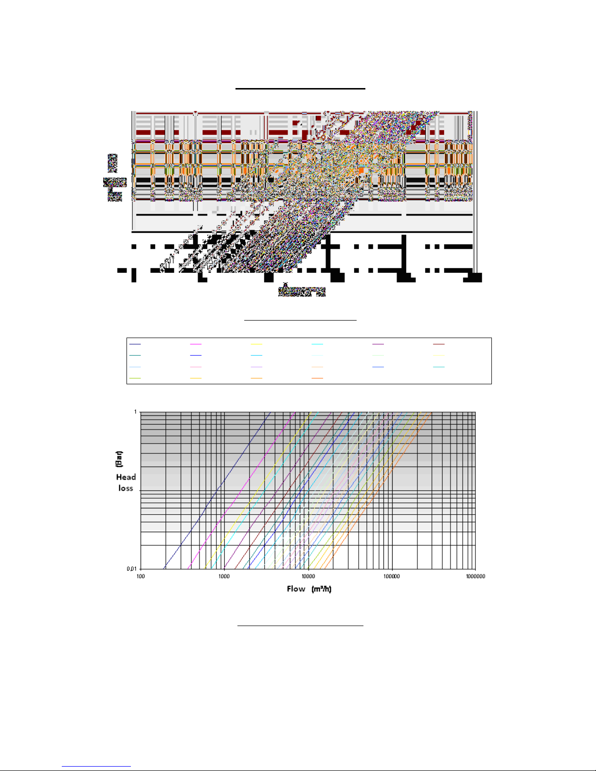
HEAD LOSS CHART
Screen 2 x 2 Double Diamond
Screen 1,5 x 1,5 Double Diamond
FMA - 6016 FMA - 6020 FMA - 6024 FMA - 6028 FMA - 6032 FMA - 6036
FMA - 6040 FMA - 6044 FMA - 6048 FMA - 6052 FMA - 6056 FMA - 6060
FMA - 6064 FMA - 6068 FMA - 6072 FMA - 6076 FMA - 6080 FMA - 6088
FMA - 6096 FMA - 6104 FMA - 6112 FMA - 6120
Page 10
10
Page 11
11
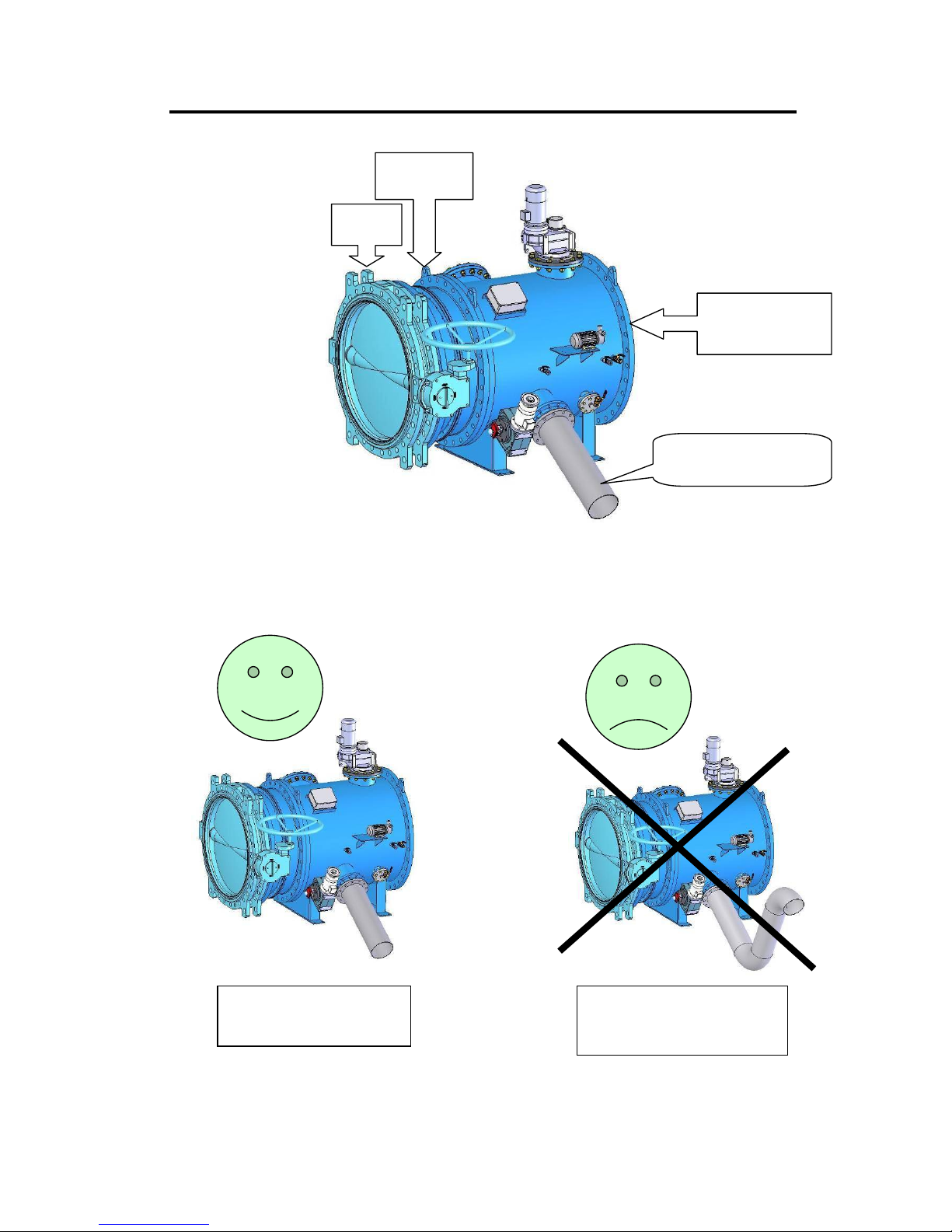
RECOMMENDED INSTALLATION DIMENSIONS AND DESIGN
It is advisable to assemble a motorized butterfly valve together with a dismantling joint, previous to the
filter. This is necessary in order to cut the water supply to the installation, in case of filter alarm or
preventive maintenance.
Shut-off
valve
Dismantling
joint
Filter
FMA
-
6000
Drain
pipe
Minimum 1% slope
CORRECT
1% slope downwards
INCORRECT
The pipe gets blocked up with
heavy solids.
Page 12

12
START-UP AND FIRST OPERATION
1. Make sure that water flood direction coincides with the arrows indicated on the equipment.
2. A backflow valve has to be installed if it is foreseen reflux in the filter in order to protect the
device from water hammer. STF is not responsible for any damages occurred on the
equipment, in case of water hammers or pressures superior to the maximum design
pressure.
3. Butterfly valves have to be placed in the filter inlet and outlet to drain off the pipe and carry out
the maintenance. (The outlet butterfly valve will depend on the equipment placement in the
installation).
4. Disconnect the equipment.
5. Turn the circuit breakers to ON.
6. The equipment is already adjusted to operate correctly, (0.8 m.c.a pressure differential; 8 hours
between safety backwashings).
7. The pipe has to be object-free. The filter rotation has to be started before there is water flow in
the pipe.
8. Backwash manually when filling in the installation, until the pipe is pressurized completely.
Page 13
13
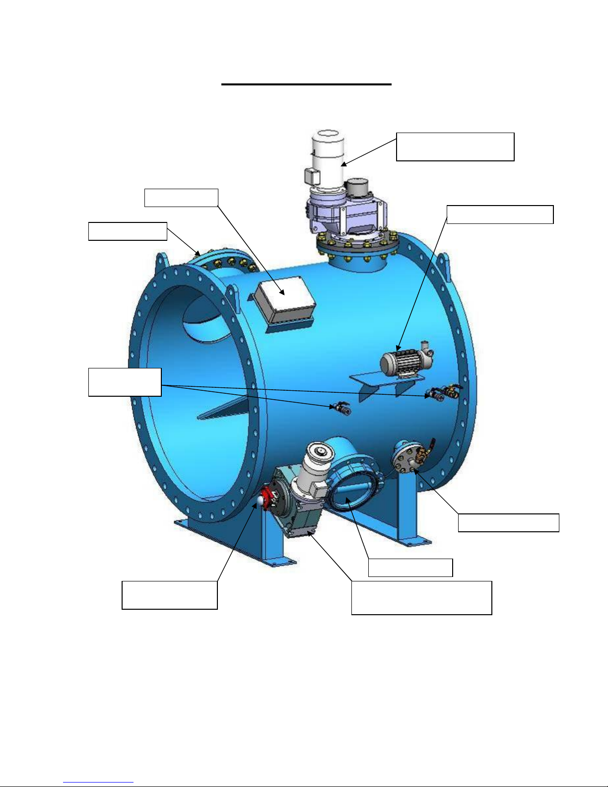
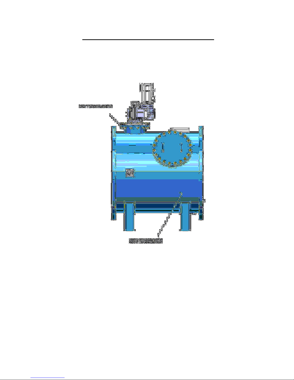
INSTALLATION DIAGRAM
Terminal block
Motorized reduction
gear
crown
Injection pump
Backwashing valve motorize
d
reduction gear
Backwashing valve
Limit switch
Backwashing valve
Injection manifold
Pressure
transducers
Man hole
Page 14
14
MASTER PANEL PERFORMANCE
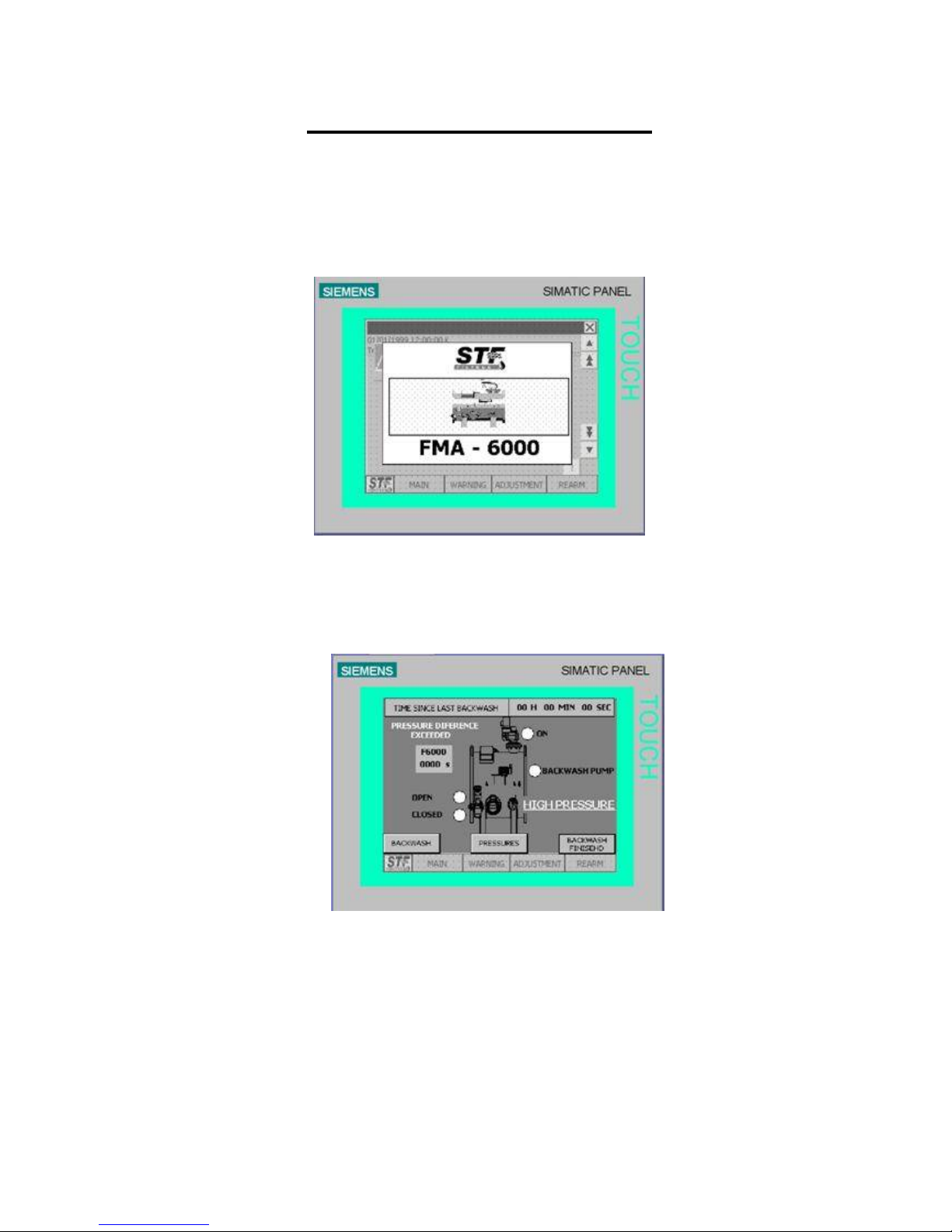
The control panel of the self backwashing FMA-6000 is controlled from a touch screen that allows you to
control and modify the equipment parameters.
STARTUP SCREEN (1)
Touch the STARTUP SCREEN to have access to the MAIN MENU screen.
MAIN MENU SCREEN(2)
On the main menu screen, time since the last backwashing filter appears on the screen besides the
backwashing time if its in the middle of the backwashing process.
The drain valve operation LEDS, the backwashing pump operation LEDS and the crown gear motor
during the backwashing process appear in the filter diagram.
When the default pressure difference on the PRESSURE screen (4) is reached, the legend “ EXCEEDED
Page 15
15
PRESSURE DIFFERENCE” will appear on the screen. Besides this, in case of pressure excess, the
legend “OVERPRESSURE” will be indicated.
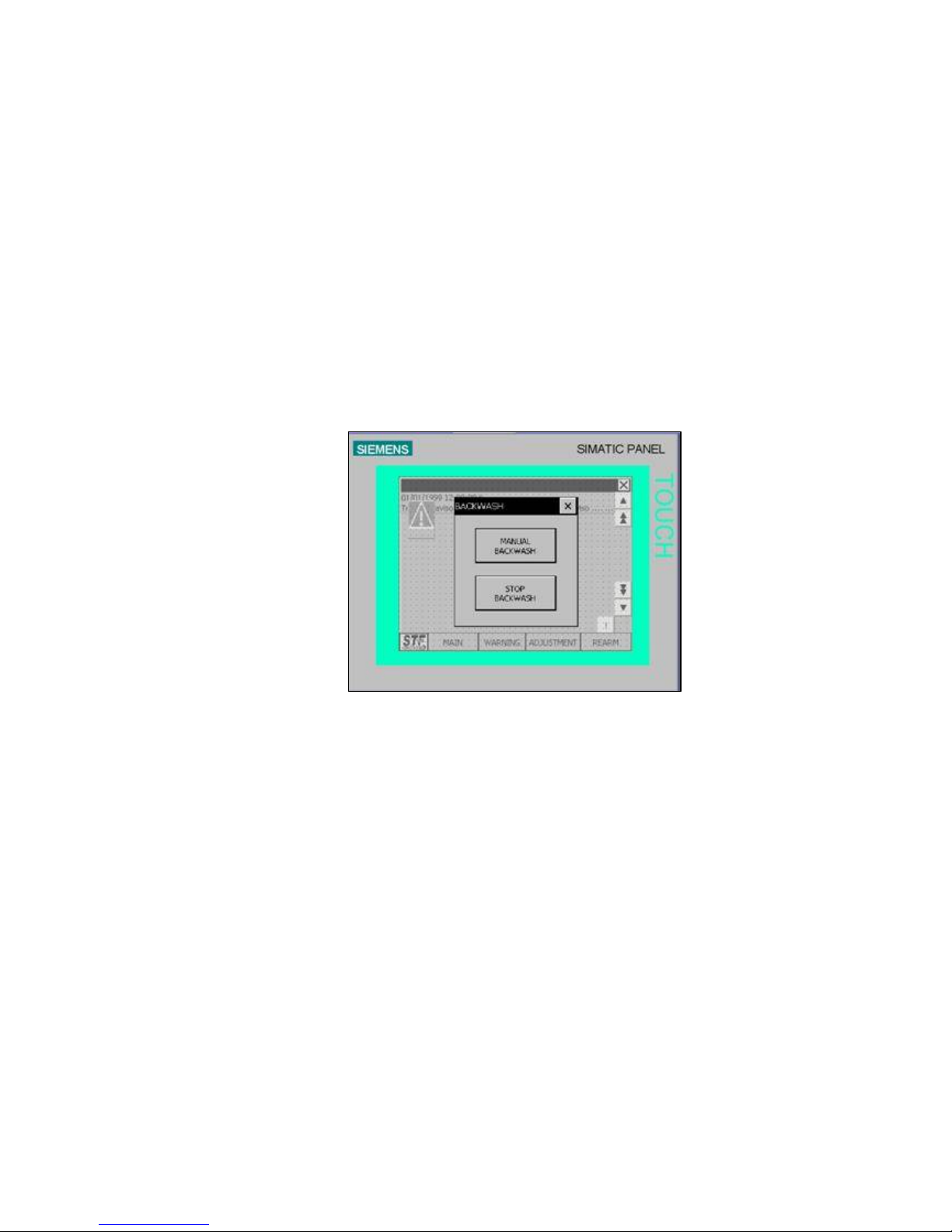
If an alarm goes on or there is an operation failure, a triangle warning symbol will appear on the screen.
MENUS ACCESS:
- INSTALLATION BACKWASHING(3): This screen allows you to start the backwashing
manually by pressing the STOP WASHING button, in this way the backwashing process
is stopped, the drain valve closes, the backwashing pump stops and the crown rotation
stops.
If you press X it returns to the previous screen (2).
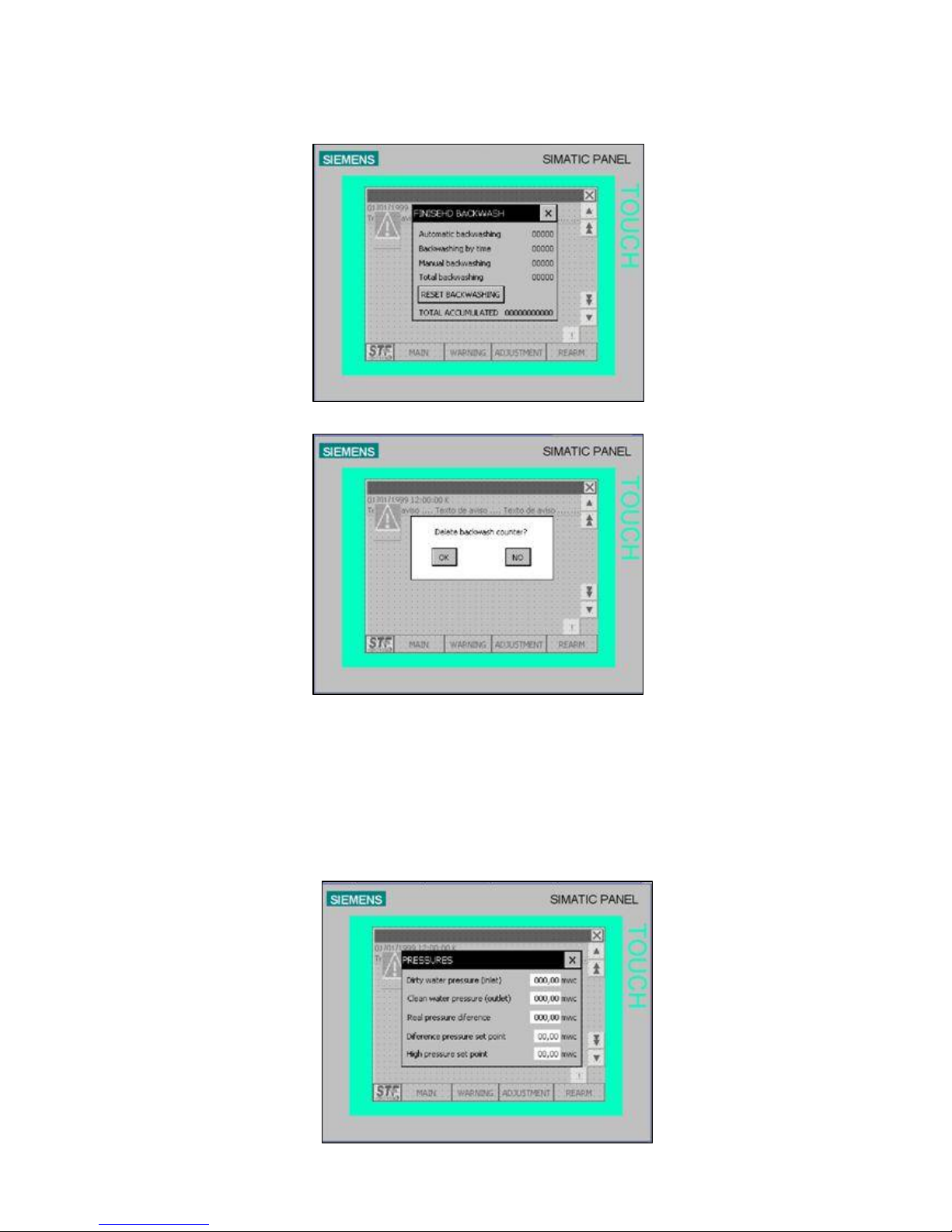
- BACKWASHINGS CARRIED OUT(4): This screen allows you to look up the
backwashings number that have been carried out in the equipment according to the
causes: If it has been manually (by means of the manual backwashing button),
automatically (because of pressure differential) or because of time. Besides this, the
total accumulated time is also indicated. Accumulated backwashings can not be deleted
and also the number of total backwashings that the equipment carries out between the
STF maintenance processes is indicated. Only STF personnel can turn this value to
zero.
If you press X it returns to the previous screen (2).
If you press BACKWASHINGS RESET the updating screen will appear.
Page 16
16
- PRESSURES (5): This screen allows you to look up both the inlet and the outlet
pressure. Besides the real time pressure differential in water column pressure. In the last
variable “set point pressure difference” it allows us to select to what pressure differential
we want to start a backwashing. The alarm value for overpressure is the value at which
the overpressure alarm will be indicated.
Page 17

17
The menu, which is common to all the screens, appears at the bottom of the screen. It this menu it is
possible to have access to:
WARNINGS screen (7)
ADJUSTMENTS screen (10)
REARM screen (11)
Page 18
18
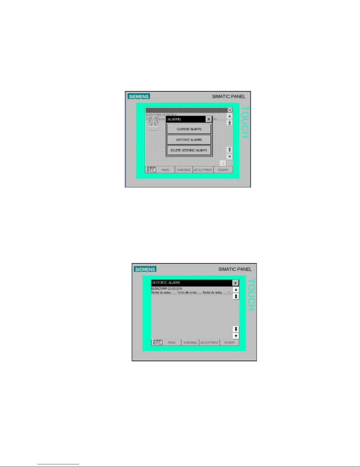
WARNINGS (7)
In the warnings menu, we can select the option to check the current alarms, to see the warnings record
since the the last updating and to delete the alarm record.
If you press X it returns to the previous screen .
The ALARMS screen indicates the actual warnings that are still to be corrected in the installation,
indicating the warning reason and the moment when they occurred.
The list is updated to check if the error has been corrected with the right inferior key. The blue triangle will
appear on the menu screen if there is an active warning.
Page 19
19
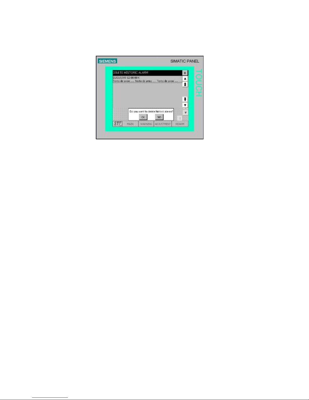
The alarms record screen indicates all the warnings that have appeared since the last deletion. If we
push DELETE THE ALARMS RECORD the option to delete all the no active warnings will appear.
When the programmer makes the consecutive backwashings indicated in the parameter
“CONSECUTIVE BACKWASHINGS ALARM” with no continuity, the safety device that stops the
backwashing will activate. The text (2) “ALARM” will appear on the screen in the inferior right hand side
and on the alarm screen. The legend: CONSECUTIVE BACKWASHINGS ALARM will appear.
This alarm indicates that the pressure switch sends a continuous signal to the electric panel, this can be
due to a pressure switch failure, to the fact that it has got blocked or to dust excess.
Unblock the pressure switch and press the REARM button to cancel the alarm.
Page 20
20
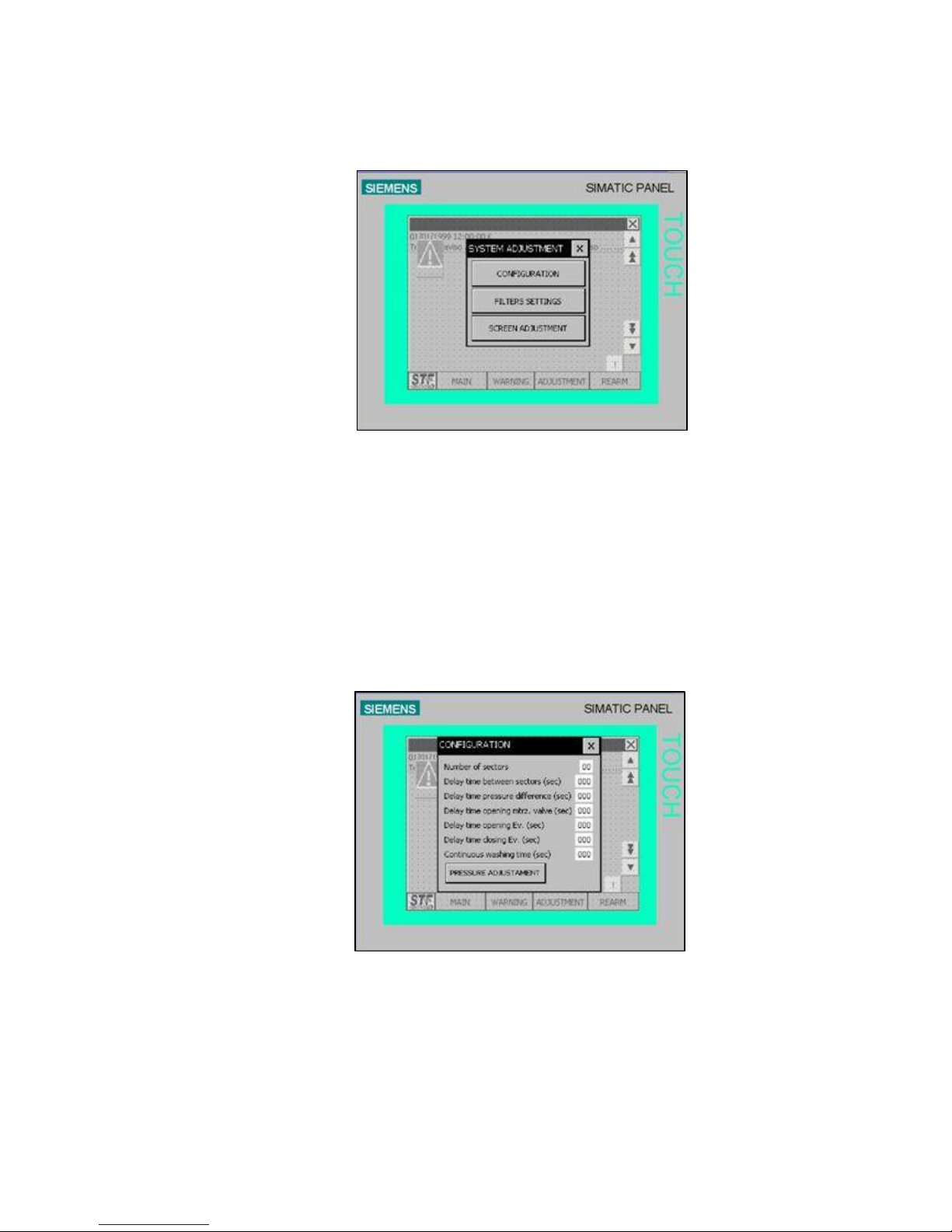
ADJUSTMENTS(10)
screen (10) allows you to configurate the installation parameters, the filter operating times and to adjust
the touch screen.
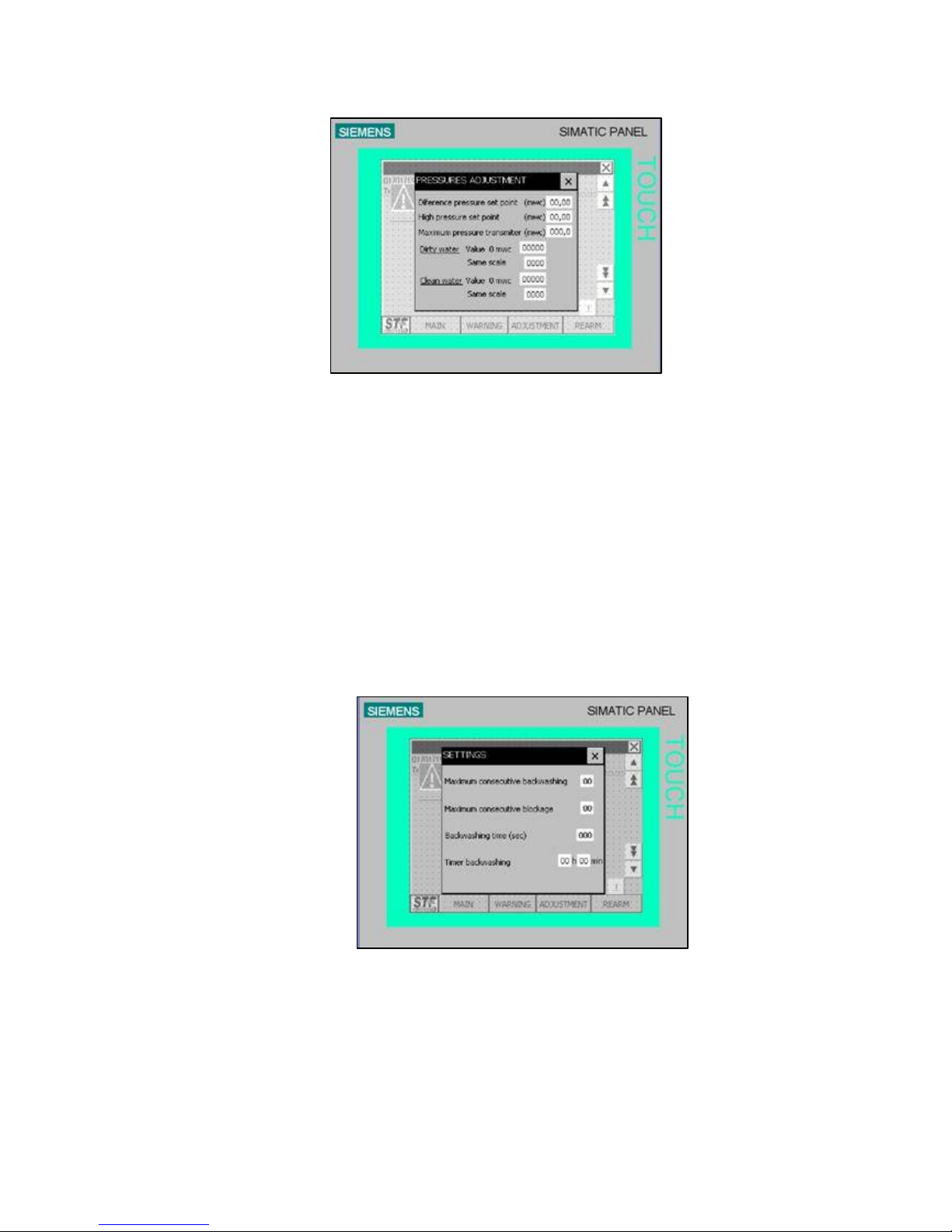
CONFIGURATION (11):
The CONFIGURATION screen allows you to adjust the backwashing process modifying several
parameters such as delay time, pressure difference to start backwashing, opening and closing the
backwashing collector butterfly as well as the continuous backwashing time.
Pressing the “PRESSURE ADJUSTMENTS” touch button it is possible to have access to the pressure
adjustments screen where the pressure parameters are modified.
Page 21
21
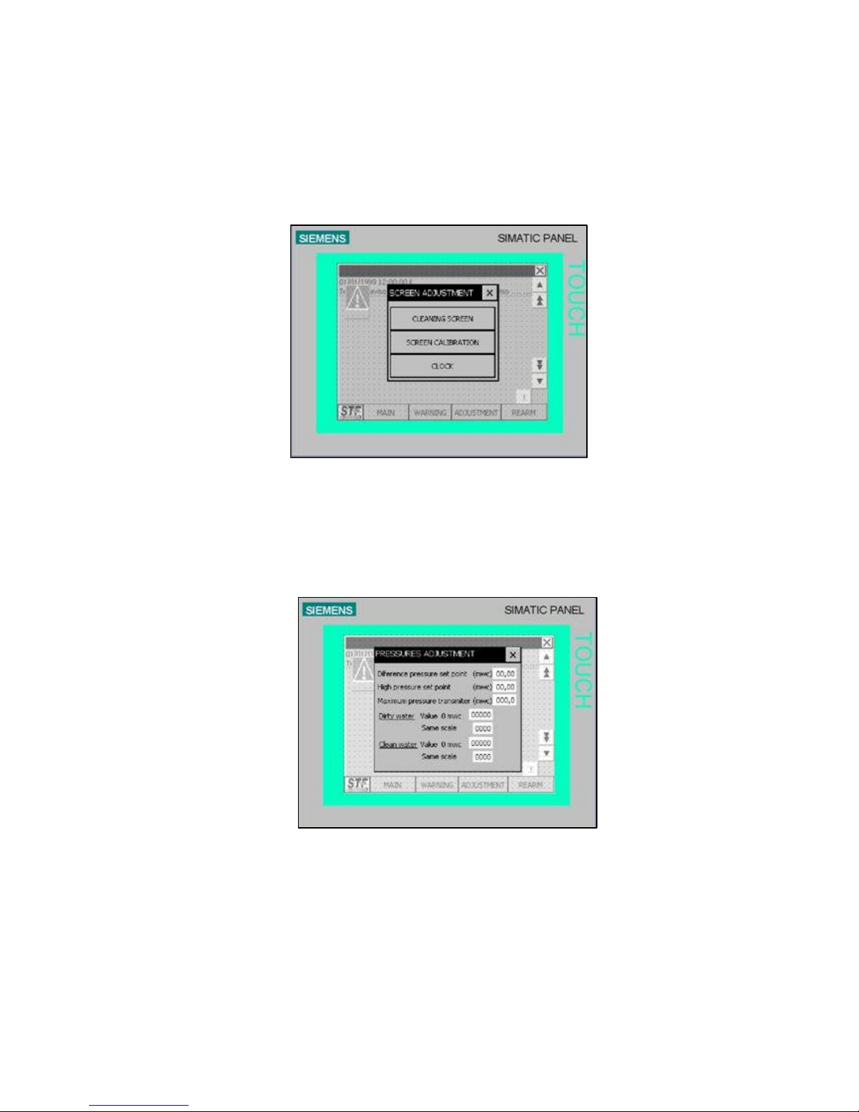
PARAMETERS (12):
The PARAMETERS screen allows you to modify the default values to control the backwashing process
and activate the alarms in case there is any failure. On this screen it is possible to modify the number of
consecutive backwashings, the number of consecutive blockages, the backwashing time and the time
between backwashings in case that the backwashing is not due to pressure difference.
Page 22
22
SCREEN ADJUSTMENTS (13):
The ADJUSTMENTS SCREEN allows you to have access to the previously mentioned screens
(backwashings carried out (5)), as well as to set the screen sensibility (14) or to set date and time (15).
TOUCH SETTING (14): It is possible to adjust the pressure values to make a filtering process more
effective on the touch setting screen.
Page 23

23
WATCH (15):
IMPORTANT:
WHEN THE FILTER TRIGGERS THE ALARM SIGNAL, THIS MUST BE CARRIED OUT IMMEDIATELY TO
STOP WATER FLOODING THROUGH THE FILTER BY CLOSING THE BUTTERFLY VALVE BEFORE THE
FILTER.
Page 24
24
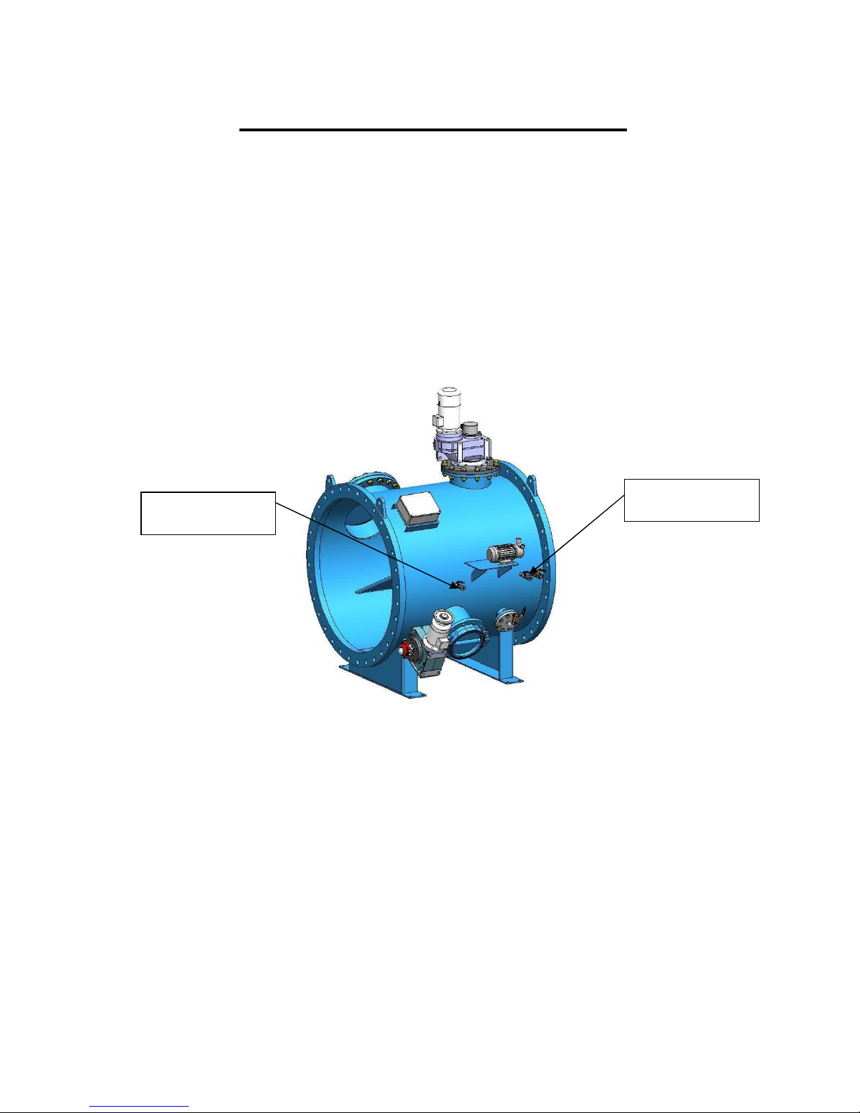
PRESSURE DIFFERENTIAL REGULATION
The pressure differential regulation is made in an electronic way by means of pressure
transducers 4 - 20mA located in the inlet and the outlet. These transducers give a stable and precise
signal of pressure in both filter chambers and the electric panel calculates the pressure differential.
The pressure differential is regulated to 0.8 m.c.a and it can only be changed by STF-Filtros
technical skilled personnel.
Pressure transducer
INLET
Pressure transducer
OUTLET
Page 25
25
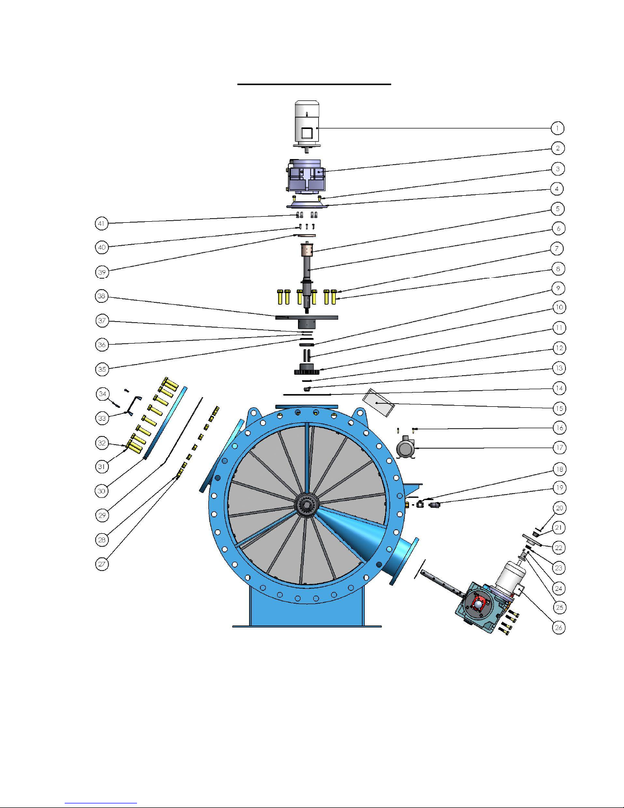
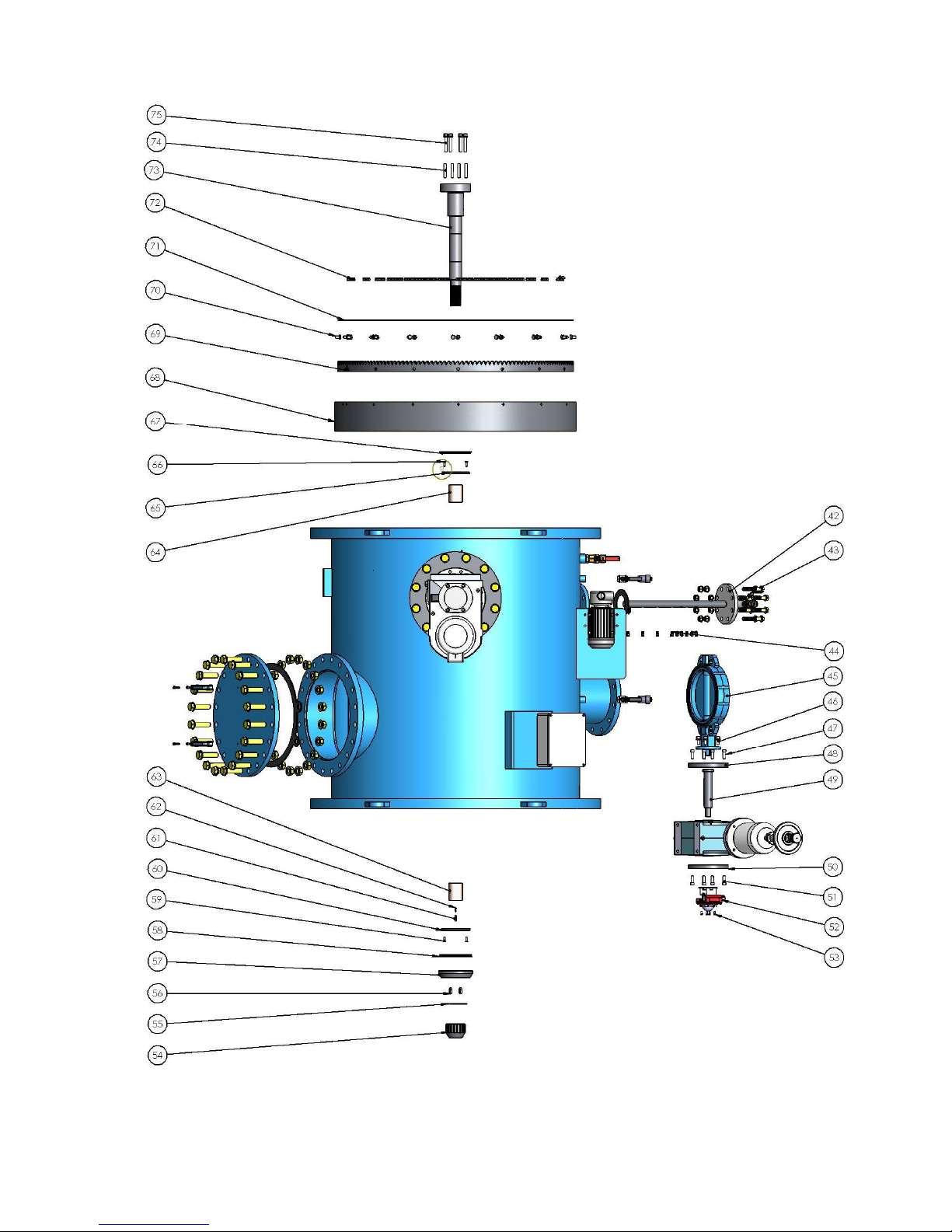
EXPLOSION DIAGRAM
Page 26
26
Page 27

27
POSITION DESCRIPTION CODE
1 Crown motor
2 Crown reducer
3 Outlet flange scew
4 Outlet flange
5 Crown gear motor guide bush
6 Drive shaft
7 Washer
8 Screw
9 Rectified washer
10 Pinion machine key
11 Pinion
12 Pinion washer
13 Pinion nut
14 O-ring joint
15 Electrical Junction Box
16 Pump screw
17 Injection pump
18 Needle valve
19 Pressure transducer
20 Clutch washer
21 Clutch bush
22 Clutch wheel
23 Clutch spring
24 Clutch cylindrical dowel pin
25 Gear motor clutch connection
26 Backwashing valve gear motor
27 Man hole nut
28 Man hole washer
29 Man hole flat joint
30 Man hole blind flange
31 Man hole washer
32 Man hole screw
33 Handle
34 Handle screw
35 Crown gear motor VA joint
36 Crown gear motor quadric joint
37 Crown gear motor o-ring
38 Crown gear motor flange
39 Flap
Page 28
28
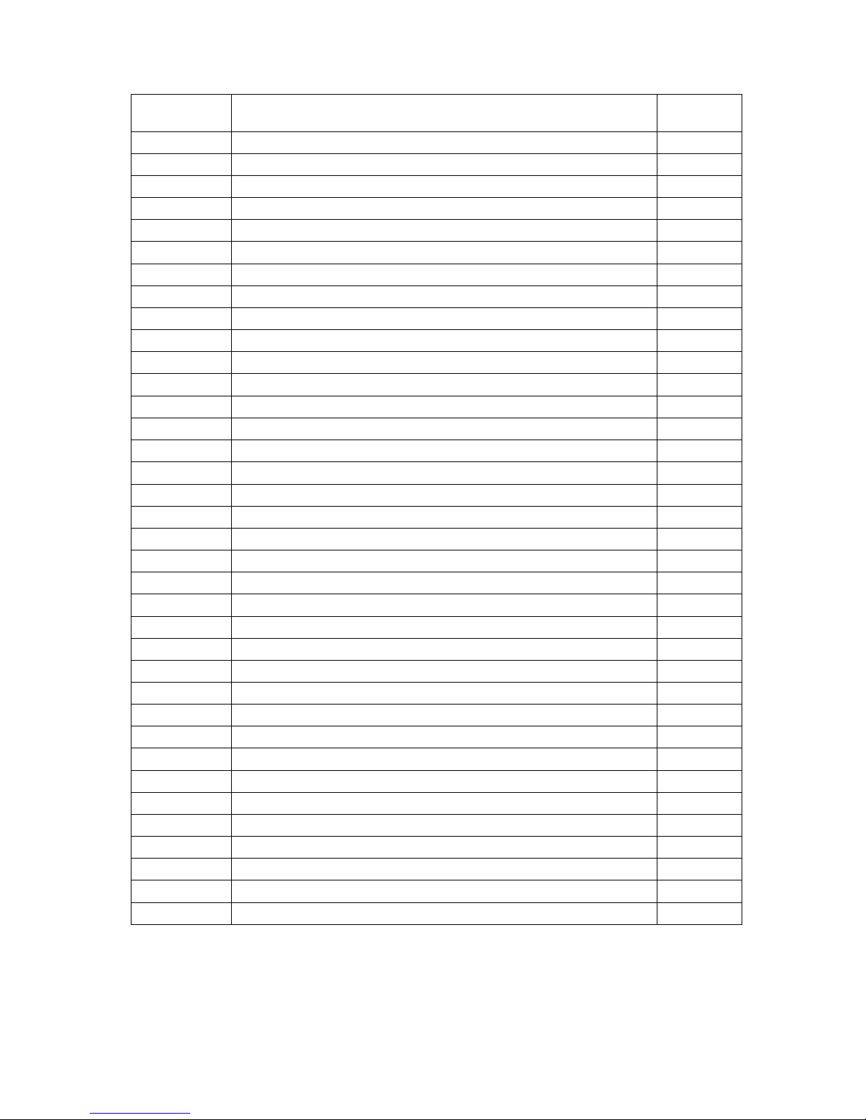
POSITION DESCRIPTION CODE
40 Crown gear motor flap screw
41 Gear motor outlet flange screw
42 Nozzles distribution manifold
43 Nozzles manifold screw
44 Nozzles
45 Backwashing valve
46 Connection flange screw
47 Gear motor connection flange screw
48 Connection flange
49 Butterfly valve drive shaft
50 Butterfly valve limit switch flange
51 Limit switch flange screw
52 Limit switch
53 Limit switch screw
54 Crown main nut
55 Crown shaft primary washer
56 Crown shaft machine key
57 Crown shaft secondary washer
58 Crown shaft VA joint
59 Axial busher screw
60 Axial washer
61 Screw
62 Spring screw
63 Crown shaft guide bush
64 Crown shaft guide bush
65 Axial washer
66 Axial washer screw
67 Crown shaft VA joint
68 Crown
69 Gearwheel
70 Gearwheel screw
71 Filtering screen
72 Filtration screen screw
73 Crown main shaft
74 Main shaft dowel pins
75 Crown shaft screw
Page 29
29
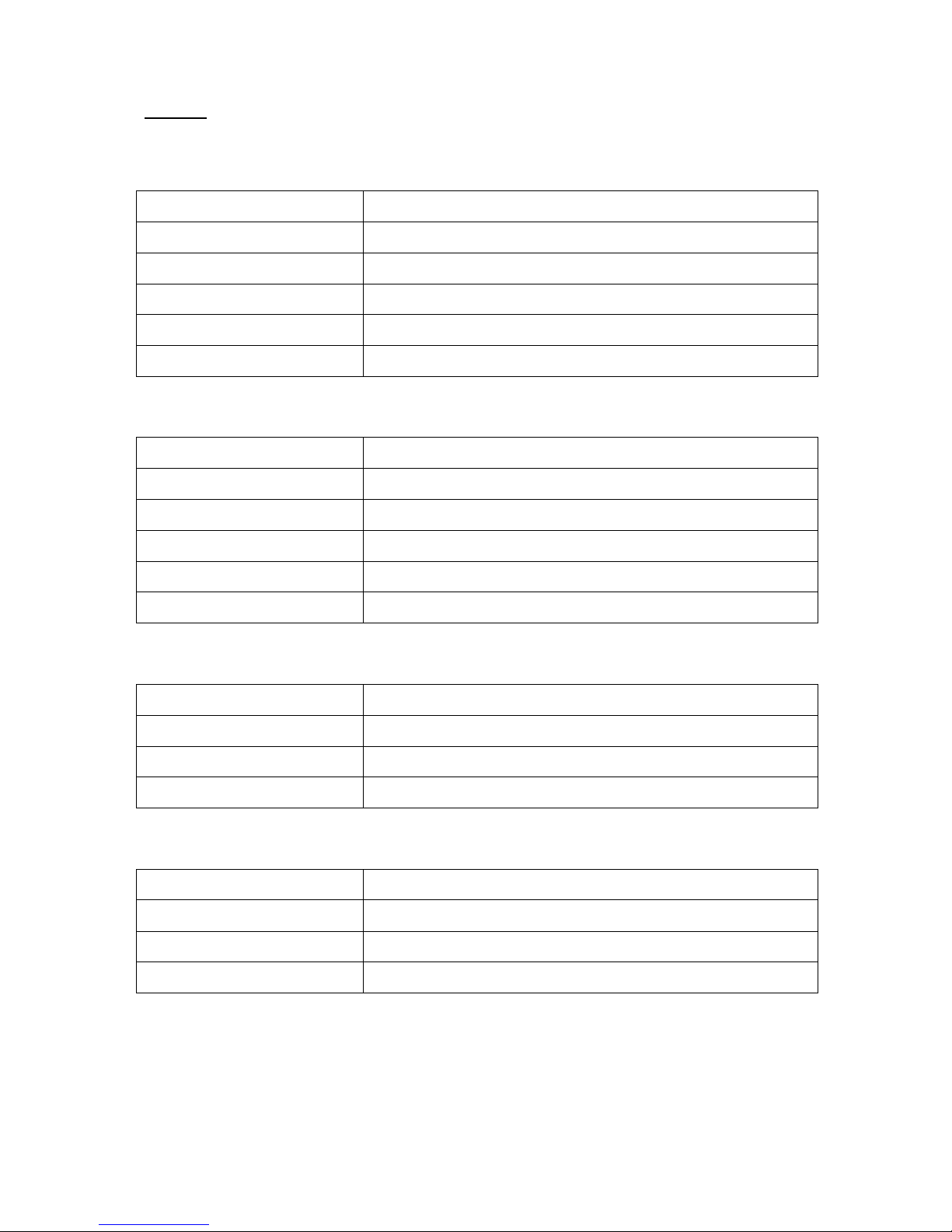
Materials
THE FILTER BODY
Body Carbon steel S-235-JR
Suction ajutage Stainless steel AISI-304
Structural rings Stainless steel AISI-304
Flanges support Stainless steel AISI-304
Internal protection Epoxi alimentario
External paint Epoxi-polyester
FILTERING CROWN
Structure Stainless steel AISI-304
Screen panels Stainless steel AISI-304
Shaft Stainless steel AISI-304
Hub bearing Stainless steel AISI-304
Machinery Stainless steel AISI-304
Supports Stainless steel AISI-304
TRACTION MECHANISM
Frame Stainless steel AISI-304
Driving shaft Stainless steel AISI-304
Bearing Aluminium bronze
Pinion Stainless steel AISI-304
BACKWASHING VALVE
Body Epoxi ductile iron
Disk Epoxi ductile iron
Coating EPDM
Shaft Stainless steel AISI-304
Page 30
30
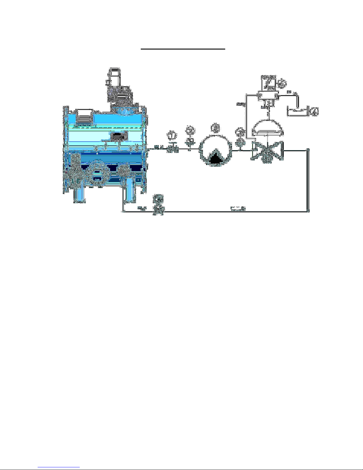
HYDRAULIC LAYOUT
1- Ball valve
2- Pressure gauge
3- Pressurization pump
4- Hydraulic valve
5- Solenoid
6- Drainage
Page 31
31
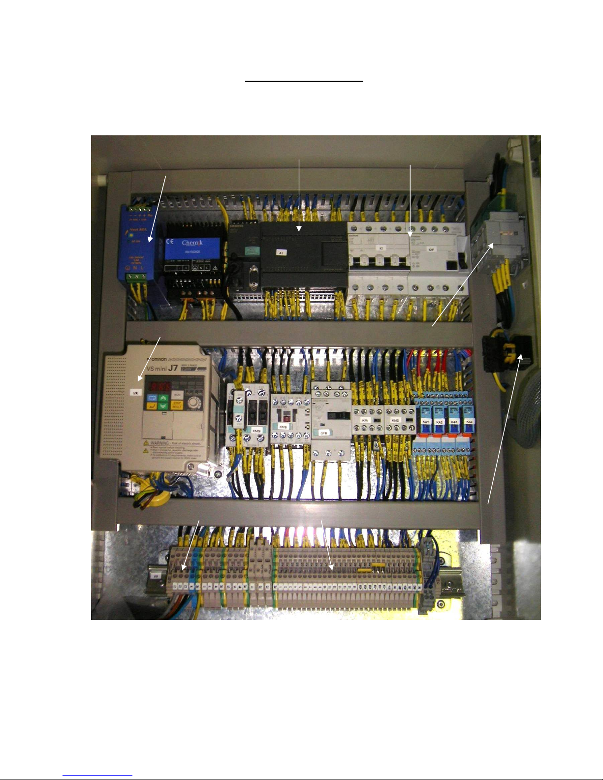
ELECTRIC PANEL
PLC SIEMENS S7-200
POWER SUPPLY UNIT
220V AC724 V DC
FREQUENCY VARIATOR
PIA
AND
GROUND
FAULT BREAKER
MASTER SWITCH
EMERGENCY BUTTON SUPPLY 400 V AC 3 Ph FILTER CONNECTIONS
Page 32
32
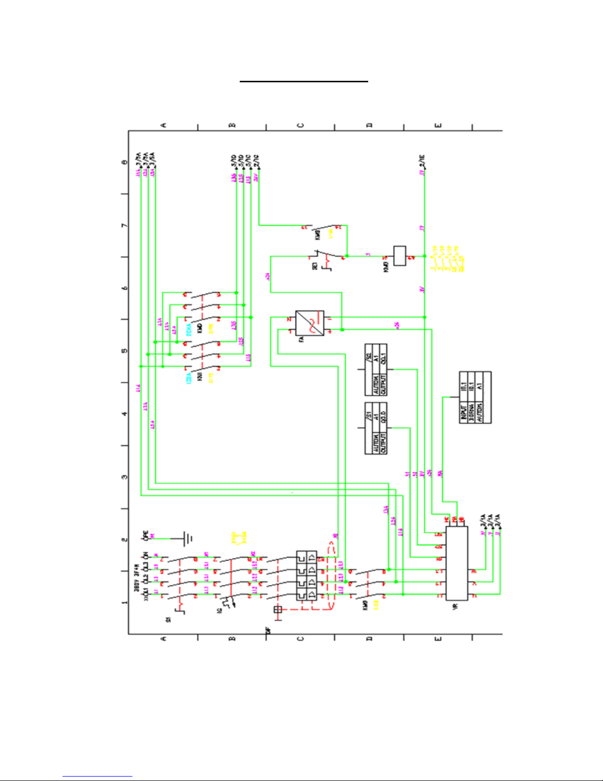
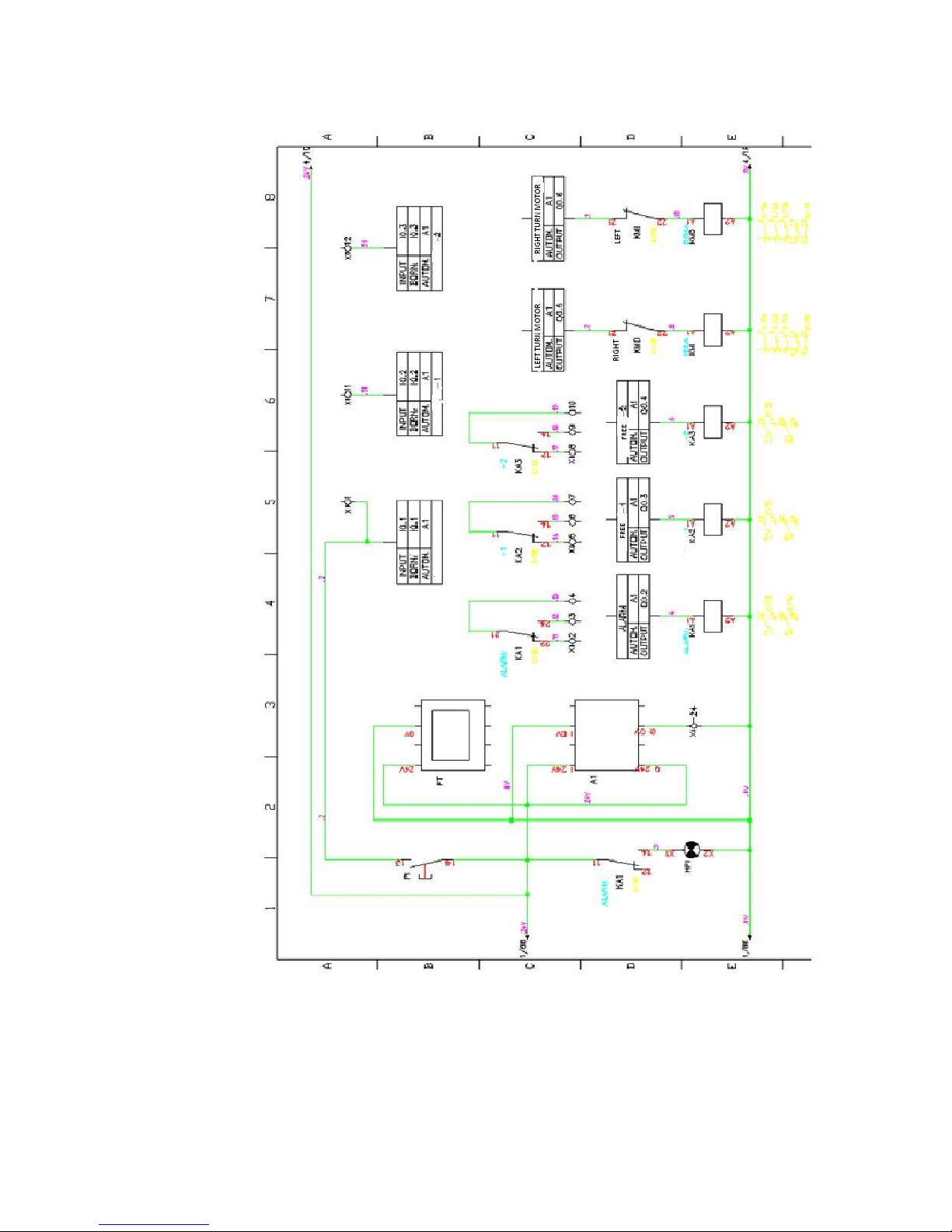
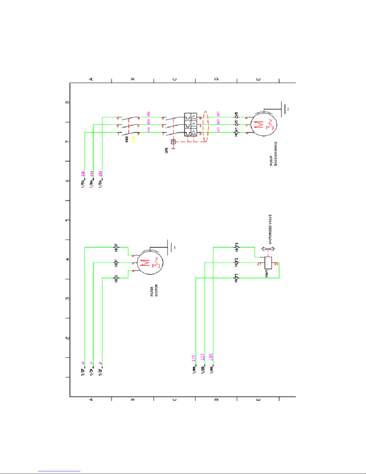
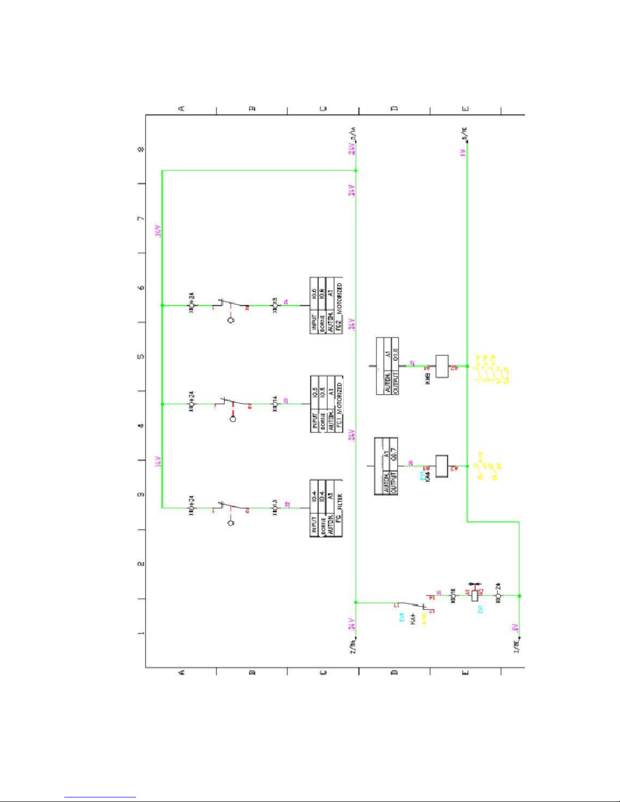
ELECTRIC LAYOUT
Page 33
33
Page 34
34
Page 35
35
Page 36
36
PREVENTIVE MAINTENANCE SCHEDULE
Grease the indicated pieces every 3 months.
If a long stop is planned, backwash once a week so that all the mechanisms get lubricated.
It is not necessary to make any other maintenance, gearmotors have enough oil for its useful life.
FMA-6000 filter has a mobile piece and it is accessible from outside. The rest of the mobile pieces such
as engines and valves are external and easily accessible. The rest of the maintenance is based on visual
inspections and greasing.
Page 37
37
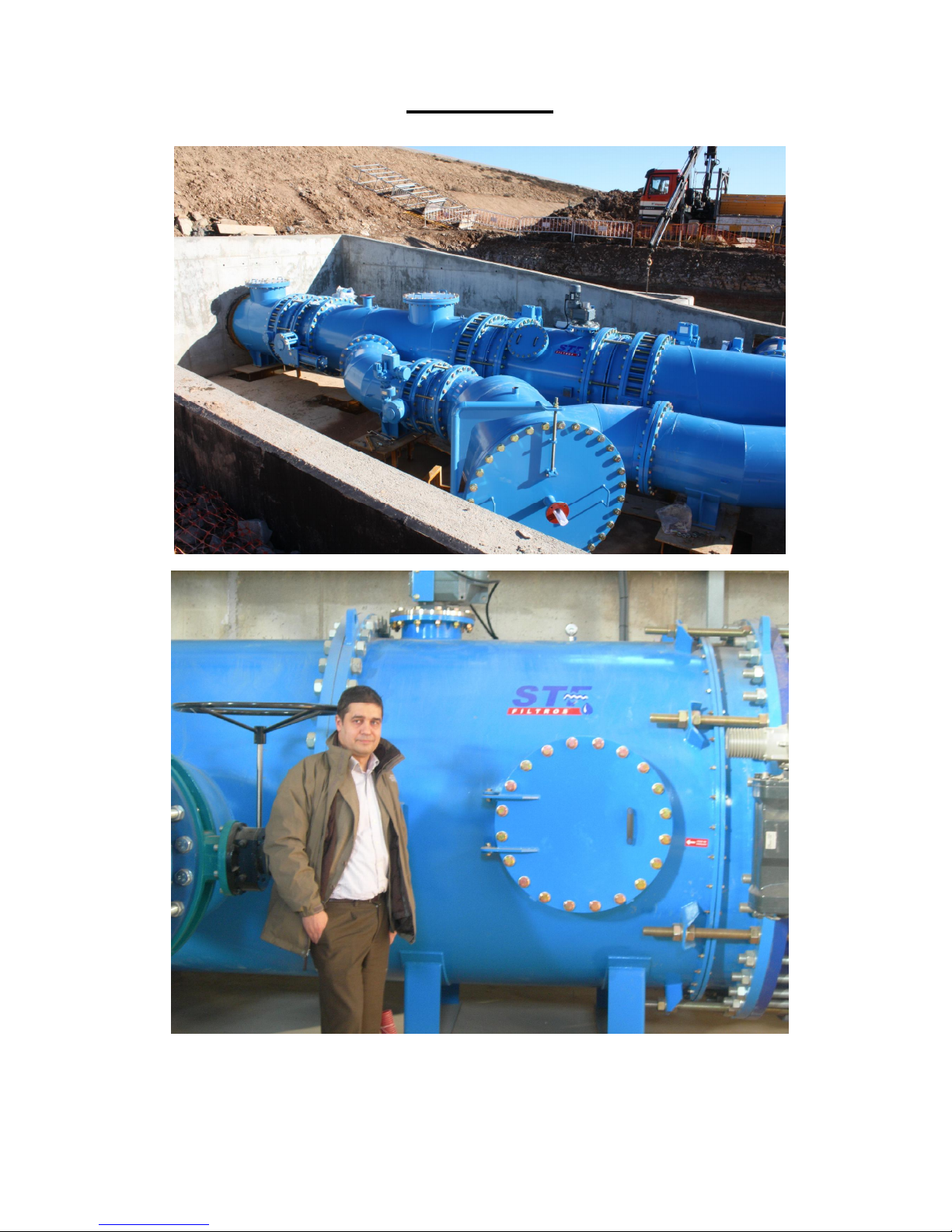
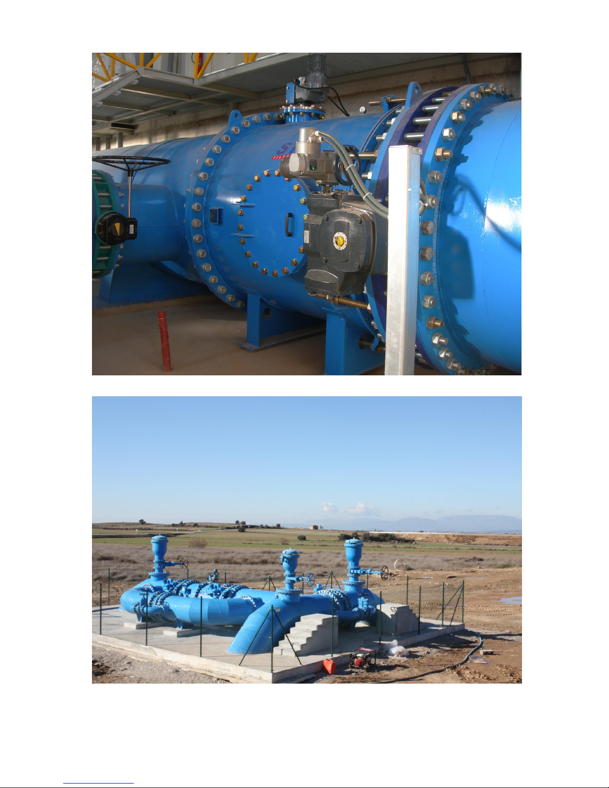
REFERENCES
Page 38
38
Page 39
39
Page 40
40
 Loading...