

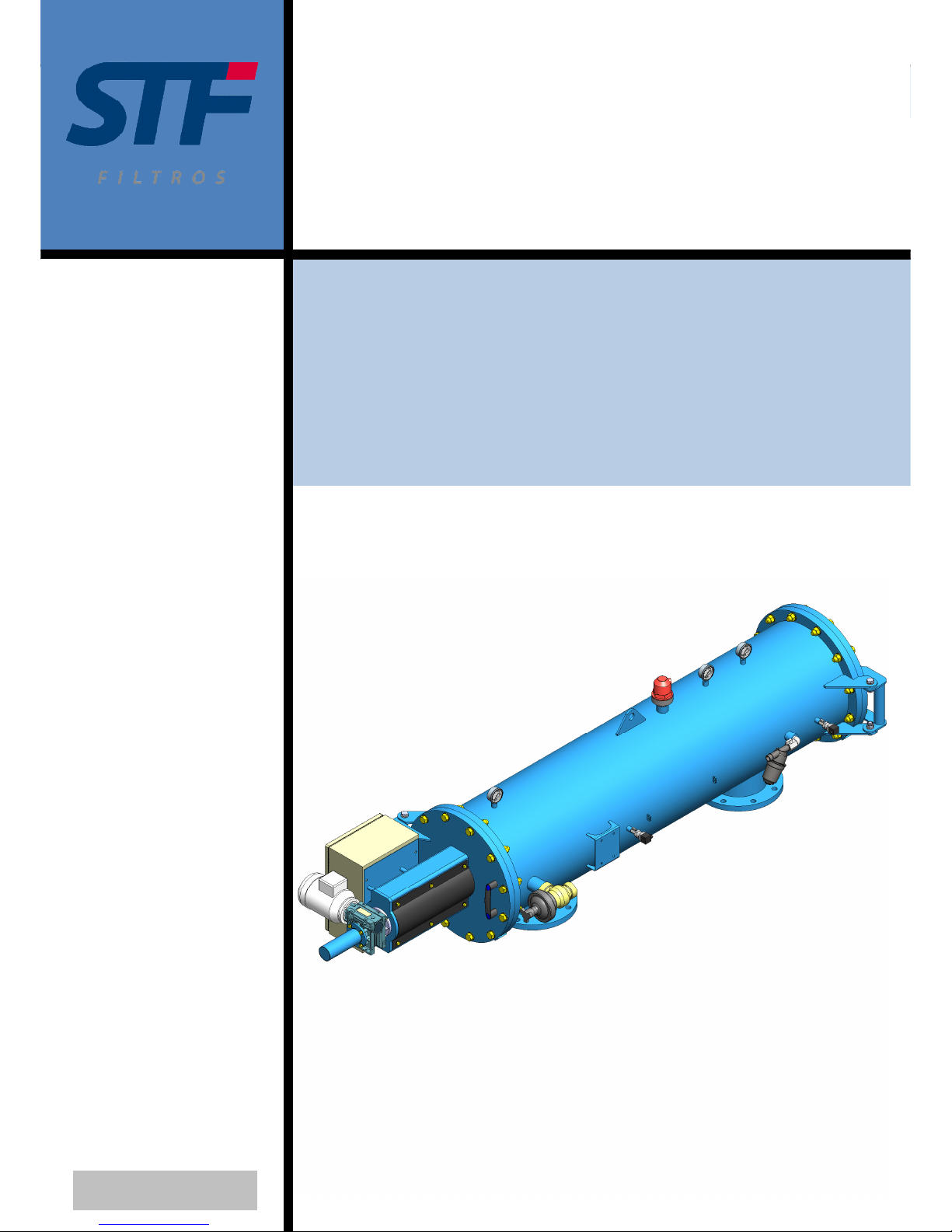
STF-Filtros FMA-2000 series, FMA-2008, FMA-2003, FMA-2004, FMA-2010 Installation, Operation And Maintenance Manual
...Page 1
Installation, operation and maintenance manual - FMA 2000
Ref: 2000/CPF01/230/VH 1
FMA – 2000
INSTALLATION, OPERATION AND
MAINTENANCE MANUAL
Ref: 2000/CPF01/230/VH
Page 2

Installation, operation and maintenance manual - FMA 2000
Ref: 2000/CPF01/230/VH 2
TABLE OF CONTENTS:
1. – INTRODUCTION ....................................................................................................... 6
2. – WARRANTY ............................................................................................................. 7
3. – SAFETY ................................................................................................................... 8
4. –FMA-2000 FILTER DESCRIPTION ............................................................................. 10
5. – FMA-2000 PERFORMANCE ..................................................................................... 11
6. – TECHNICAL CHARACTERISTICS ............................................................................. 12
7. – IDENTIFICATION PLATE ......................................................................................... 16
7. – IDENTIFICATION PLATE ......................................................................................... 17
8. – INSTALLATION INSTRUCTIONS .............................................................................. 18
9. – STARTING INSTRUCTIONS. .................................................................................... 19
10. – MAINTENANCE INSTRUCTIONS. ........................................................................... 21
11. – PREVENTIVE MAINTENANCE SCHEDULE .............................................................. 22
12. – CONTROL PANEL ................................................................................................. 23
12.1. – CONNECTION .................................................................................................... 25
12.2. – PERFORMANCE ................................................................................................ 27
12.3. –MODIFYING PARAMETERS ................................................................................. 28
13. – WARNINGS AND ALARMS ..................................................................................... 32
14. – ELECTRIC DIAGRAM ............................................................................................ 33
15. – HYDRAULIC CIRCUIT. ........................................................................................... 35
16. – EXPLOSION DRAWING ......................................................................................... 37
17. – ERROR DETECTION ............................................................................................. 45
Page 3
Installation, operation and maintenance manual - FMA 2000
Ref: 2000/CPF01/230/VH 3
This device has been manufactured in such a way that its performance does not bring about any
risks for the designed usage, provided that:
Both the installation and the management, as well as the maintenance have to be carried out
according to the manual instructions.
The facilities conditions and the supply voltage have to follow the specified instructions.
Any different usage from this will be incorrect, as well as the non authorized modifications made
by the manufacturer. The damages occurred because of an incorrect usage will be the user
responsibility what will automatically determine the warranty cancellation.
Remember that the device will contain electric components with voltage, and therefore, all the
service operations or maintenance will be performed by qualified and skilled personnel, aware of
the necessary precautions. Before having access to the interior parts, the electric supply has to
be dismantled.
READ AND KEEP THESE INSTRUCTIONS
We really want you to save time and money!
We assure that this entire manual reading will guarantee the correct installation and a safe
product usage.
.
IMPORTANT WARNINGS
READ CAREFULLY AND FOLLOW THE DEVICE MANUAL
INSTRUCTIONS. THE MANUFACTURER IS NOT RESPONSIBLE FOR THE
DAMAGES OCCURED OR THE NEGLIGENCES HAPPENED AS A
RESULT OF NOT READING THE MANUAL
Page 4
Installation, operation and maintenance manual - FMA 2000
Ref: 2000/CPF01/230/VH 4
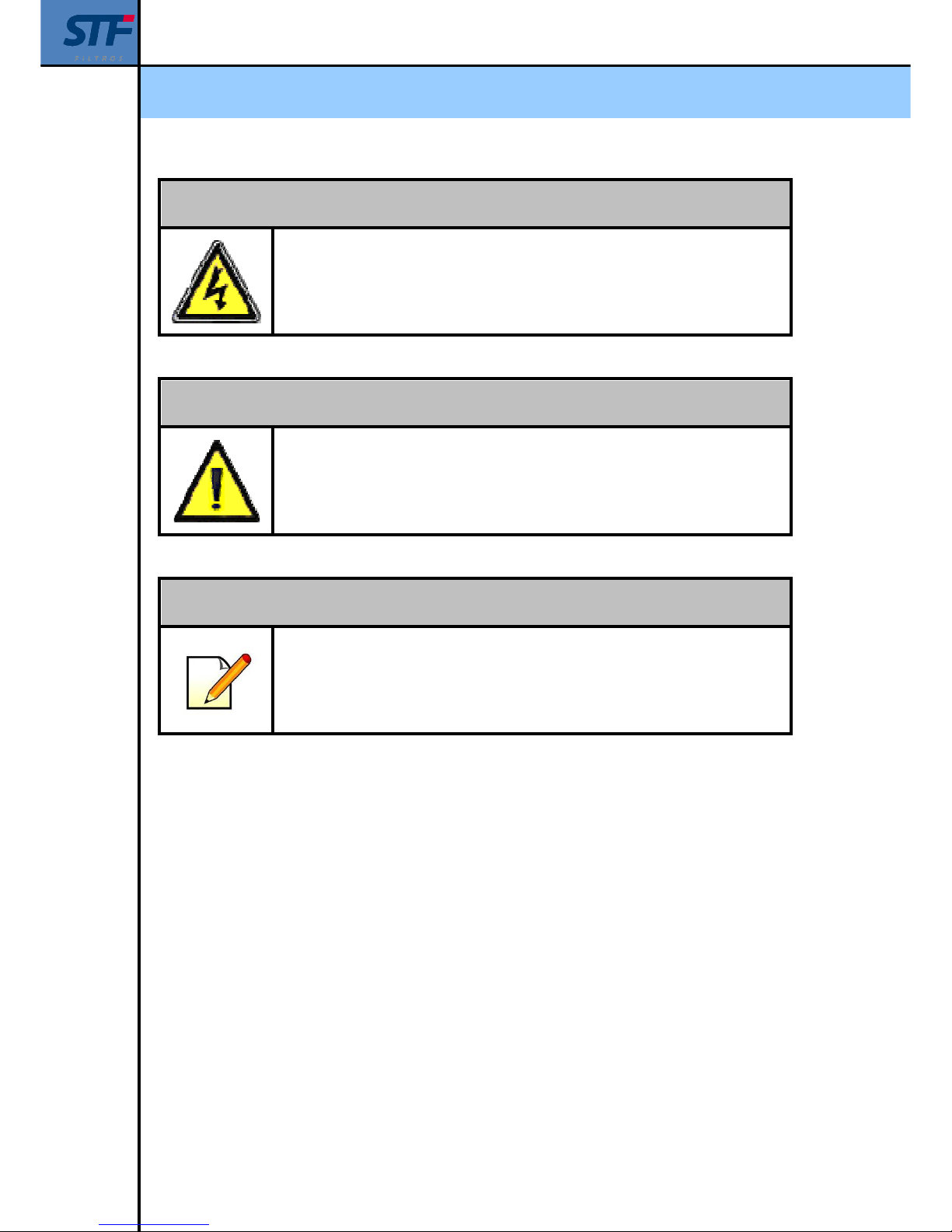
BEWARE!
ELECTRICAL DISCHARGE RISK. THE OPERATIONS INDICATED WITH
THIS SYMBOL WILL HAVE TO BE PERFORMED ONLY BY SKILLED
TECHNICAL PERSONNEL
BEWARE!
ESSENTIAL INFORMATION AND ASPECTS.
HAVE THE DEVICE DOCUMENTATION AS A REFERENCE.
NOTE
REALLY IMPORTANT INFORMATION AND ASPECTS.
Page 5
Installation, operation and maintenance manual - FMA 2000
Ref: 2000/CPF01/230/VH 5
Page 6
Installation, operation and maintenance manual - FMA 2000
Ref: 2000/CPF01/230/VH 6
1. – INTRODUCTION
STF – FILTROS congratulates you on the acquisition of the FMA – 2000 self backwashing
automatic filters.
All the products manufactured by STF – FILTROS are easy to install, use and maintain.
If you have any doubts about its performance after reading this manual, please contact the STF-
Filtros Technical Department.
CONTACT
SISTEMA DE FILTRADO Y TRATAMIENTO DE FLUIDOS S.A
+34 974 401 933
+34 974 417 809
www.stf-filtros.com
Page 7
Installation, operation and maintenance manual - FMA 2000
Ref: 2000/CPF01/230/VH 7
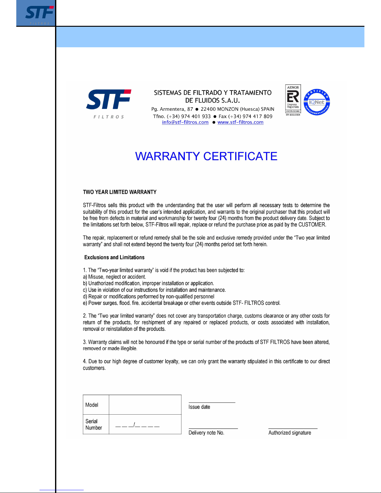
2. – WARRANTY
Page 8
Installation, operation and maintenance manual - FMA 2000
Ref: 2000/CPF01/230/VH 8
3. – SAFETY
FILTER SAFE USE INSTRUCTIONS
THE INCORRECT USE AND MAINTENANCE OF THE EQUIPMENT MAY
CAUSE PHYSICAL INJURIES.
IT IS STRONGLY RECOMMENDED TO RESPECT THE FOLLOWING
INSTRUCTIONS IN ORDER TO AVOID RISKS.
USE ACCIDENT PREVENTION MEASURES THAT GUARANTEE YOUR
SAFETY AND THE EQUIPMENT SAFETY.
Do not touch parts in motion.
Never place your hands, fingers or any other body parts near the filter parts in motion.
Do not touch the filter without protections.
Never use the filter without the protections are not perfectly settled in its place (e.g. Protection
cover). If the maintenance operations require their renoval making sure that before using the new
filter the protections are well fixed in its corresponding place.
Get protected in case of electric shocks.
Avoid equipment electric part accidental contacts with the metallic parts.
Switch off the filter.
Switch off the filter before performing any assistance, inspection, maintenance, backwashing,
replacement or control of pieces.
Discharge filter pressure.
Remove the equipment pressure before performing any assistance, inspection, maintenance,
backwashing, change or control of pieces.
Working area.
Keep the working area clean and from time to time remove the unnecessary tools. The equipment
may produce sparks while it is running, never use the equipment if there is polish, petrol or any
other fuel or explosive material.
Filter maintenance.
Follow this manual instructions, revise the greasing, inspect the supply wire periodically, if it is
damaged get it repaired by skilled personnel. Check that the external appearance has not got
visual faults.
Check that screws, bolts and covers are firmly fixed.
Check that they are adjusted from time to time.
Page 9

Installation, operation and maintenance manual - FMA 2000
Ref: 2000/CPF01/230/VH 9
Make the equipment to run at a nonimal tension
Pay attention to the specified voltage in this manual and the characteristics plate in the filter.
Never use the filter if it is faulty.
If the filter runs making weird noises, a lot of vibrations or it looks faulty, stop its running
immediately and check its functionality.
Use only original spare pieces.
The use of no original spare pieces invalidates the warranty.
Do not modify the filter.
A non authorized modification can diminish the equipment performance qualities and produce
harsh accidents if people have not the appropiate technical knowledge.
Switch off and drain off the equipment.
When the filter is not running switch off the supply equipment and drain off the filter to get its life
extended.
Page 10
Installation, operation and maintenance manual - FMA 2000
Ref: 2000/CPF01/230/VH 10
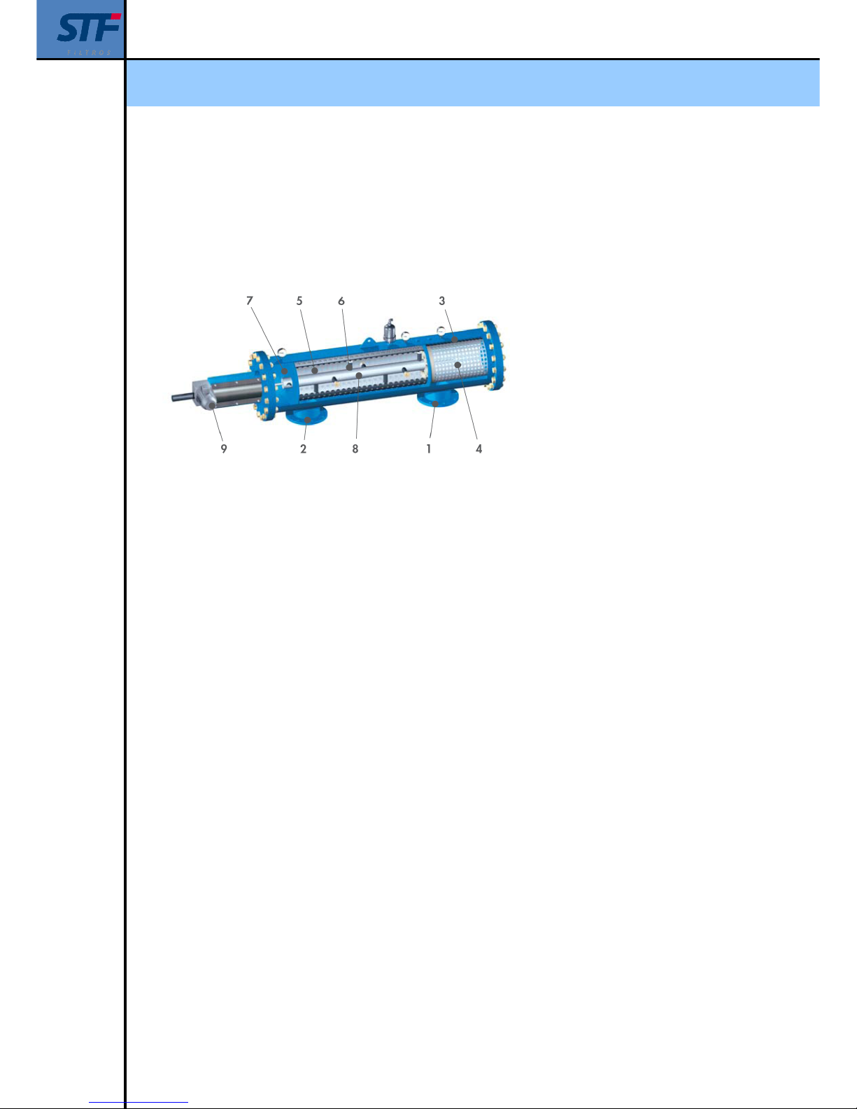
4. –FMA-2000 FILTER DESCRIPTION
The filter consists of an external casing where there are three different chambers. There is a
coarse screen that is used as a prefilter in the first prefiltration chamber that coincides with the
water inlet.
1 – Inlet
2 – Outlet
3 – Strainer chamber
4 – Strainer cartridge
5 – Filtering cartridge
6 – Filtering chamber
7 – Flushing chamber
8 – Scanner
9 - Motor drive
The water goes from outside to inside the filter. Once, the water gets inside the filter, it goes into
the second chamber that is called “filtration chamber”. It is in this chamber where the filtering
element is: FILTRATION SCREEN.
In this case water runs from the filter interior into the exterior. The solids remain in suspension
(filth) held back in the filtering element, that is it, the screen. This chamber coincides with the
filtered influent water inlet to the correct application: drinking water, process water, refrigeration
water, etc.
The held back dust forms a layer on the screen, that diminishes its load. The filter backwashing
bases on a third chamber, the backwashing chamber whose output is connected to the drainage
valve that allows water evacuation when the backwashing process starts. The backwashing
chamber is separated from the filtering by a special sealing
To finish with, as a very important element of this technology is the SUCTION SCANNER. This
scanner is the same place as the filtering cartridge central shaft would be, and it is hydraulically
connected to the backwashing chamber. At the same time, and in the filtering chamber area
where it is, the SUCTION NOZZLES are displayed perpendicularly. The nylon brushes nearly
reach the screen. The situation of these nozzles in the suction scanner has been studied for
getting into contact with the screen internal surface, thanks to the spiral movement that the
electric engine provides to the scanner: when combining a longitudinal and rotation movement.
Page 11

Installation, operation and maintenance manual - FMA 2000
Ref: 2000/CPF01/230/VH 11
5. – FMA-2000 PERFORMANCE
Water gets into the filter through the prefiltration chamber, where thick particles are
retained, as it was a strainer.
Water gets into the filtering chamber, goes through from inside to outside the FILTERING
SCREEN, producing the SURFACE MECHANIC. High quality water is obtained
according to the filtration degree choosen for the filtratrion screen which can vary from 10
microns to 2000 microns.
Dust remains on the thin screen interior what produces head loss between the filter inlet
and outlet gradually. Two analogic transducers will indicate the backwashing sequence
when the DP becomes 0.3 (3 m.c.a). There are other possibilities to make the filter
backwashing: Time backwashings, time and pressure combination, continuous
backwashing option.
When the pressure switch indicates 0.3 bar, the drain valve receive the opening order,
then it generates a pressure difference between outside (atmospheric pressure) and the
inside of the filter (working pressure) that is why fast running water which is produced,
goes through the screen and then goes outside through the nozzles internal orifice.
Besides this, at this very moment the starting order is also sent to the engine.
The result of these actions is: the suction effect of the nozzles on the screen dust and the
suction scanner spiral movement in the inside of the filter.
During the backwashing process that lasts 25 seconds, water is still being filtered and
goes on flowing to the system or application. This fact whis is is due to the filters design
allows that the backwashing water consumption is MINIMUM and the working system is
CONTINUOUS
Page 12
Installation, operation and maintenance manual - FMA 2000
Ref: 2000/CPF01/230/VH 12
6. – TECHNICAL CHARACTERISTICS
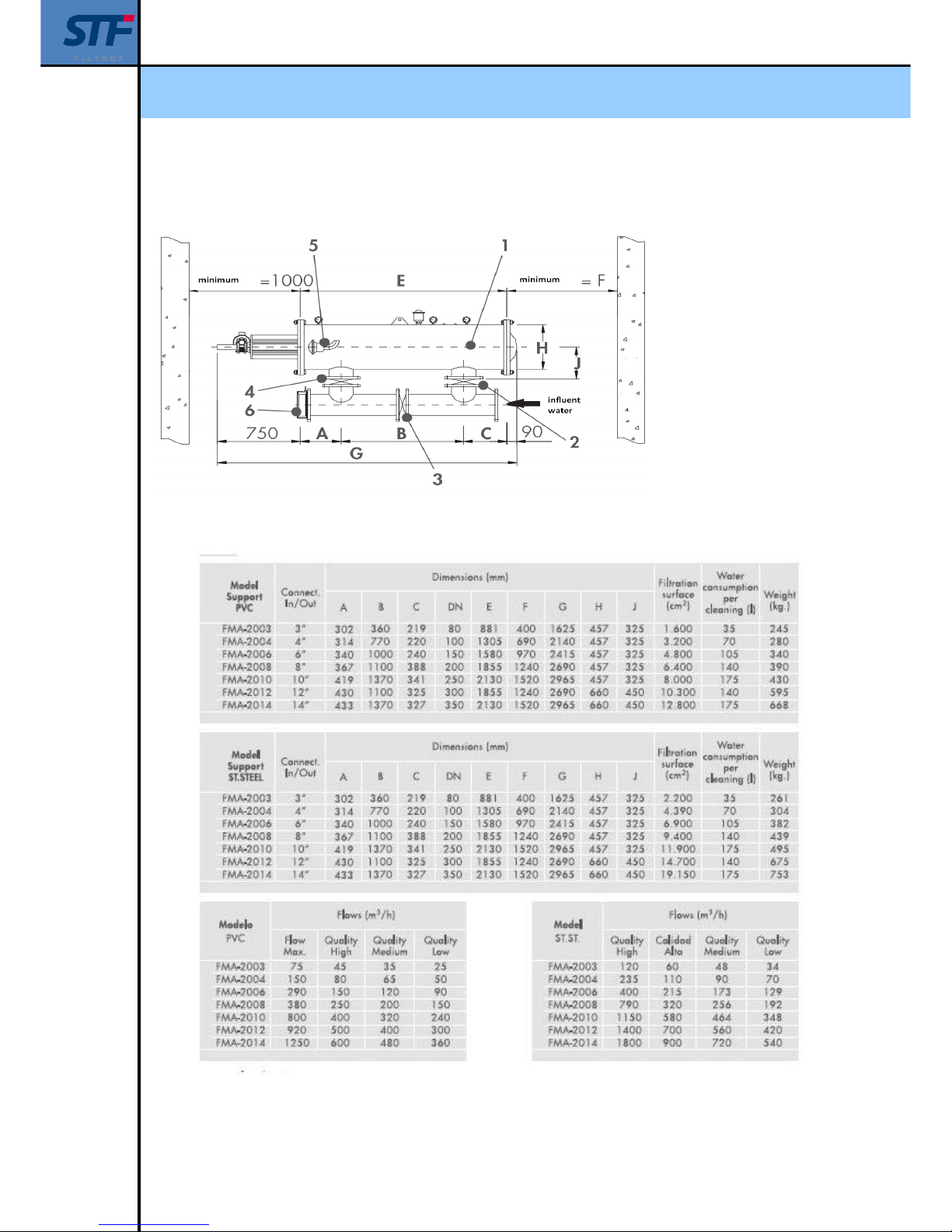
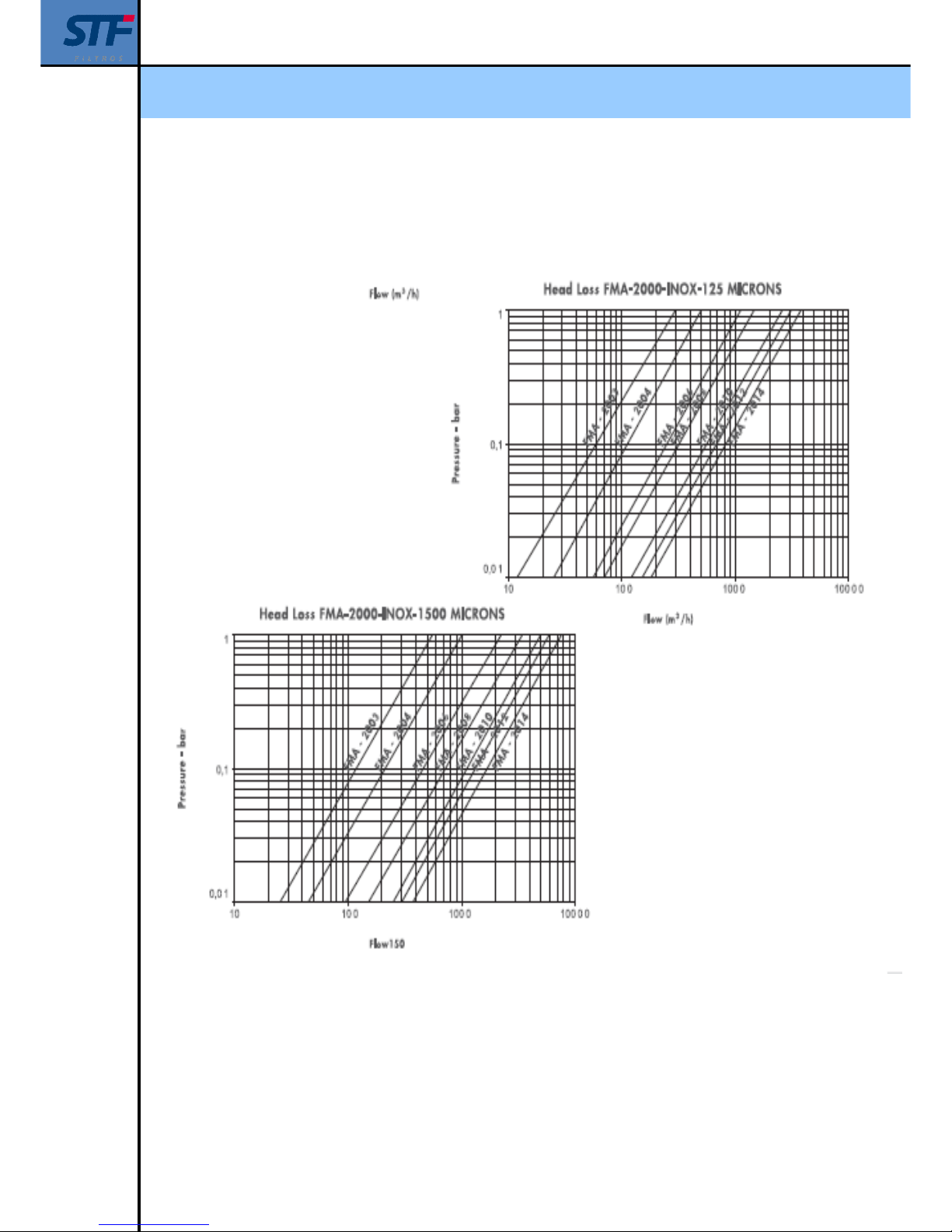
The flow is calculated for a 125 micron filtration degree, please, ask for other filtration degrees.
1 – Automatic filter Series 2000
2 – Butterfly valve inlet
3 – By-Pass valve
4 – Butterfly valve outlet
5 – Cleaning valve 2”
6 – Retaining valve (optional)
1 – Automatic filter Series 2000
2 – Butterfly valve inlet
3 – By-Pass valve
4 – Butterfly valve outlet
5 – Cleaning valve 2”
6 – Retaining valve (optional)
Page 13
Installation, operation and maintenance manual - FMA 2000
Ref: 2000/CPF01/230/VH 13
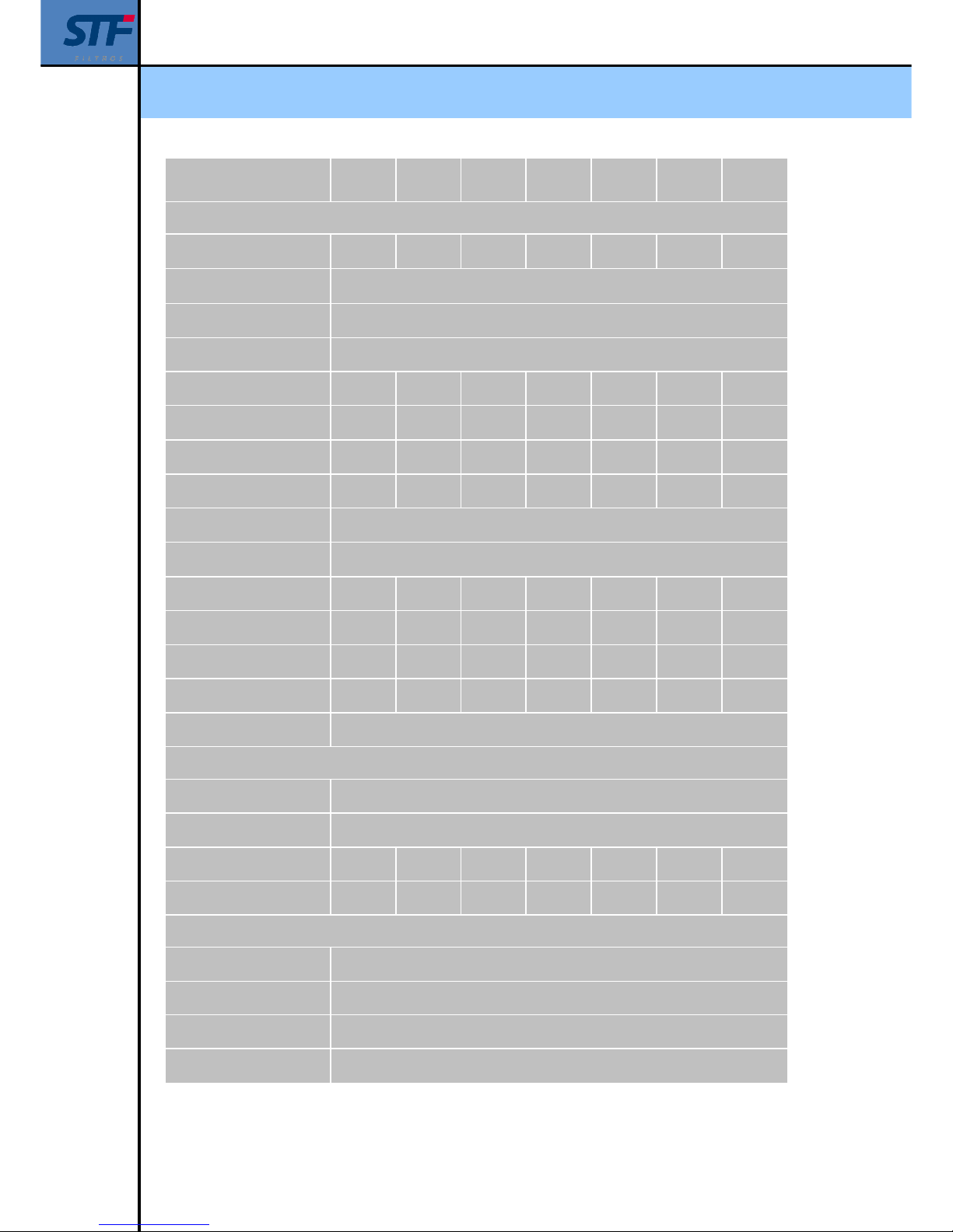
Filter model STF - FMA 2003 2004 2006 2008 2010 2012 2014
GENERAL CHARACTERISTICS
Inlet diameter /Outlet
(1)
DN-80
(3”)
DN-100
(4”)
DN-150
(6”)
DN-200
(8”)
DN-250
(10”)
DN-300
(12”)
DN-350
(14”)
Maximum/ minimum working
pressure
2 bar / 10 bar (for other working pressure, please ask us )
Fluid maximum temperature 50 ºC (u 95 ºC on demand)
PVC SCREEN
Maximum flow (m3/h) 75 150 290 450 800 920 1.250
Gross Filtration Surface
(cm2)
2.450 4.900 7.350 9.800 12.250 16.100 20.100
Net Filtration Surface (cm2) 1.600 3.200 4.800 6.400 8.000 10.300 12.800
Unladen weight (kg) 245 280 340 390 430 595 668
Filtration degree
1.000, 500, 300, 200, 125,100 micron
STAINLESS STEEL
SCREEN
Maximum flow (m3/h) 120 235 500 700 1.150 1.400 1.800
Filtration Surface (cm2) 2.650 5.380 7.990 10.600 13.210 16.500 21.300
Net filtration Surface (cm2) 2.200 4.390 6.900 9.400 11.900 14.700 19.150
Unladen weight (kg) 261 304 382 439 495 675 753
Filtration degree
1.000, 500, 300, 200, 125,100, 80, 50, 25, 20 y 10 micron
BACKWASHING
Backwashing valve Thread G-2”
Backwashing time 25 seconds
Backwashing flow (m3/h) 5 10 15 20 25 20 25
Water consumption (litros) 35 70 105 140 175 140 175
ELECTRICAL DATA
Operating voltage 220 V AC 50 Hz Single- phase(Optional 400 V AC Three-phase and 12 V DC)
Control tension 24 V DC (12 V DC supply 12 V DC)
Electrical engine power 0,37 kW (0,25 kW option 12 V)
Electrical engine
consumption
1,4 A
Page 14
Installation, operation and maintenance manual - FMA 2000
Ref: 2000/CPF01/230/VH 14
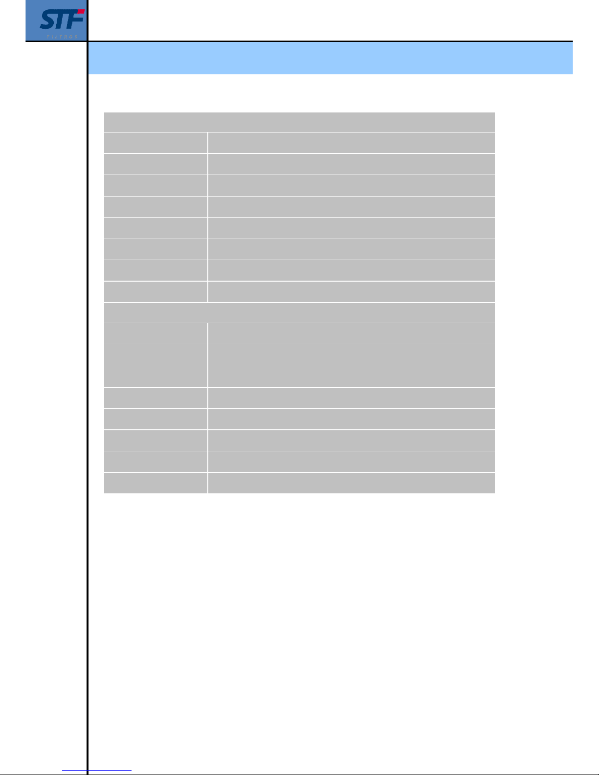
STANDARD MATERIALS
Filter body and covers S-235-JR Carbon steel
Finish treatment Epoxi-polyester polymerized baked oven finish powder coating.
Suction scanner AISI-304 stainless steel
Filtration screen AISI-316 stainless steel
Suction nozzles PVC with stainless steel AIS 316 ring and nylon fibers
Backwashing valves Brass body with stainless steel spring and axis and polyamide cover.
Screw Bichromated quality 5.6 and 5.8
Joints NBR – EPDM - Viton
SPECIAL MATERIALS (OPTIONAL)
Filter body and covers A-516 carbon steel / AISI 304 stainless steel / AISI 316 / SuperDuplex
Finish treatment
Intermal coating adequate for sea water and enternal coating for marine
environment
Suction scanner Duplex Stainless steel or Superduplex
Filtration screen 254 SMO stainless steel Avesta
Suction nozzles In stainless steel, Duplex or Superduples and nylon fibers.
Backwashing valves Hydraulic, electrical or pneumatic drive. Please, ask us for other materials.
Screw A2 o A4 stainless steel
Joints Please, ask us
Page 15
Installation, operation and maintenance manual - FMA 2000
Ref: 2000/CPF01/230/VH 15
Page 16
Installation, operation and maintenance manual - FMA 2000
Ref: 2000/CPF01/230/VH 16
Page 17
Installation, operation and maintenance manual - FMA 2000
Ref: 2000/CPF01/230/VH 17
7. – IDENTIFICATION PLATE
All the equipments are identified by means of an identification plate stuck to the filter.
The following information is included in the identification plate:
Equipment serial
Model
Equipment serial number
CE certificate
Page 18
Installation, operation and maintenance manual - FMA 2000
Ref: 2000/CPF01/230/VH 18
8. – INSTALLATION INSTRUCTIONS
Take precautions to prevent the filter from striking, the equipment lifting by means of the
upper anchor points.
Make sure that the installation point has the minimum operation pressure.
o The backwashing pipe has to be measured so that it gets a minimum flow head
loss of 25 m³/h.
o In installations with a working pressure superior to 6 bar, it is advisable to install
a ball valve in the backwashing pipe to adjust the backwashing flow.
NOTE
THE MINIMUM WORKING PRESSURE IS 2 BAR BETWEEN THE FILTER
OUTLET AND THE DRAIN VALVE.
IN CASE THE DRAIN IS RECONDUCTED, IT IS NECESSARY TO
INCREASE THE WORKING PRESSURE IN ORDER TO COMPENSATE
FOR THE HEAD LOSS THAT MAY APPEAR IN THE DRAIN PIPE
Install the filter horizontally, check that there is enough room so that the filter can be
easily accessed in safe conditions for future treatments and for its maintenance. See se
section 6.
Position the filter in the driving obeying the arrows indicating the water running direction.
Inlet and outlet shut-off valves are recommended to be installed in order to insulate it. It is
recommended to install a by-pass in order to avoid power cuts during the maintenance.
It is recommended to install an outlet backflow in order to avoid water hammer on the
filter.
According to section 12.1 the electrical wiring can only be installed by a skilled
electrician.
In the filter installation it has to be avoided that water splashes over the electrical
components or the control panel.
Page 19
Installation, operation and maintenance manual - FMA 2000
Ref: 2000/CPF01/230/VH 19
9. – STARTING INSTRUCTIONS.
Check previous section instructions.
Check the hydraulic circuit (see section 15) that provides the backwashing valve with
water, making sure that:
o ¾” filter is clean.
o The ball valve is open.
o The 3 way valve value is in AUTO position.
o Start with the following shut-off valves configuration:
o Inlet valve: OPEN
o Outlet valve: CLOSE.
o By – pass (If it exists): CLOSE
Switch on the filter, put the circuit breaker ON
Make sure that the programmable relay is on the selected option RUN
Manual backwash by pressing the limp button.
The backwashing cycle evolution is detailed in section 12.2.
Open outlet valve.
A drop in pressure and water flow increase is produced when the water mains is filled in.
That is why it is advisable to install an outlet pressure valve, making sure that the water
mains filling is controlled.
NOTE
IN CASE A SUPPORTING PRESSURE IS NOT INSTALLED, DURING THE
WATER MAINS FILLING, CLOSE THE OUTLET VALVE UNTIL GETTING 2
BAR IN THE CLEAN WATER PRESSURE GAUGE.
ONCE THE WATER MAINS IS PRESSURIZED, OPEN THE OUTLET
VALVE TO GET A CORRECT OPERATION.
Make sure that water flow and pressure installation correspond with the maximum values
defined for this manual model. See section 6
Check the equipment operation and the head loss when the starting up is finished.
Page 20
Installation, operation and maintenance manual - FMA 2000
Ref: 2000/CPF01/230/VH 20
NOTE
THE FILTER CAN START THE BACKWASHING CYCLE AUTOMATICALLY
WHEN THE 0.3 PRESSURE DIFFERENCE BETWEEN THE INLET AND
THE OUTLET RISES OVER 0.3 BAR.
NOTE
IN CASE OF HAVING SEVERAL FILTERS WORKING IN PARALEL WITH
COMMON CONTROL PANEL, PLEASE NOTE THAN THE FILTER WHICH
MANAGES THE CLEANING IS THE ONE WITH THE PRESSURE
TRANSMITTERS / PRESSURE SWITH INSTALLED IN ITS BODY. PLEASE
TAKE THIS INTO ACCOUNT IN CASE OF MAINTENANCE.
Page 21
Installation, operation and maintenance manual - FMA 2000
Ref: 2000/CPF01/230/VH 21
10. – MAINTENANCE INSTRUCTIONS.
Switch off the enery supply filter before any maintenance operation.
Make sure that the filter is unpressurized before loosening the screws.
Avoid splashes and water leaks by minimizing the personnel risk sliding or being
electrocuted and the damage that humidity can cause to the equipment.
After completing the treatment rearm the transmission mechanism protecting covers.
Make the manual backwashing of the filtering cartridge by using pressurized. If necessay
acid or any other chemical products will be used. This process has to be done following
the material instructions and not putting the operator or the rest of the people at risk.
Drain the equipment when it is not used for long time.
NOTE
OPEN AND CLOSE THE VALVES SLOWLY AND GRADUALLY.
Page 22
Installation, operation and maintenance manual - FMA 2000
Ref: 2000/CPF01/230/VH 22
11. – PREVENTIVE MAINTENANCE SCHEDULE
MAINTENANCE
TIME ELEMENT
ACTION
EXTERNAL
Working revision
1000 backwashing
cycles
Complete filter
Filter on + manual backwashing button.
Control:
Engine starting
Valve opening
Efective backwashing cycle (P1 = P2)
Anticorrosion
treatment
12 months
FMA casing
(element 9)
Review anticorrosion treatment in the necessary points.
Apply Epoxi - Polyester treatment
Turret 6 months
Spindle
(element 1.23)
Desmantle the spindle protection (1.32) and lateral rolling
press
Clean and grease spindle both sides.
Use the grease supplied by STF-Filtros.
Rim watertightness 6 months
Rim watertightness
(element 1.10)
Revise the waterlightness of the element 1.10.
Replace the inside joints:
Ø45x4 o-ring seal (element 1.9)
NI joint– 150 20x28x5,5 (element 1.14)
EQ-16 quadric joint (element 1.15)
Scraper 20X28X4,8/7 (element 1.16)
Pressure line 1 week
Intake filter
(element 18)
Intake filter backwashing and microtubes for supplying
water to the backwashing valve.
INTERNAL
Anticorrosion
treatment
12 months
FMA casing
(element 9)
Review anticorrosion treatment in the necessary points
Apply Epoxi - Polyester treatment
Suction nozzle 12 months
Suction nozzle
(element 24.1)
Suction nozzles condition revision, nylon fibers condition,
cartridge proximity.
Smoothing cartridge 12 months
Smoothing cartridge
(element 28)
Smoothing cartridge backwashing
Filtering cartridge Inactivity period
Filtering cartridge
(element 29)
Backwash manually by using water under pressure, if
necessary, acid or any other chemicals products will be
used
Joints 12 months
Inside joints
Element 11
Element 27.6
Element 27.8
Element 30
Revise inside joints. In case they are deteriorated, they
will be replaced.
Page 23
Installation, operation and maintenance manual - FMA 2000
Ref: 2000/CPF01/230/VH 23
12. – CONTROL PANEL
When a FMA-2000 filter model is supplied, all the electrical connections between the control
panel and the actuators have already been installed and checked by the manufacturer.
The equipment supply is 230V CA, 50Hz in a standard way. In case of variants, this should be
checked with the manufacturer
BEWARE!
DURING THE STARTING, IT SHOULD BE CHECKED THAT THE ENGINE
TURNING CORRESPONDS WITH THE FILTER PROGRAMMING IN
PANELS WHICH ARE SUPPLIED BY TRIPHASE CURRENT.
DESCRIPTION
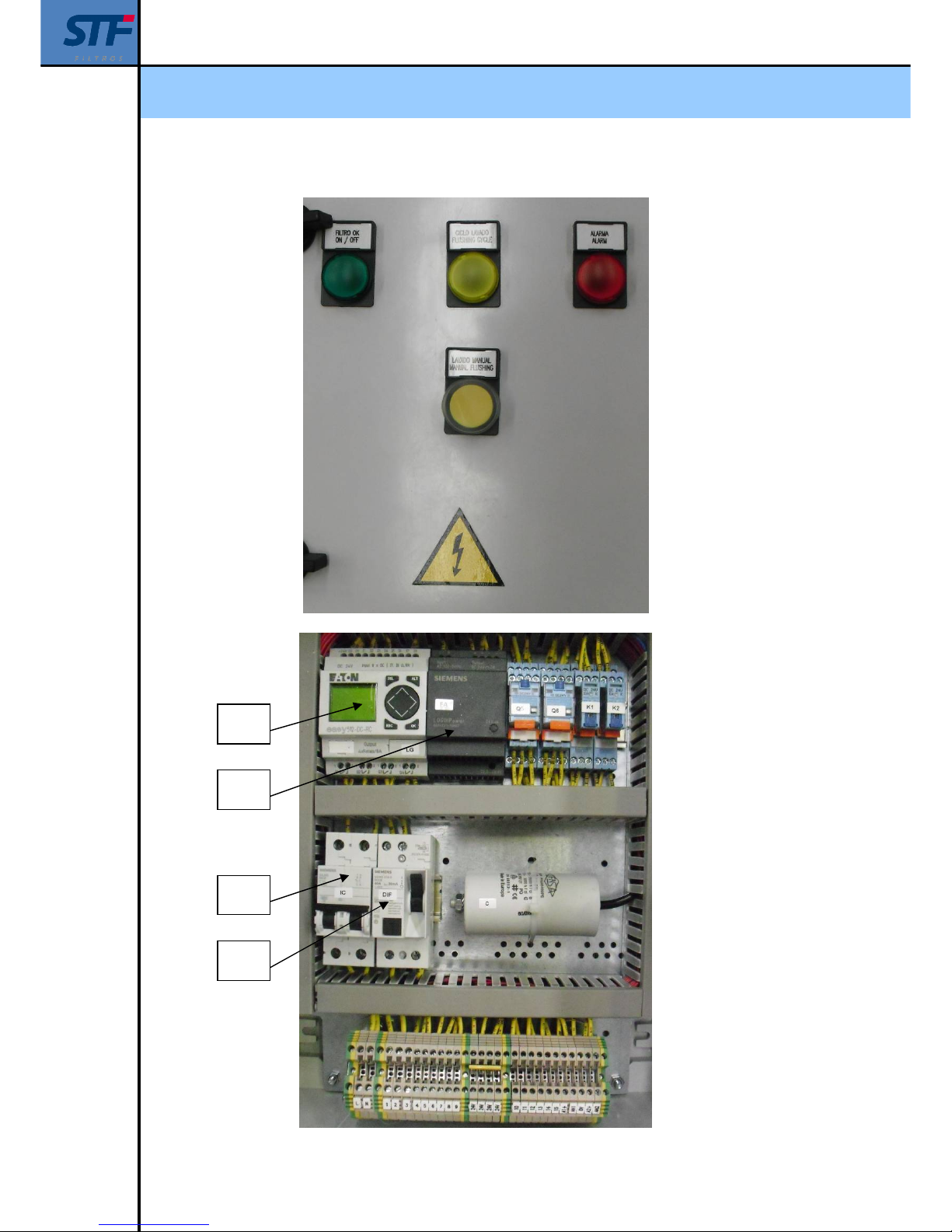
The different monitoring and control components can be found in the control panel :
Pilot lights:
o Green: It turns on when there is energy.
o Yellow: It turns on when a backwashing cycle is produced.
o Red: It turns on when there is an alarm.
The push button has two functions:
o To generate a manual backwashing cycle.
o To rearm the equipment when it fails.
Thermic magnet (IC).
o 1 + N, 10A C
Differential (DIF).
o 1 + N, 40A 30 mA.
Power supply (FA).
o 230 V / 24 VCC (1ª)
A relay that can be programmed(LG).
o EASY 24V DC 8entries / 4LCD outputs.
The messages that appear in the relay that can be programmed are specified in section 12.2 and
13.
Page 24
Installation, operation and maintenance manual - FMA 2000
Ref: 2000/CPF01/230/VH 24
LG
FA
IC
DIF
Page 25
Installation, operation and maintenance manual - FMA 2000
Ref: 2000/CPF01/230/VH 25
12.1. – CONNECTION
BEWARE!
ELECTRICAL DISCHARGE RISK. THE OPERATIONS INDICATED WITH
THIS SYMBOL SHOULD BE CARRIED OUT ONLY BY SKILLED
TECHNICAL STAFF.
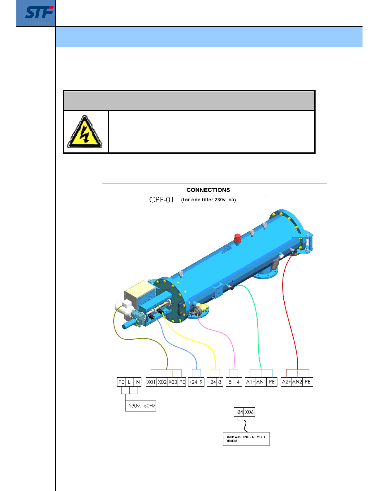
The supply, sensor and equipment actuators connection is carried out in the lower terminal block
according to the following specifications:
Page 26
Installation, operation and maintenance manual - FMA 2000
Ref: 2000/CPF01/230/VH 26
Panel supply: PE – L – N
Engine supply input: PE – 1 – 2 – 3
Electrovalve supply output: 4 – 5
Backwashing inlet/ external rearm: +24 – 6
Front limit switch inlet: +24 – 8
Back limit switch inlet: +24 – 9
Clean water pressure transducer entry signal: A1+ - AN1 – PE
Wastewater pressure transducer entry signal: A2+ - AN2 – PE
Alarm (tension-free contact)
o Common: 10
o N.C: 11
o N.O: 12
Backwashing cycle (tension-free contact)
o Common: 13
o N.C: 14
o N.O: 15
COMMUNICATION STANDARD SIGNALS
ENTRY:
MANUAL BACKWASHING / REARM: +24 – 6
OUTPUT:
ALARM (TENSION-FREE CONTACT): 10 – 11 – 12
BACKWASHING CYCLE (TENSION-FREE CONTACT): 13 – 14 – 15
Page 27
Installation, operation and maintenance manual - FMA 2000
Ref: 2000/CPF01/230/VH 27
12.2. – PERFORMANCE
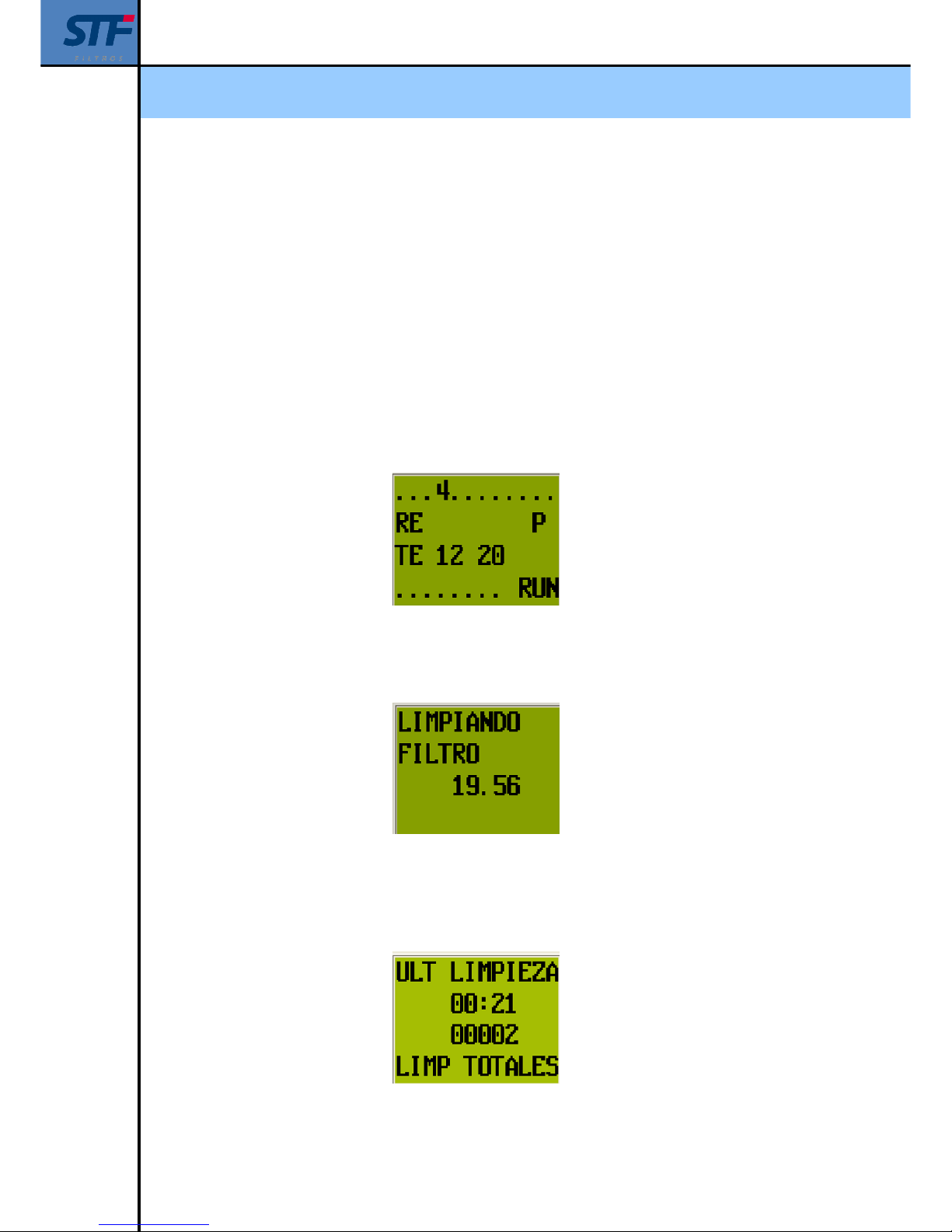
The start screen shows the following information, the upper parameters...3.4... indicate the entry
signals into the programmer.
Paramater 1 – Manual backwashing pushbutton
Parameter 2 – Pressure switch.(Pressure transducers are used by default)
Parameter 3 – Front limit switch. Filter 1
Parameter 4 – Back limit switch. Filter 1
Besides this, the date and time appear on the display, (RUN) if the programmer is on or (STOP) if
it is stopped. In the event of the equipment is stopped it will not make backwashing cycles. P
indicates the push-button
Start screen image
When a backwashing cycle starts a screen that monitors the time in seconds and milliseconds
appear. When the cycle finishes the start screen appears again.
Filter backwashing screen image
Pulse to check the time that has passed from the last backwashing (it appears in hours and
minutes) and the total equipment backwashings number by pressing the key or while the
start screen is on.
Last backwashing & total backwashings screen image
Page 28
Installation, operation and maintenance manual - FMA 2000
Ref: 2000/CPF01/230/VH 28
12.3. –MODIFYING PARAMETERS
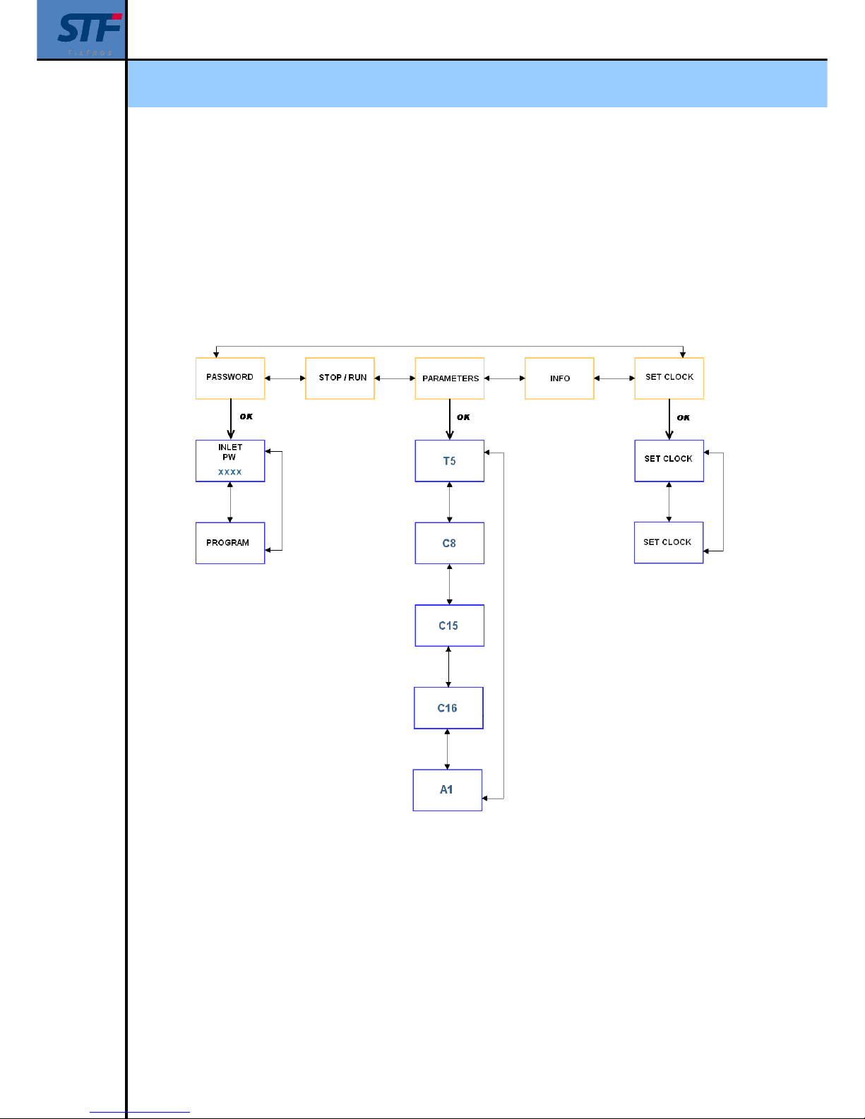
It is useful to observe the diagram that is shown in order to have access to the different program
functions. In the same diagram the main menu and several submenus appear. Pulse OK in order
to have access to the main menu functions.
Press keys in order to change the menu selection. Press OK key in order to have access
and ESC to turn back.
Page 29

Installation, operation and maintenance manual - FMA 2000
Ref: 2000/CPF01/230/VH 29
PASSWORD: It allows you to have access to the program, it is protected to avoid non-
authorized modifications by the manufacturer.
RUN / STOP: It allows you to stop the running cycle when the STOP key is pressed.
The symbol appears next to the present condition on the LCD screen. Use keys in order
to change it and select STOP RUN (a flickering appears) and press OK.
PARAMETERS: It allows you to have access to the installation modifiable parameters
Press keys in order to select the PARAMETERS (a flickering appears) and press OK. The
parameters are the following:
T5– Time between backwashings
It shows the backwashing time in hours and minutes. These figures turn back to zero every time a
manual or automatic backwashing is carried out. This valor can be modified according to
installation needs.
I1 – Backwashing time value in hours and minutes (H:M)
T – Time in hours and minutes (H:M) since last backwashing
Press keys to move over I1. Press OK to modify values by using keys and .
When finished, press OK in order to accept the new value.
Press ESC to quit.
C8 – Language selection meter.
It allows you to select the language of the messages monitorized by the programmer. It can be
done in Spanish and English.
o 1 – Spanish (standard)
o 2 – English
Press keys to move over I1, press OK to modify values by using keys and .
When finished, press OK again to accept the new value.
Press ESC to quit
C15-Consecutive backwashing meter
It shows the consecutive automatic backwashings number during which the pressure switch
keeps sending a continuous signal. In this case the value is 20. At the moment when the
consecutive automatic backwashings get this value, the filter will go into alarm. (Consult ALARM
section)
Page 30
Installation, operation and maintenance manual - FMA 2000
Ref: 2000/CPF01/230/VH 30
S – Setpoint value
C – Meter real value
Press keys to move over S. Press OK to modify values by using keys and .
When finished, press OK again to accept the new value.
Press ESC to quit
C16– Switch pressure & pressure transducers selection.
It allows to control the filter pressure differential. It is possible to do it by means of the pressure
transducers or pressure switches.
S – Setpoint value:
o 1 – Work with pressure switch
o 2 – Work with pressure transducers (standard)
Press keys to move over I1. Press OK to modify values by using keys and .
When finished, press OK again in order to accept the new value.
Press ESC to quit.
BEWARE!
IT IS NOT ADVISABLE TO MODIFY THIS VALUE. IF WATER QUALITY
WORSENS IN A SPECIFIC MOMENT, THIS VALUE WILL BE MODIFIED
TO A HIGHER ONE SO THAT THE FILTER CAN RECOVER
AUTOMATICALLY.
A1 – Pressure difference set value when working with pressure transducers.
It shows the pressure difference of the automatic backwashing cycle start when using pressure
transducers:
I1 – Effluent water pressure reading
I2 – Influent water pressure reading
OS – Set value
Press keys to move over OS. Press OK to modify values by using keys and .
When finished, press OK again in order to accept the new value.
Press ESC to quit.
Page 31
Installation, operation and maintenance manual - FMA 2000
Ref: 2000/CPF01/230/VH 31
BEWARE!
IT IS NOT ADVISABLE TO MODIFY THIS VALUE.
THE DIFFERENTIAL SHOULD NEVER BE INCREASED, IT CAN ONLY BE
MODIFIED TO LOWER VALUES IN ORDER TO BACKWASH.
Page 32

Installation, operation and maintenance manual - FMA 2000
Ref: 2000/CPF01/230/VH 32
13. – WARNINGS AND ALARMS
1. When the programmer makes the number of backwashings consecutively indicated in
parameter C2 (the setpoint is 20) there is no possibility to go on filtering, the safety
device that will stop the filter backwashing will activate.
The panel alarm light will turn on and the inscription ALARM 20 CONSECUTIVE
BACKWASHINGS will appear on the programmer screen.
This alarm indicates that the pressure differential gets to the electrical panel, this can be
due to a measure sensor failure, dust in the filters or dust in the water to be filtered.
Unblock the pressure switch or press the START, REARM, ALARM button in order to
delete the alarm.
2. If during the backwashing any of the engines running is stopped, the message LIMIT
SWITCH ALARM will appear on the screen.
This alarm does not need to be rearmed, it is necessary to check that the limit switch
signal gets correctly to the panel, then backwash twice.
If this is not corrected, please contact the manufacturer.
.
Page 33
Installation, operation and maintenance manual - FMA 2000
Ref: 2000/CPF01/230/VH 33
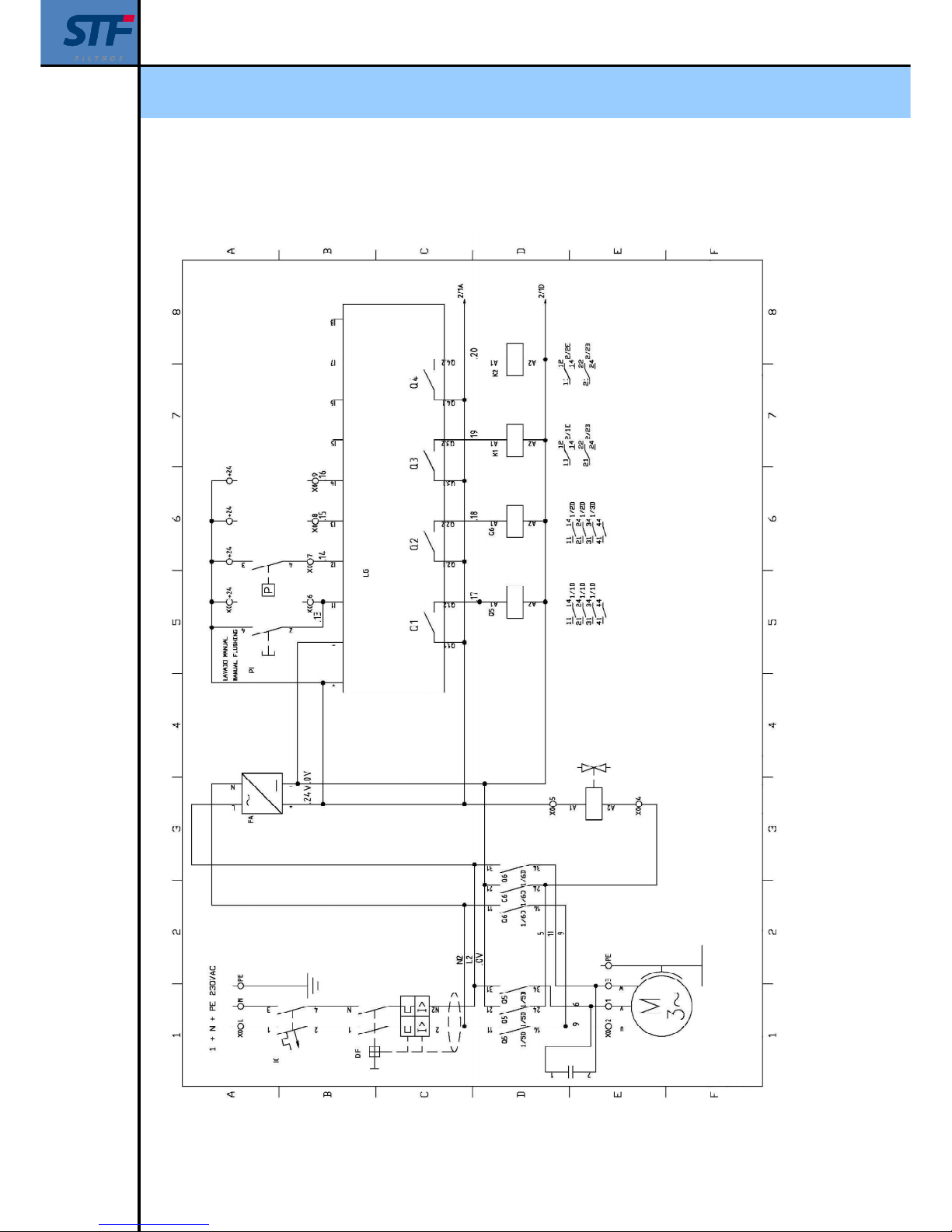
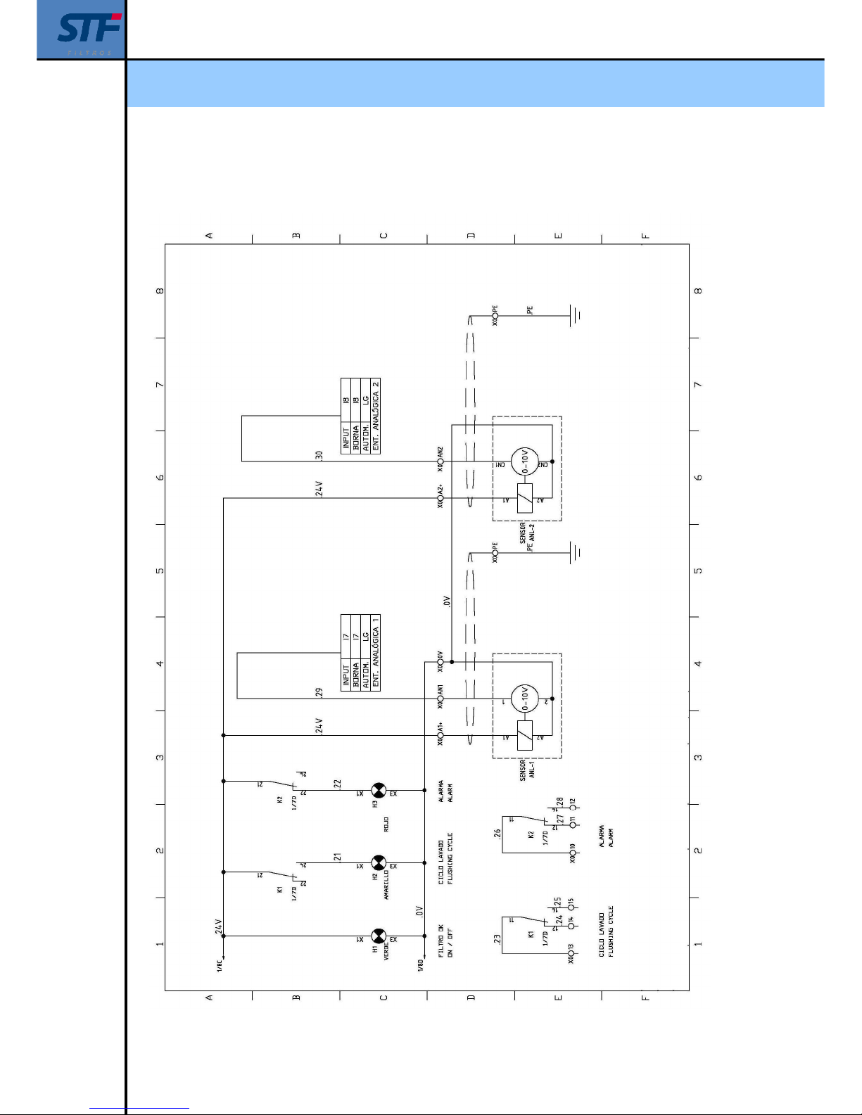
14. – ELECTRIC DIAGRAM
Layout 1 of 2
Page 34
Installation, operation and maintenance manual - FMA 2000
Ref: 2000/CPF01/230/VH 34
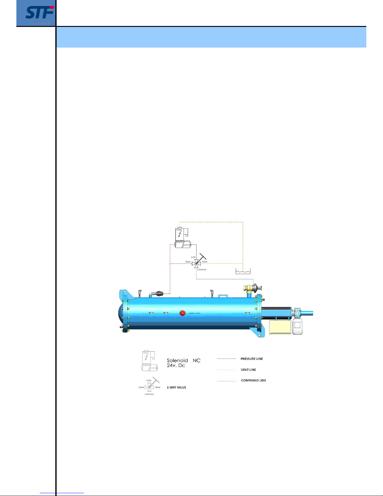
Layout 2 of 2
Page 35
Installation, operation and maintenance manual - FMA 2000
Ref: 2000/CPF01/230/VH 35
15. – HYDRAULIC CIRCUIT.
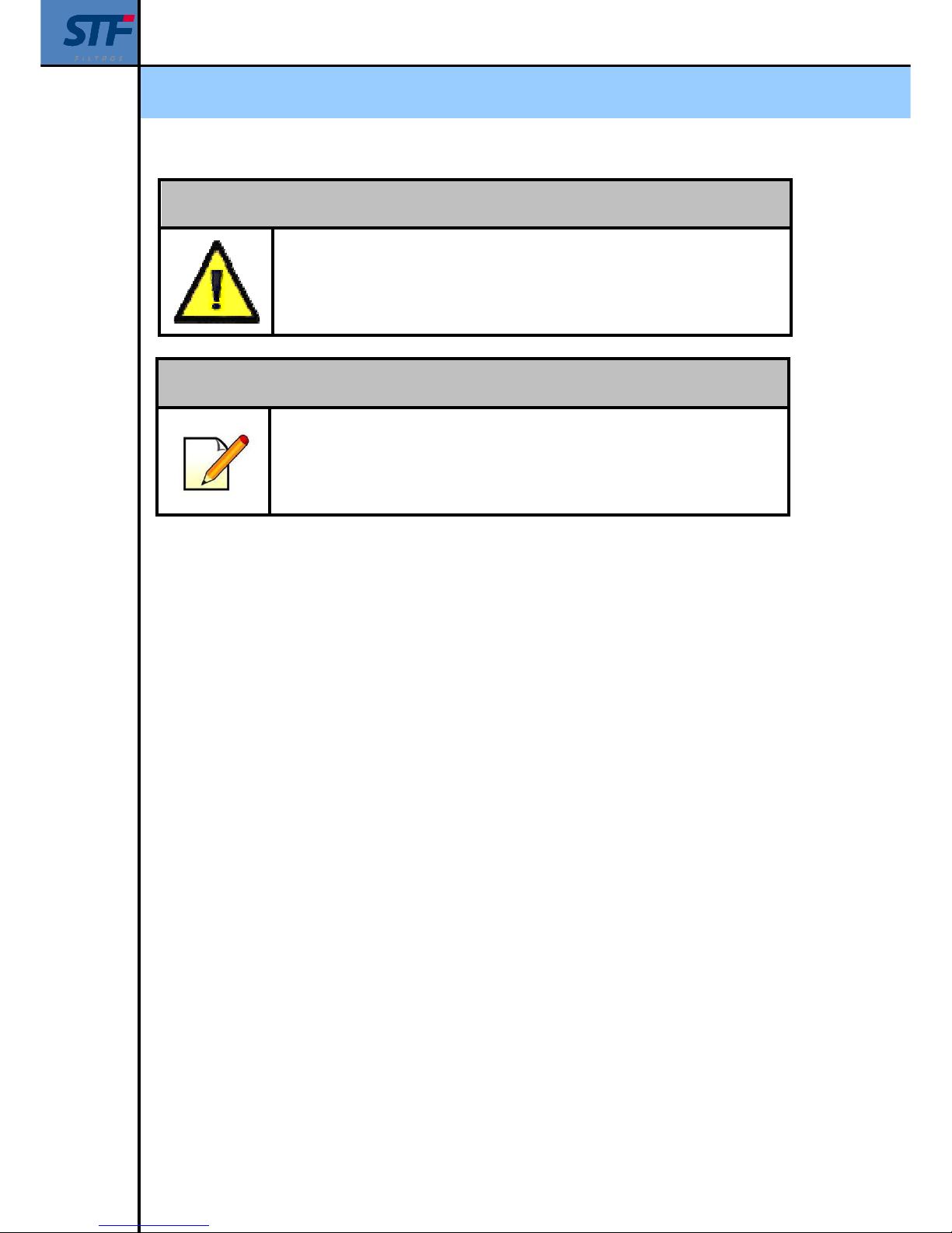
The filter has a hydraulic valve for draining the backwashing flow. The valve remains closed
because of the internal spring, and it opens when introducing water in the lower chamber and it
closes when the drain is in process.
The valve has a mechanic regulation that allows to adjust the backwashing flow in isntallations
with a pressure superior to 6 bar.
The opening and closing process is automated by means of a 24V DC NC solenoid (normally
closed). It is specified in the drawing below.
The 3-way valve has to remain in AUTO position, allowing the possibility to operate manually with
the OPEN and CLOSE positions.
Page 36
Installation, operation and maintenance manual - FMA 2000
Ref: 2000/CPF01/230/VH 36
BEWARE!
FILTER THAT PROTECTS THE CIRCUIT MAINTENANCE BY MEANS OF
USUAL BACKWASHINGS.
LONG DISTANCE DRAINAGE CONDUCTION CAN RESULT IN
OPERATION PROBLEMS.
NOTE
THE PREVIOUS DIAGRAM IS VALID ONLY FOR STANDARD
EQUIPMENTS WITH MAXIMUM 10 BAR PRESSURE
ASK THE MANUFACTURER IN CASE OF DIFFERENT PRESSURES.
Page 37
Installation, operation and maintenance manual - FMA 2000
Ref: 2000/CPF01/230/VH 37
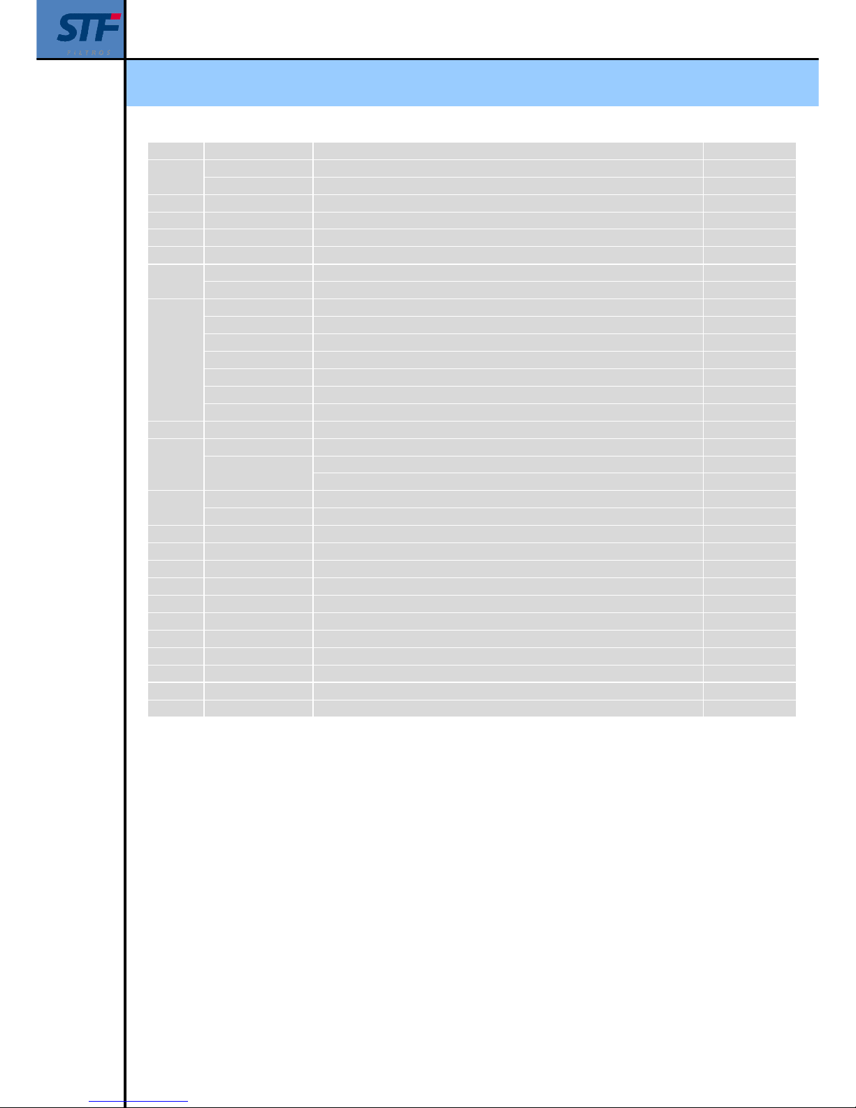
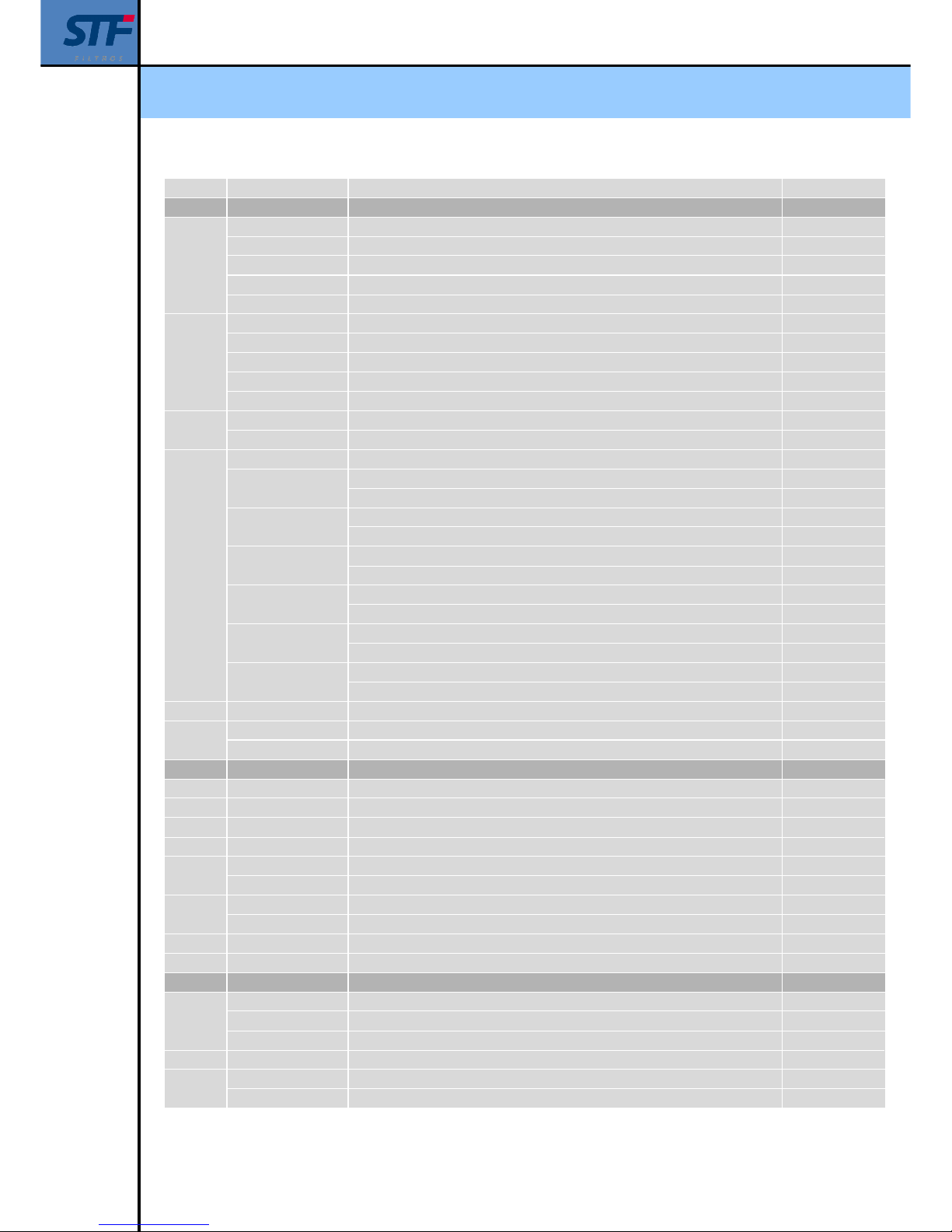
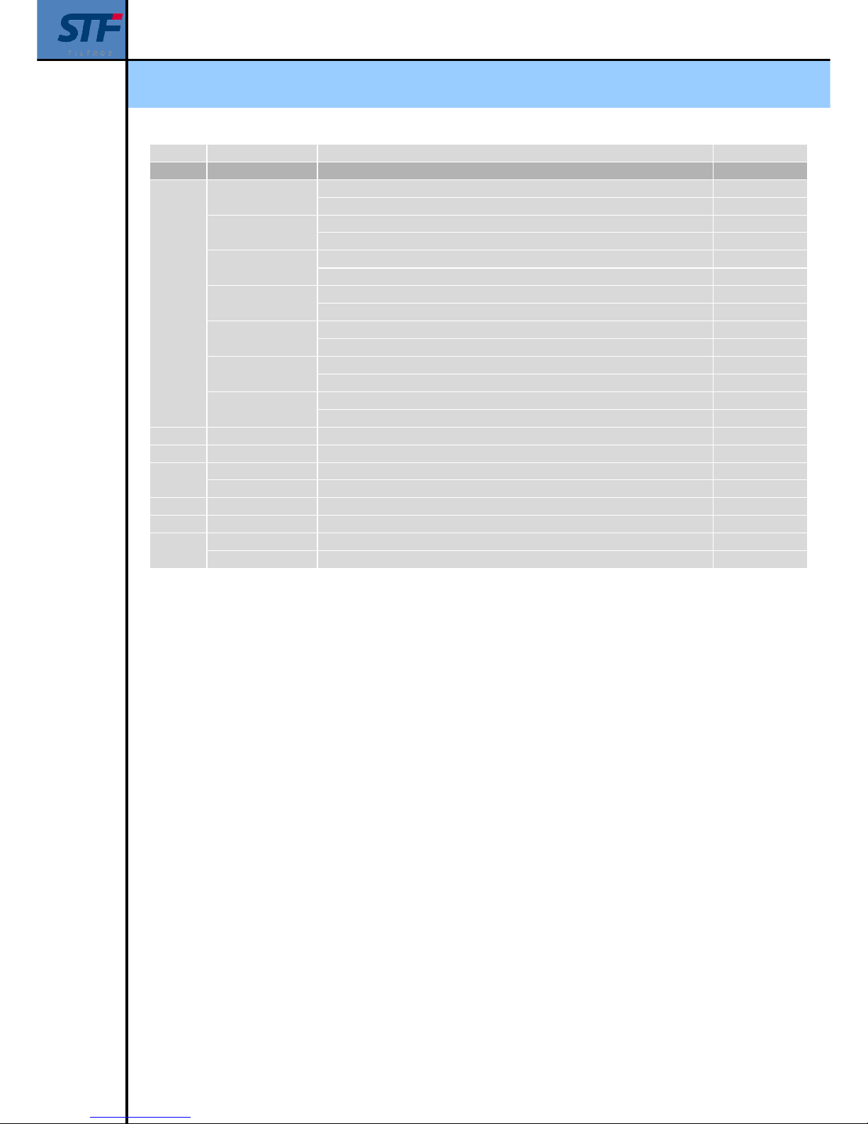
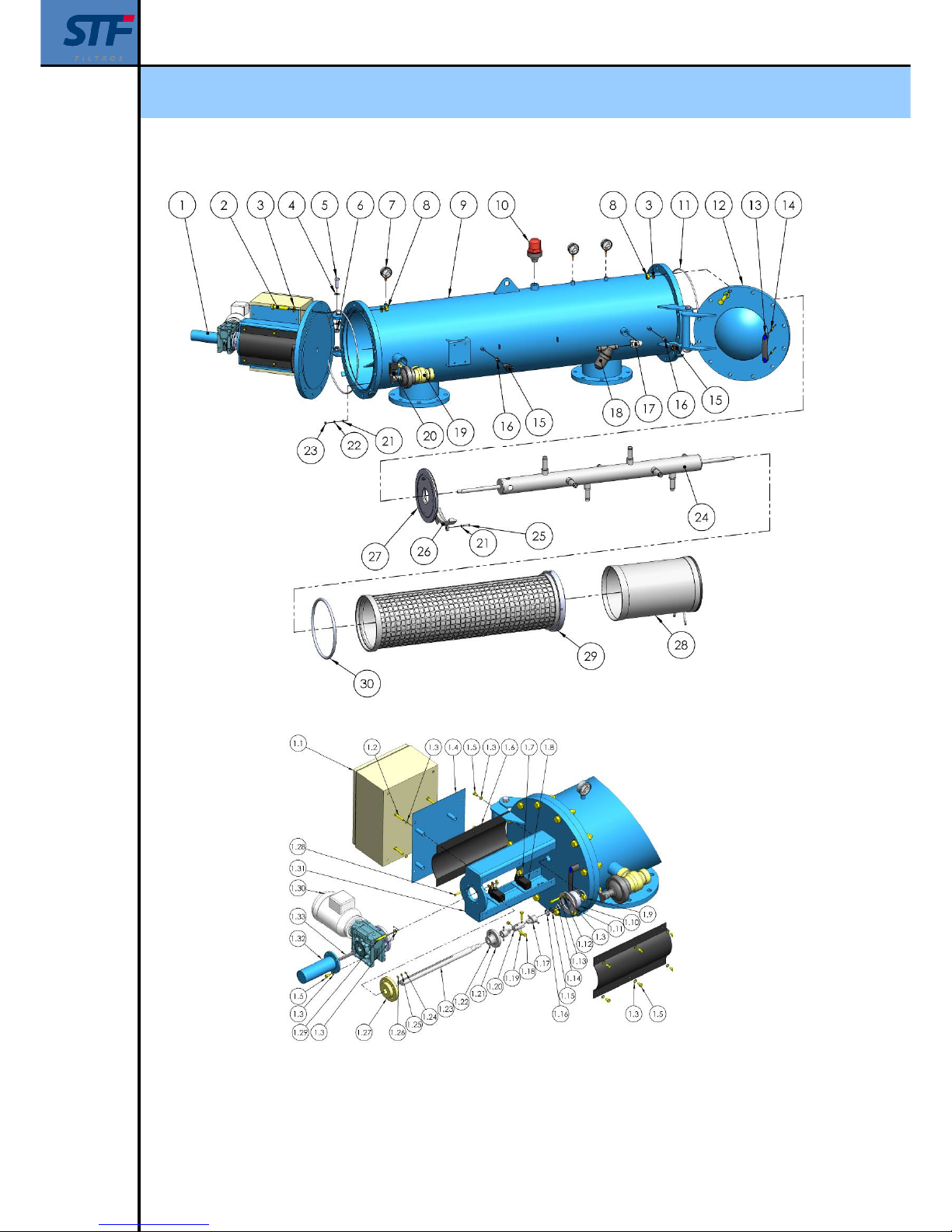
16. – EXPLOSION DRAWING
Order Equipment model Description Number of units
1 TURRET
1.1
FMA-2003 - 2014 Electric panel CPF-01 ( for 1 filter, 230v. ca panel ) 1
FMA-2003 - 2014 Electric panel CPF-04 ( for 4 filters 230v. ca panel ) 1
FMA-2003 - 2014 Electric panel CPF-10 ( for 10 filters 230v. ca panel ) 1
FMA-2003 - 2014 Electric panel CPF-01-400 (for 1 filter 400v. ca panel) 1
FMA-2003 - 2014 Electric panel CPF-04-400 (for 4 filters 400v. ca panel ) 1
FMA-2003 - 2014 Electric panel CPF-10-400 (for 10 filters 400v. ca panel) 1
FMA-2003 - 2014 Electric panel CPF-01-12 (for 1 filter 12v. cc panel ) 1
FMA-2003 - 2014 Electric panel CPF-03-12 (for 3 filters 12v. cc panel) 1
1.2 FMA-2003 - 2014 M8x80 screw 4
1.3 FMA-2003 - 2014 M8 washer 15
1.4 FMA-2003 - 2014 Electric panel support plate 1
1.5 FMA-2003 - 2014 M8x20 screw 12
1.6 FMA-2003 - 2014 Protection cover 2
1.7 FMA-2003 - 2014 M5x30 screw 4
1.8 FMA-2003 - 2014 Omron limit switch 2
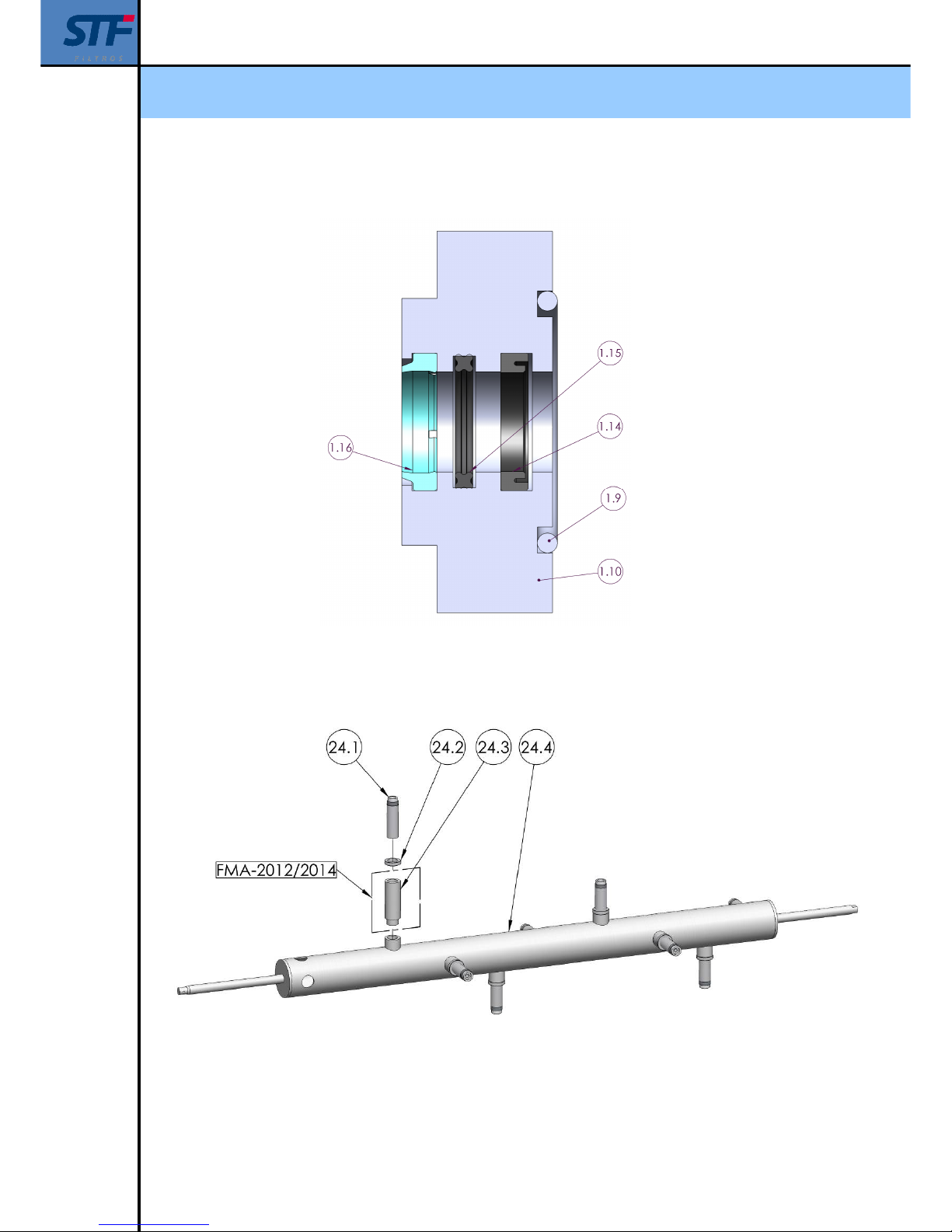
1.9 FMA-2003 - 2015 ø45x4 O-ring 1
1.10 FMA-2003 - 2014 Rim watertightness 1
1.11 FMA-2003 - 2014 Rim watertightness washer 1
1.12 FMA-2003 - 2014 M8 washer 3
1.13 FMA-2003 - 2014 M8x45 screw 3
1.14 FMA-2003 - 2014 NI-150 20x28x5,5 Joint 1
1.15 FMA-2003 - 2014 Quadric joint EQ-16 1
1.16 FMA-2003 - 2014 AUASOB 20x28x4,8/7 scraper 1
1.17 FMA-2003 - 2014 Male crosshead 2
1.18 FMA-2003 - 2014 M8x35 screw 2
1.19 FMA-2003 - 2014 M8 nut 2
1.20 FMA-2003 - 2014 Female crosshead 1
1.21 FMA-2003 - 2014 Limit switch 1
1.22 FMA-2003 - 2014 M6x12 screw 8
1.23 FMA-2003 - 2014 Shaft 1
1.24 FMA-2003 - 2014 M6 nut 4
1.25 FMA-2003 - 2014 M6 washer 4
1.26 FMA-2003 - 2014 M6 washer 4
1.27 FMA-2003 - 2014 Bronze nut 1
1.28 FMA-2003 - 2014 M6x35 screw 4
1.29 FMA-2003 - 2014 M8x50 screw 4
1.30
FMA-2003 - 2014 Gear engine Ca 0,37Kw 27rpm Fs-1,5 with an outlet flange 1
FMA-2003 - 2014 Gear engineCc 12v 27rpm with an outlet flange 1
1.31
FMA-2003 - 2010 Engine cover side 1
FMA-2012 / 2014 Engine cover side 1
1.32 FMA-2003 - 2014 Spindle protection 1
1.33 FMA-2003 - 2014 Shaft key 1
2
FMA-2003 - 2010 M18x90 screw 24
FMA-2012 / 2014 M24x110 screw 40
Page 38
Installation, operation and maintenance manual - FMA 2000
Ref: 2000/CPF01/230/VH 38
Order Equipment model Description Number of units
3
FMA-2003 - 2010 M18 washer 48
FMA-2012 / 2014 M24 washer 80
4 FMA-2003 - 2014 M16 washer 12
5 FMA-2003 - 2014 M16x50 screw 4
6 FMA-2003 - 2014 M16 nut 4
7 FMA-2003 - 2014 Glycerin pressure gauge Macho Gas-1/4" 3
8
FMA-2003 - 2010 M18 nut 24
FMA-2012 / 2014 M24 nut 40
9
FMA-2003 Casing FMA-2003 1
FMA-2004 Casing FMA-2004 1
FMA-2006 Casing FMA-2006 1
FMA-2008 Casing FMA-2008 1
FMA-2010 Casing FMA-2010 1
FMA-2012 Casing FMA-2012 1
FMA-2014 Casing FMA-2014 1
10 FMA-2003 - 2014 Macho Gas-1" air release 1
11
FMA-2003 - 2010 ø456x6,99 O-ring joint 2
FMA-2012 / 2014
ø633.48x6,99 O-ring joint 2
ø660x8 O-ring joint 2
12
FMA-2003 - 2010 Prefiltration cover side 1
FMA-2012 / 2014 Prefiltration cover side 1
13 FMA-2003 - 2014 Handle 2
14 FMA-2003 - 2014 M8x35 screw 4
15 FMA-2003 - 2014 Pressure transducer Macho Gas-1/4" 2
16 FMA-2003 - 2014 Ball valve M/H Gas-1/4" 2
17 FMA-2003 - 2014 Ball valve in angle M/H Gas-3/4" 1
18 FMA-2003 - 2014 Filter inlet 120mesh M/M Gas-3/4" 1
19 FMA-2003 - 2014 Valve S-300 Gas-2" Reversible angle ( Bermad ) 1
20 FMA-2003 - 2014 NC 24v Dc solenoid 1
21 FMA-2006 - 2014 M8 washer 4
22 FMA-2006 - 2014 M8 washer 2
23 FMA-2006 - 2014 M8 nut 2
Page 39
Installation, operation and maintenance manual - FMA 2000
Ref: 2000/CPF01/230/VH 39
Order Equipment model Description Number of units
24 SCANNER
24.1
FMA-2003 Nylon brushes nozzle 2
FMA-2004 Nylon brushes nozzle 4
FMA-2006 Nylon brushes nozzle 6
FMA-2008 / 2012 Nylon brushes nozzle 8
FMA-2010 / 2014 Nylon brushes nozzle 10
24.2
FMA-2003 3/4" nozzle nut 2
FMA-2004 3/4" nozzle nut 4
FMA-2006 3/4" nozzle nut 6
FMA-2008 / 2012 3/4" nozzle nut 8
FMA-2010 / 2014 3/4" nozzle nut 10
24.3
FMA-2012 Nozzle extension 8
FMA-2014 Nozzle extension 10
24.4
FMA-2003 Scanner for cartridge INOX and PVC 1
FMA-2004
Scanner for Cartridge INOX 1
Scanner for Cartridge PVC 1
FMA-2006
Scanner for Cartridge INOX 1
Scanner for Cartridge PVC 1
FMA-2008
Scanner for Cartridge INOX 1
Scanner for Cartridge PVC 1
FMA-2010
Scanner for Cartridge INOX 1
Scanner for Cartridge PVC 1
FMA-2012
Scanner for Cartridge INOX 1
Scanner for Cartridge PVC 1
FMA-2014
Scanner for Cartridge INOX 1
Scanner for Cartridge PVC 1
25 FMA-2006 - 2014 M8x40 screw 2
26
FMA-2006 - 2010 Cartridge stainless centering ring 1
FMA-2012 / 2014 Cartridge stainless centering ring 1
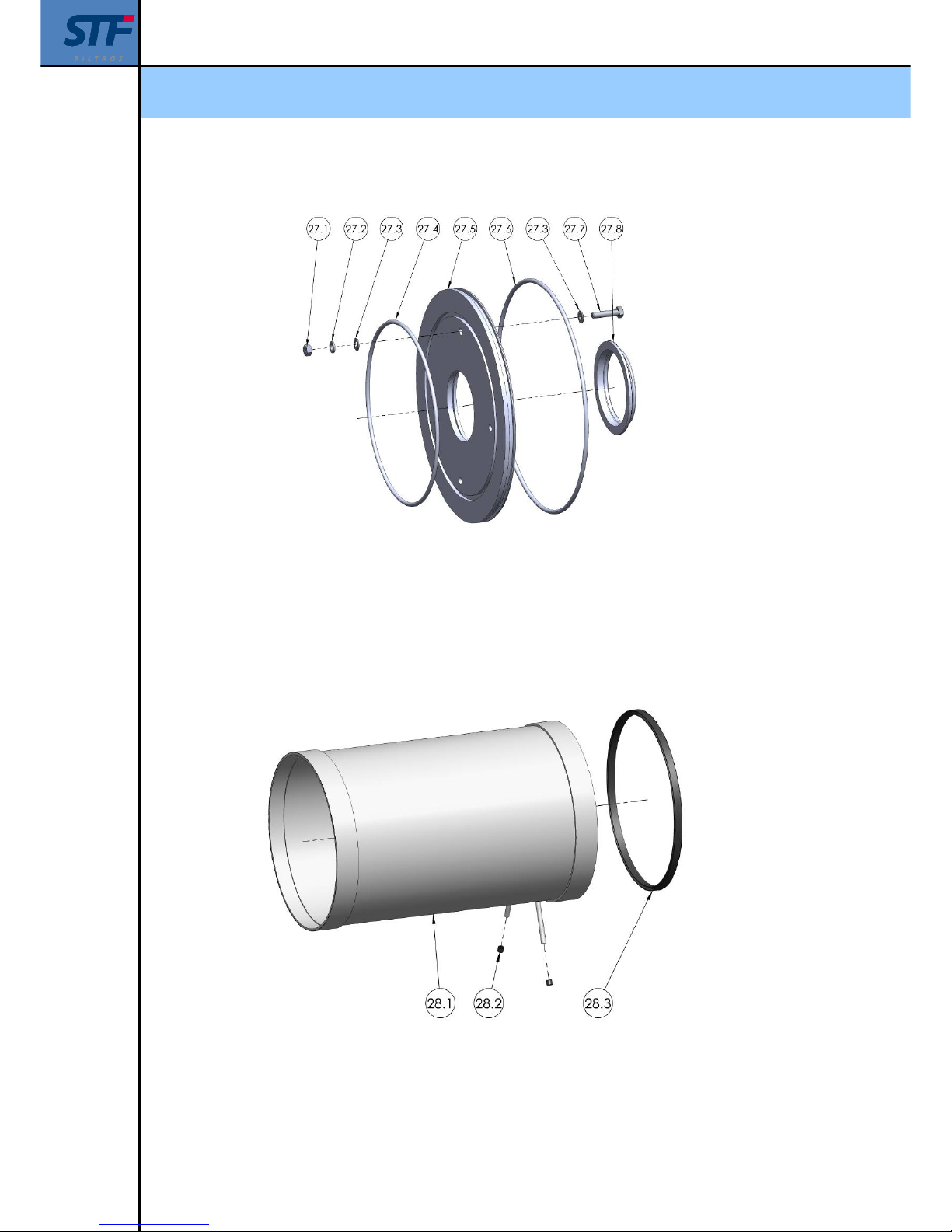
27 RIM WATERTIGHTNESS
27.1 FMA-2003 - 2014 M8 nut 4
27.2 FMA-2003 - 2014 M8 washer 4
27.3 FMA-2003 - 2014 M8 washer 8
27.4 FMA-2003 - 2014 ø230x5 O-ring 1
27.5
FMA-2003 - 2010 Rim watertightness 1
FMA-2012 / 2014 Rim watertightness 1
27.6
FMA-2003 - 2010 ø291,47x5,33 O-ring 1
FMA-2012 / 2014 ø468.76x6,99 O-ring 1
27.7 FMA-2003 - 2014 M8x40 screw 4
27.8 FMA-2003 - 2014 H joint 1
28 WATERTIGHTNESS DISK
28.1
FMA-2003 Prefiltration cartridge 1
FMA-2004 - 2010 Prefiltration cartridge 1
FMA-2012 / 2014 Prefiltration cartridge 1
28.2 FMA-2003 - 2014 Cap GPN-280-ER8 2
28.3
FMA-2003 - 2010 62VA82 joint
FMA-2012 / 2014 62VA82 joint
Page 40
Installation, operation and maintenance manual - FMA 2000
Ref: 2000/CPF01/230/VH 40
Order Equipment model Description Number of units
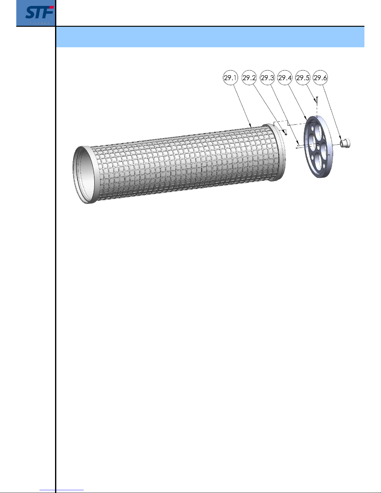
29 FILTRATION CARTRIDGE
29.1
FMA-2003
PVC screen cartridge ….. Micron 1
INOX screen cartridge …. Micron 1
FMA-2004
PVC screen cartridge ….. Micron 1
INOX screen cartridge …. Micron 1
FMA-2006
PVC screen cartridge ….. Micron 1
INOX screen cartridge …. Micron 1
FMA-2008
PVC screen cartridge ….. Micron 1
INOX screen cartridge …. Micron 1
FMA-2010
PVC screen cartridge ….. Micron 1
INOX screen cartridge …. Micron 1
FMA-2012
PVC screen cartridge ….. Micron 1
INOX screen cartridge …. Micron 1
FMA-2014
PVC screen cartridge ….. Micron 1
INOX screen cartridge …. Micron 1
29.2 FMA-2003 - 2014 M6 nut 4
29.3 FMA-2003 - 2014 M6x12 screw 2
29.4
FMA-2003 - 2010 Disc 1
FMA-2012 / 2014 Disc 1
29.5 FMA-2003 - 2014 M 6x35 screw 4
29.6 FMA-2003 - 2014 Housing guide 1
30
FMA-2003 - 2010 ø314x14 O-ring joint 1
FMA-2012 / 2014 ø498x14 O-ring joint 1
Page 41
Installation, operation and maintenance manual - FMA 2000
Ref: 2000/CPF01/230/VH 41
Page 42
Installation, operation and maintenance manual - FMA 2000
Ref: 2000/CPF01/230/VH 42
Page 43
Installation, operation and maintenance manual - FMA 2000
Ref: 2000/CPF01/230/VH 43
Page 44
Installation, operation and maintenance manual - FMA 2000
Ref: 2000/CPF01/230/VH 44
Page 45
Installation, operation and maintenance manual - FMA 2000
Ref: 2000/CPF01/230/VH 45
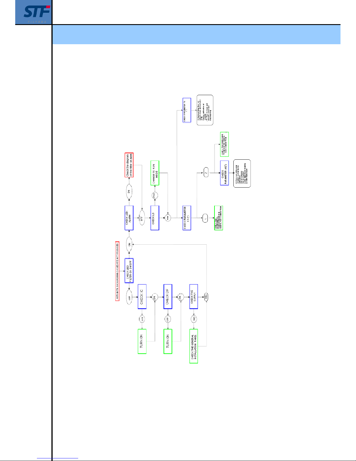
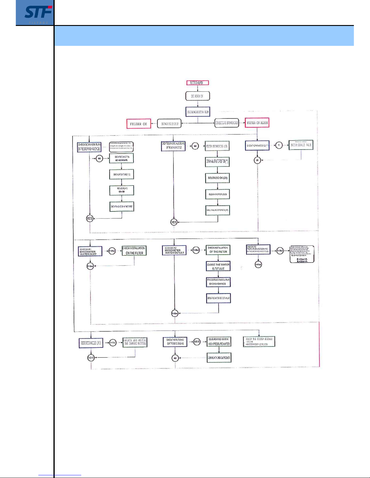
17. – ERROR DETECTION
(*) C1 – Pressure switch selection differential & pressure transducers.
Se programmer panel / Modify parameters.
(**) T8 – Time between backwashings.
See programmer panel / Modify parameters.
Page 46
Installation, operation and maintenance manual - FMA 2000
Ref: 2000/CPF01/230/VH 46
(***) – See hydraulic circuit section.
(****) C2 – Consecutive pieces counter.
See programmer panel section / Modify parameters
Page 47

Installation, operation and maintenance manual - FMA 2000
Ref: 2000/CPF01/230/VH 47
Sistemas de Filtrado y Tratamientos de Fluidos S.A.
Pol. Armentera Parc. 87
22400 Monzón (Huesca / Spain)
Tel: +34 974 401 933
Fax: +34 974 417 809
 Loading...