

STEYR 4 CYLINDER, 6 CYLINDER, MO84K32, MO94K33, MO114K33 Service Manual
...
www.steyr-motors.com
STEYR MOTORS GmbH
Im Stadtgut B1, A-4407 Steyr-Gleink, AUSTRIA
4 CYLINDE RS
+ 6 CYLINDE RS
STEYR MARINE ENGINES
SERVICE MANUAL
P/N Z001019/0 6th Edition July 2008
4 CYLINDE RS
+ 6 CYLINDE RS

THIS PAGE IS INTENTIONALLY BLANK
PREFACE
STEYR MOTORS GmbH
After Sales Service
Im Stadtgut B1
4407 STEYR
AUSTRIA
07252/222/52
07252/222/29
vom Inland:
from home country
+43/7252/222/52
+43/7252/222/29
vom Ausland
from foreign
countries:
service@steyr-motors.com
http://www.steyr-motors.com
STEYR MOTORS GmbH has developed high-performance diesel engines with modulated high-
pressure direct injection, especially for the marine environment. STEYR marine engines are designed to be
adapted to various propulsion systems.
This SERVICE MANUAL is published with the main intention -
to provide information in form of technical data and know-how based on our experience in the marine diesel
engine business, which will enable you in case of possible failure to operate, service and repair the engine
4 & 6 CYLINDER MARINE
ENGINES
to maintain their operating safety and reliability.
To achieve continuous improvement with regard to form and contents of the information required, we are
assigned to your aid.
We, therefore, would much appreciate your comment to the following questions -
- Which descriptions or terms are not understandable?
- Which supplements or completions do you propose ?
- Where did creep in contents-related mistakes ?
Please address your comment to:
Z001019/0_6_July 2008
Z001019/0_6_July 2008
Repair and maintenance works on engine
The descriptions and instructions in this technical documentation should support you in use and repair of our
product. They refer to a specific equipment status of engine componets and accessories. Your individual
engine may be equipped with other or less accessory.
For any component not covered in this manual, please contact STEYR MOTORS GmbH, After Sales Ser-
vice, as to respective documentation.
This manual also contains specific references to your personal safety as user, as well as that of your
customers, their passengers and other persons being close to the engine/boat.
Product specifications, illustrations and technical data
When reference is made in this manual to a brand name, product number, product or specific tool, an
equivalent product may be used in place of the product or tool referred to, unless stated otherwise. To exclude
possible danger, the operator has to provide for adequate safety precautions.
All information, illustrations and specifications in this manual are based on the latest product data available at
the time of printing. It cannot be guaranteed that this manual is constantly updated. Revised versions edited at
a later date will replace all preceding editions.
Illustrations in this manual may not always correspond to actual implements or components and are
mainly intended as reference.
STEYR MOTORS GmbH reserves the right to make changes at any time, without notice, on technical
data or models and/or to discontinue models. The right is also reserved to change technical data or
components at any time, without incurring any obligation to retrofit new parts on models produced
prior to date of such change.
To guarantee proper function of the engine and its attached parts after a repair, correct assembly is of
utmost importance. Such works are to be carried out with greatest care, in accordance with repair
instructions.
WARRANTY: Warranty claims will expire if repair, service and operation of the engine do not
correspond to the guidelines defined by STEYR MOTORS GmbH Please
address your warranty claims, in accordance with warranty regulations, directly to
the After Sales Service of STEYR MOTORS GmbH, Steyr.
Every STEYR dealer is obliged to fill out the warranty registration card enclosed to every sold
STEYR marine engine or every sold boat with a built-in STEYR marine engine.
Part 1 (Warranty Registration Card) is to be handed over to the customer, part 2 (Dealer Record
Card) remains with the dealer and part 3 is to be sent to the After Sales Service of STEYR
MOTORS GmbH.
This warranty registration card serves as a proof of ownership and is to be submitted in case
of warranty claims.
Every STEYR dealer is also obliged to carry out the Installation and pre-delivery inspection log.
One copy (completely filled out) of this Installation and pre-delivery inspection log is to be sent
to the After Sales Service of STEYR MOTORS GmbH.
Z001019/0_6_July 2008
TABLE OF CONTENTS
(MAIN ASSEMBLY GROUP ENGINE)
GENERAL
01 ENGINE
02 COUPLING
03 FUEL SYSTEM
04 EXHAUST SYSTEM
05 COOLING SYSTEM
06 ELECTRICAL EQUIPMENT

Z001019/0_6_July 2008
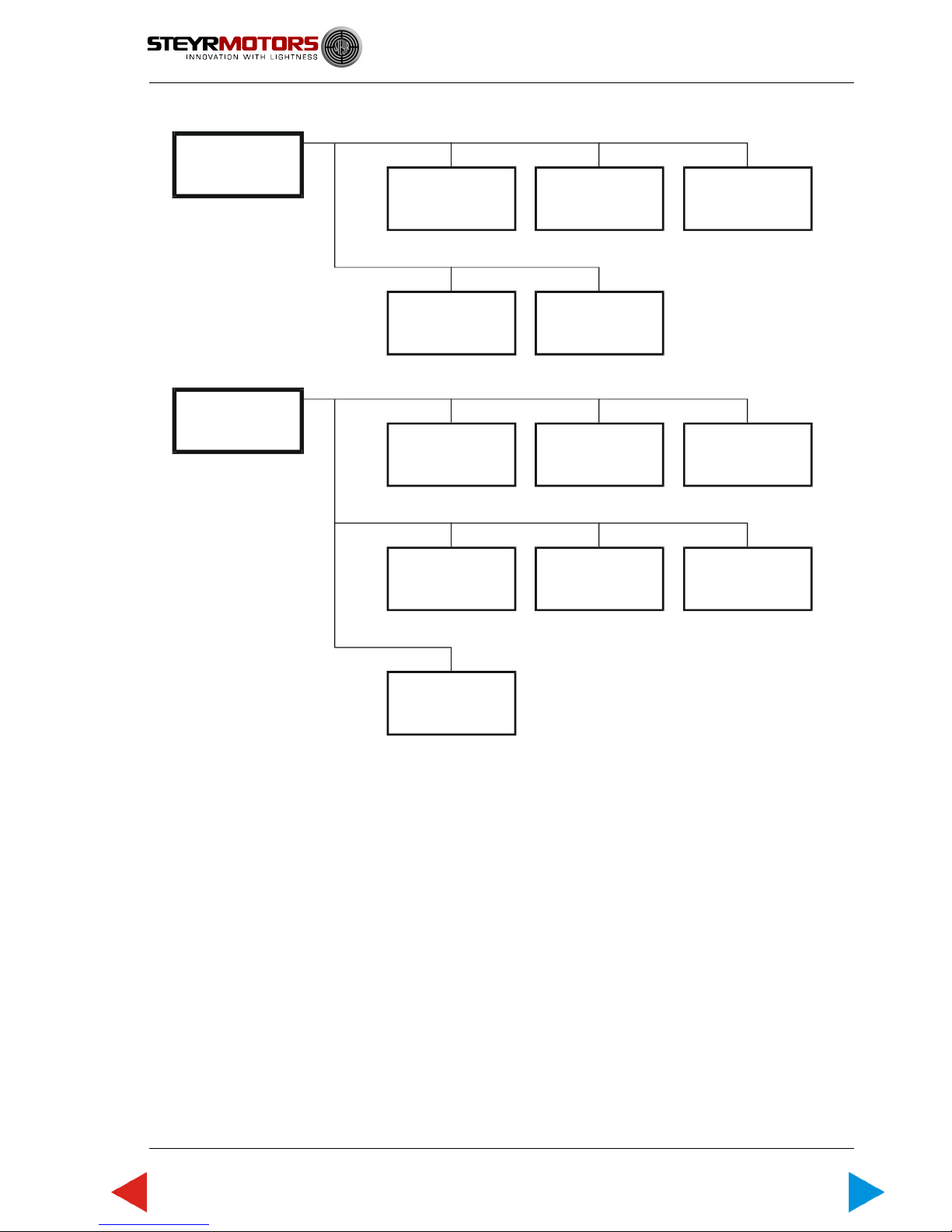
Components
01
Engine
01.00
Engine timing,
engine mount
01.01
Cylinder block
01.02
Chrankshaft
bearing,
vibration damper
01.03
Flywheel,
housing
01.04
Piston,
connection rod
01.05
Chamshaft,
housing,
valve drive
01.06
Engine housing,
oil pump,
oil suction pipe
01.08
Intake manifold,
intercooler
01.13
Engine oil cooler,
01.09
Auxiliary drive-PTO
01.14
Exhaust manifold,
seals,
heat exchanger
02
Coupling
03
Fuel system
04
Exhaust system
02.01
Torsion coupling
02.02
Coupler
02.03
Torsion coupling
Centa
03.02
Fuel pump,
unit injector,
pipes
03.04
Air filter
03.05
Turbo charger
03.08
Control solenoid
03.09
Fuel filter
03.11
Glow plugs
04.01
Hi-riser
Z001019/0_6_July 2008
05
Cooling system
06
Electrical
system
05.01
Cooler,
heat exchanger,
expansions tank
05.03
Pipes,
thermostat
05.04
Coolant pump
05.10
Raw water pump,
side mounted
05.11
Raw water pump,
front mounted
06.01
Generator,
alternator
06.03
Starter motor
06.05
Engine harness
06.06
EMS, E-box,
diagnosis system,
fuses
06.07
Instrument panel,
connecting cable
06.10
Sender, sensor
06.12
Battery,
charge equalization
Z001019/0_6_July 2008
VERSIONS OF MANUAL
Version Date Modification
1.0 01. 10. 2000 new edition
2.0 01. 06. 2002 release typ 164, 246
3.0 01. 07. 2005 release typ 256
4.0 01. 07. 2007 modification
5.0 01. 03. 2008 modification
6.0 01. 07. 2008 modification

Z001019/0_8_Octobre 2011 Page GENERAL-1
GENERAL
SERVICE MANUAL MARINE ENGINES
ToC
GENERAL
Table of Contents
A General Remarks .................................................................................. 3
A 1 Model and Serial Numbers ..................................................................... 3
A 2 Documentation........................................................................................ 4
A 3 Model summary ...................................................................................... 5
A 3.1 Model summary 4 cylinder engines ........................................................ 5
A 3.2 Model summary 6 cylinder engines ........................................................ 8
A 4 Technical Data and Overview ................................................................. 12
A 4.1 T echnical Data and Overview 4 cylinder engines.................................... 12
A 4.2 T echnical Data and Overview 6 cylinder engines.................................... 16
B Specifications ....................................................................................... 20
B 1 Fuel Requirements ................................................................................. 20
B 2 Motor oil .................................................................................................. 21
C Maintenance and Service..................................................................... 22
C 1 Trouble Check Chart............................................................................... 22
C 2 Service- and Maintenance Schedule...................................................... 24
D General Information.............................................................................. 26
D 1 Electronic Engine Management System (ECU)...................................... 26
D 2 Diagnostic System.................................................................................. 27
D 3 Extended Storage Preservation Procedure............................................. 28
D 4 Engine Break-in procedure...................................................................... 32
D 5 Operation after Break-in .......................................................................... 34
E Quality Gudelines for Repair ................................................................ 36
E 1 Spare parts specification ......................................................................... 36
E 2 Workshop profile ..................................................................................... 36
E 3 Nomenclature .......................................................................................... 37
E 4 SI - System .............................................................................................. 38
E 5 Abbreviations .......................................................................................... 39
F Operating material and Information on Disposal................................ 40
F 1 List of operating material ......................................................................... 40
F 2 Disposal of automotive waste products.................................................... 41
G Notes on Safety..................................................................................... 42
G 1 General notes on safety ........................................................................... 42
G 2 Guidelines for damage prevention ........................................................... 42
G 3 Legal rules............................................................................................... 42
G 4 Safety in the use of operating material ..................................................... 43

GENERAL
Page GENERAL-2 Z001019/0_8_Octobre 2011
SERVICE MANUAL MARINE ENGINES
ToC
G 5 Measures in case of accidents ................................................................ 43
H Thightening Torques ............................................................................ 44
H 1 Listing of Thightening Torques.................................................................. 44
H 2 General Tightening torques ...................................................................... 49
H 3 Testing of torque wrench .......................................................................... 50
H 4 Non-destructive material testing ............................................................... 50
H 5 Use of adhesive and sealing materials..................................................... 50
H 6 Solvent-free sealing materials.................................................................. 50
J Wear Limits............................................................................................ 52
J 1 Adjustment information for service and maintenance ................................ 53
Z001019/0_8_Octobre 2011 Page GENERAL-3
GENERAL
SERVICE MANUAL MARINE ENGINES
ToC
A GENERAL REMARKS
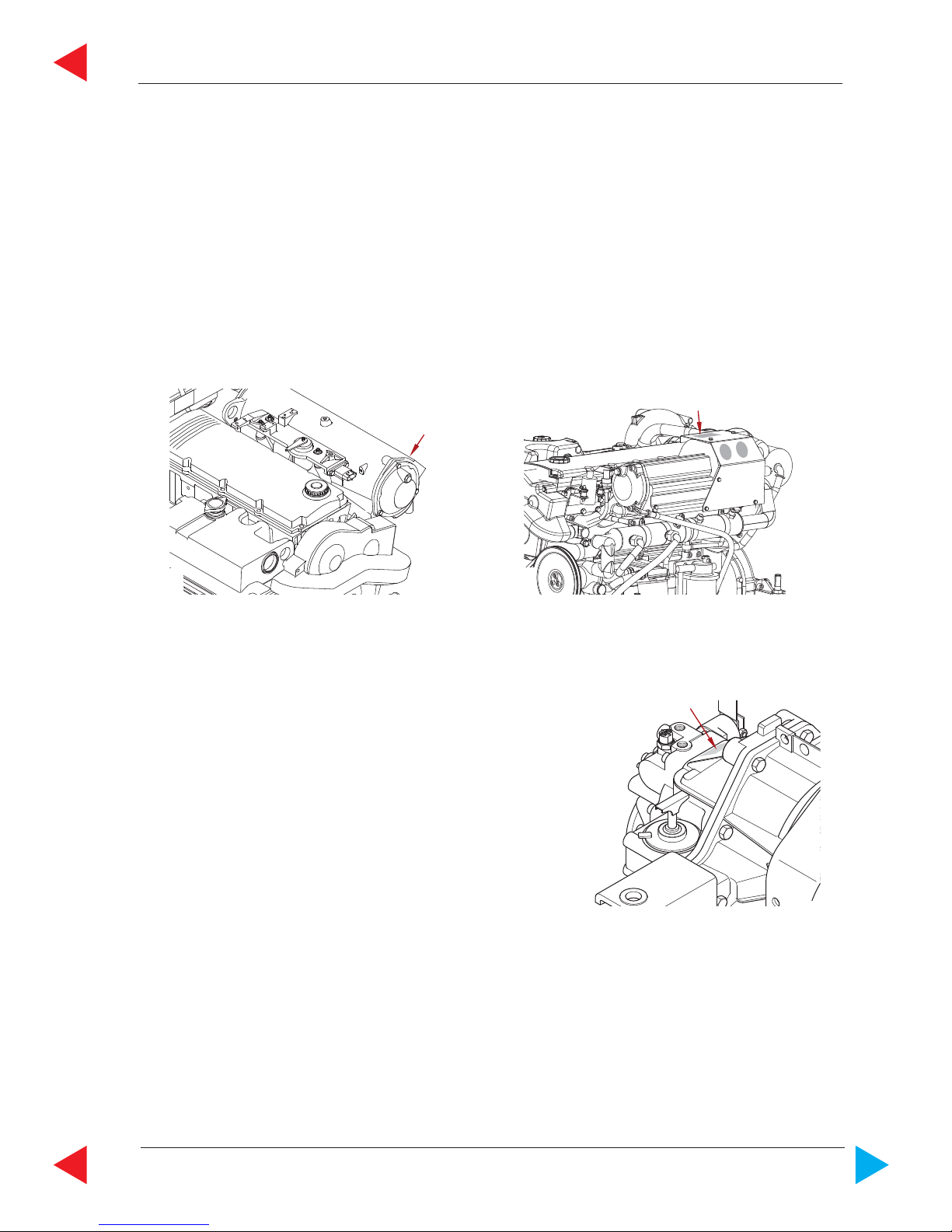
A 1 Model and Serial Numbers
01.01 ill.1
01.01 ill.3
01.01 ill.2
FOR ALL
4 CYL. MARINE ENGINES
The primary model and serial number (ill.1 or ill.2) is
located on the engine as illustrated.
These numbers are required for warranty
claims and ordering parts.
The model and serial number of the marine gearbox
is located on the marine gearbox housing as illustrated.
To obtain instructions regarding marine gearbox
operation, refer to marine gearbox owners manual.
17
06014
08006
1
1
08007
FOR ALL
6 CYL. MARINE ENGINES
GENERAL
Page GENERAL-4 Z001019/0_8_Octobre 2011
SERVICE MANUAL MARINE ENGINES
ToC
The following documentation is available in English language on our website:
http://www.steyr-motors.com/technical
technical documentation on CD - ROM P/N Z 001009/0
operation-, maintenance & warranty manual
for all marine engines P/N Z 001022/0
tool catalogue for all marine engines P/N Z 001002/1
spare parts catalogue STEYR 94 td diesel marine P/N Z 001023/0
STEYR 144 vti/td diesel marine P/N Z 001005/0
STEYR 164 td diesel marine P/N Z 001015/0
STEYR 174 vti diesel marine P/N Z 001011/0
STEYR 166 td diesel marine P/N Z 011796/1
STEYR 236 FDE P/N Z 011796/0
STEYR 236 td diesel marine P/N Z 011796/1 - Z011769/2
STEYR 246 td diesel marine P/N Z 011800/0
STEYR 256 td diesel marine P/N Z 011810/0
STEYR 266 td diesel marine P/N Z 011805/0
installation manual for marine engines P/N Z 001007/0
service manual for all marine engines P/N Z 001019/0
operator's manual marine gear ZF P/N Z 001003/0
Diagrams marine engine functions on CD P/N Z 001021/0
A 2 Documentation 4 and 6 cylinder
Z001019/0_8_Octobre 2011 Page GENERAL-5
GENERAL
SERVICE MANUAL MARINE ENGINES
ToC
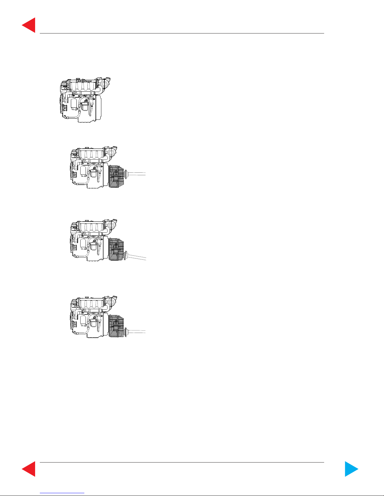
A 3 Modell summary
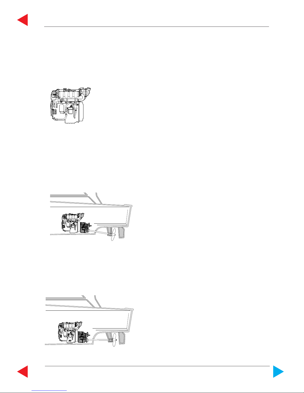
A 3.1 Modell summary 4 cylinder engines
03.01 ill.1
03.01 ill.2
03.01 ill.3
Inborder i.e. ZF 45 Marinegear
Down angle
Bobtail - Version
Innenborder i.e. ZF 63 Marinegear
Equipment:
with side mounted raw water
pump or,
with side mounted raw water
pump, power steering pump
GENERAL
Page GENERAL-6 Z001019/0_8_Octobre 2011
SERVICE MANUAL MARINE ENGINES
ToC
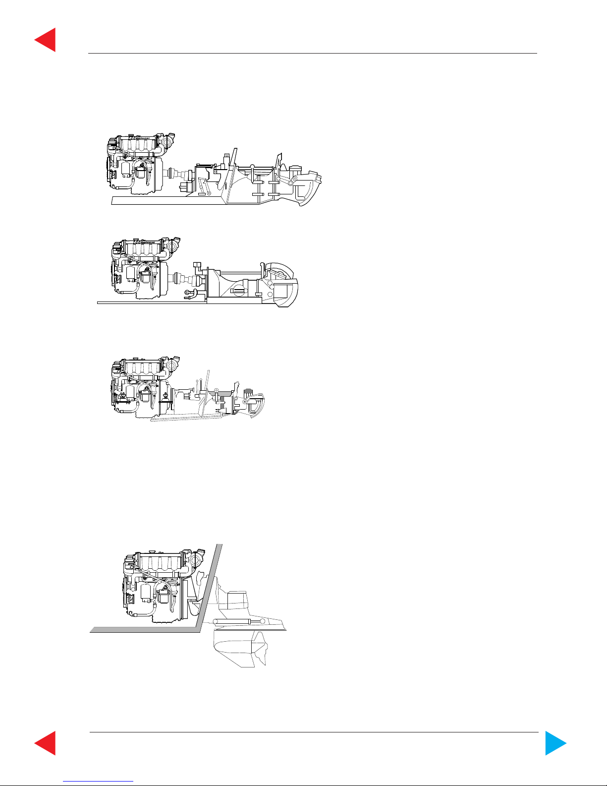
03.01 ill.4
03.01 ill.5
03.01 ill.6
Equipment
Bobtail "B"
Direkt gearbox
A-down angle gear box
Parallel offset gearbox
Lifeboat Engine
03.01 ill.7
Z001019/0_8_Octobre 2011 Page GENERAL-7
GENERAL
SERVICE MANUAL MARINE ENGINES
ToC
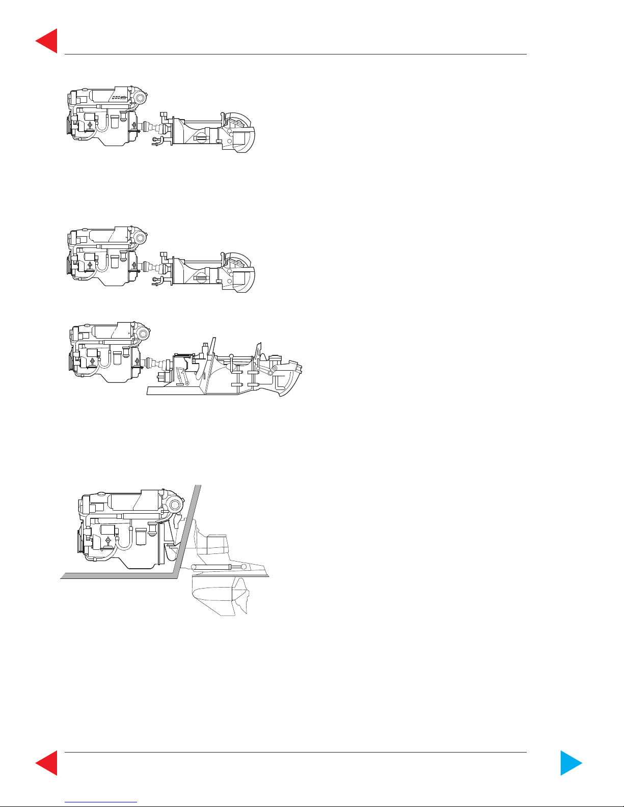
Stern Drive
Jet Drive
03.01 ill.10
03.01 ill.11
TYPE
Mercury Alpha Bravo I, II & III
Volvo DP 290
Volvo DP 290 Hydraulic
SX - Stern Drive
TYPE
Alamarin
Hamilton
Castoldi
03.01 ill.8
03.01 ill.9
GENERAL
Page GENERAL-8 Z001019/0_8_Octobre 2011
SERVICE MANUAL MARINE ENGINES
ToC
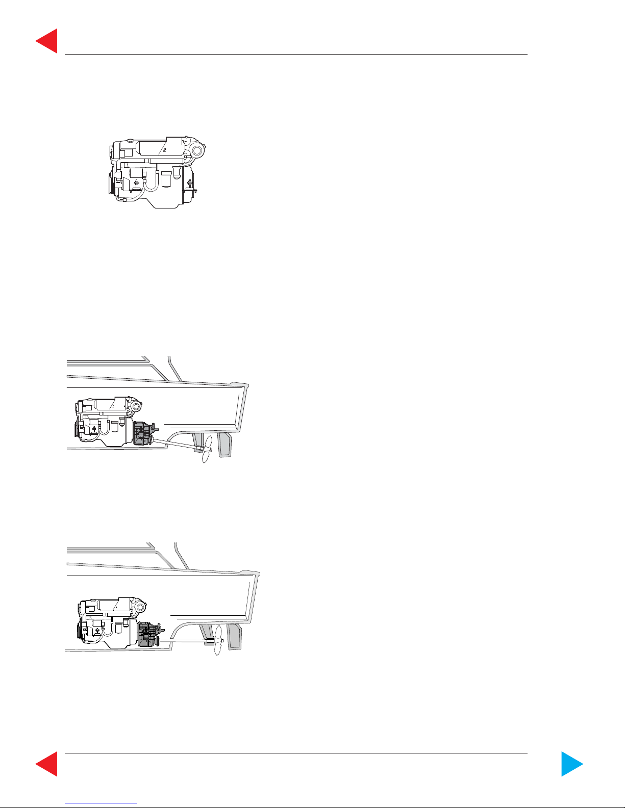
A 3.2 Modell summary 6 cylinder engines
03.02 ill.1
03.02 ill.2
03.02 ill.3
Inborder i.e. ZF 63 Marine gear
Down angle
with side mounted raw water
pump or,
with side mounted raw water
pump, power steering pump
and front mounted auxiliary
drive-PTO
Bobtail - Version

Z001019/0_8_Octobre 2011 Page GENERAL-9
GENERAL
SERVICE MANUAL MARINE ENGINES
ToC
03.02 ill.4
03.02 ill.5
03.02 ill.6
03.02 ill.7
03.02 ill.8
Transmission
Lifeboat Engine
Equipment
Bobtail "B"
Direkt gearbox
A-down angle gear box
Parallel offset gearbox
i = 2.5V, shaft angle 12°
i = 2.0V, shaft angle 12°
GENERAL
Page GENERAL-10 Z001019/0_8_Octobre 2011
SERVICE MANUAL MARINE ENGINES
ToC
03.02 ill.9
03.02 ill.10
03.02 ill.12
Stern drive
Mercury Bravo II & III
Volvo DP 290
Stern Power Drive
Volvo DP 290 ZF
Hydraulic Pump
Volvo SX - Drive
King Cobra Drive
Type
Jet Drive
TYPE
Alamarin
Hamilton
Castoldi
Jet drive
03.02 ill.11

Z001019/0_8_Octobre 2011 Page GENERAL-11
GENERAL
SERVICE MANUAL MARINE ENGINES
ToC
THIS PAGE IS INTENTIONALLY BLANK
GENERAL
Page GENERAL-12 Z001019/0_8_Octobre 2011
SERVICE MANUAL MARINE ENGINES
ToC
A 4.1 Technical data and overview 4 cylinder engines
MAKE STEYR M 14 TCM, TCAM
type MO84K32 MO94K33 MO114K33 MO144V38
displacement 2133 cm³
piston displacement 85,0 x 94,0 mm
number of cylinders 4-cylinder in-line engine (position of cyl. 1 at vibration damper side)
ignition order 1 - 3 - 4 - 2
sense of rotation, seen from front right
compression ratio 17,5 : 1
full-load speed range (rpm) 3000 - 3200 3050 - 3800 3200 - 3800 3600 - 3800
idle speed 650 rpm. (adjustable)
injection pump - nozzle with modelling needle control
and electronic control
fuel acc. to CEC RF-03-A-84 (DIN EN 590) Cetan >49; diesel fuel
No. 2-D, temperature above -7°C; No.1-D, temperature below -7°C
fuel filter P/No. 2203710/0
fuel filter location intake-sided
air filter P/No. 2178992/0
oil pressure above 2000 rpm. 400 - 700 kPa (60 - 100 PSI) microprocessor controlled
filling capacity motor oil approx. 8,0 l engine housing (incl. approx. 1 l oil filter contents)
specification motor oil SAE 5W-50/ACEA B4-02/API CF or 10W-40/ACEA, E4, E5, E7,
API CF / P/N0. Z010058/0
oil and oil filter change intervals*) every 150 operating hours and/or once per season
oil filter P/No. 2178582/1
oil filter location pressure-sided
electric charging system 14 V / 90 A alternator with transistorized voltage regulator
cooling system dual cooling circuit; thermostat-controlled, pressurized cooling
circuit; circulating pump with heat exchanger on engine; governor
pump, external raw water circuit to heat exchanger
coolant capacity 11,5 liters
coolant STEYR MOTORS engine coolant - 36 C°
P/No. Z011785/0
*) extended periods to be evaluated upon application and type of usage
STEYR MOTORS GmbH. reserves the right to make changes without notice or obligations.
**) Efficiency of gearbox = 97,0%, efficiency of Z-drive = 95,5%
rated power acc. EN ISO 8665:2006
(impeller **) KW / HP
Jet - Drive / Inboard
Z - Drive
53 / 71
52 / 70
64 / 86
63 / 84
78 / 105
77 / 104
103 / 138
101 / 136
Z001019/0_8_Octobre 2011 Page GENERAL-13
GENERAL
SERVICE MANUAL MARINE ENGINES
ToC
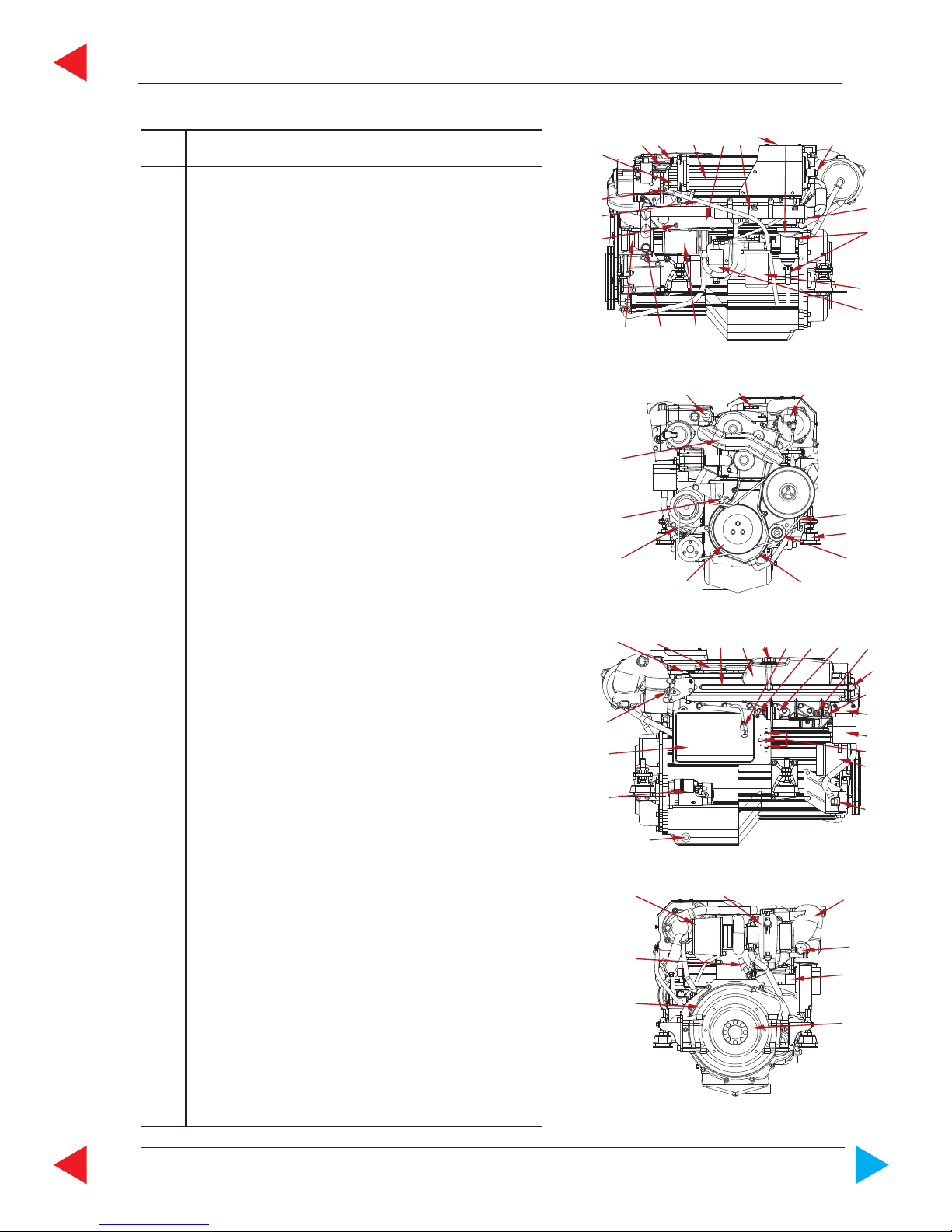
Overview for all STEYR 4 Cyl. Marine Engines
06001
19
18
17
16
15
14
13
12
11
15
1
4
7
8
23
6
10 9
06002
31
30
22
23
24
21
25
26
27
20
29
28
38
06003
44
43
136
15
34
40
41
1
3932 33
37
42
35
06004
45
52
51
50
46
47
48
49
Item Designation
1 Zinc Anode (4 Units)
2 Model and Serial Number
3 Intercooler
4 Fuel/Oil Cooler with Raw Water Drain Plug
5 Fuel Pump
6 Oil Seperator
7 Raw Water Drain Plug
8 Valve Crankshaft Housing Ventilation
(only SOLAS)
9 Oil Drain Plug
10 Fuel Filter
11 Oil Filter
12 Hydraulic Pump
13 Raw Water Inlet Fitting
14 Raw Water Pump
15 Coolant Drain Plug (2 Units)
16 Engine Oilcooler
17 Oil Suction Pipe
18 Oil Dipstick
19 Hydraulic Oil Tank
20 Cooler Cap
21 Potentiometer Accelerator
22 Motor Oil Filler Cap
23 Boost Pressure Sensor
24 Rack Position Sensor *)
25 Drive Belt
26 Cover T-Belt, Lower
27 Engine Mount
28 Drive Belt Tensioner
29 Vibration Damper
30 Cover T-Belt, Upper
31 Engine Lifting Eye
32 Speed Sensor
33 Valve Cover
34 Heat Exchanger
35 Coolant Expansion Tank
36 Diagnostic Outlet
37 Inversion Switch (only for SOLAS)
38 Connector Instrument Panel
39 Coolant Temperature Sensor
40 Thermostat Housing
41 Alternator
42 Circuit Breakers
43 Engine Management System/Fuses
44 Exhaust Temperature Sensor
45 Air Filter
46 Turbo Charger
47 Exhaust Elbow
48 Starter Relais (Backside E-Box Ground Plate)
49 Starter Motor
50 Flywheel
51 Flywheel Housing
52 Oil Pressure Sensor
*) This sensor is magnetism sensitive. All external magnets must be kept away.
GENERAL
Page GENERAL-14 Z001019/0_8_Octobre 2011
SERVICE MANUAL MARINE ENGINES
ToC
MAKE STEYR M 14 TCAM
type MO144M38 MO164M40
displacement 2133 cm³
piston displacement 85,0 x 94,0 mm
number of cylinders 4-cylinder in-line engine (position of cyl. 1 at vibration damper side)
ignition order 1 - 3 - 4 - 2
sense of rotation, seen from front right
compression ratio 17,5 : 1
full-load speed range (rpm) 3700 - 3900 3800 - 4000
idle speed 650 rpm. (adjustable)
injection pump - nozzle with modelling needle control
and electronic control
fuel acc. to CEC RF-03-A-84 (DIN EN 590) Cetan >49; diesel fuel
No. 2-D, temperature above -7°C; No.1-D, temperature below -7°C
fuel filter P/No. 2203710/0
fuel filter location intake-sided
air filter P/No. 2178992/0
oil pressure above 2000 rpm. 400 - 700 kPa (60 - 100 PSI) microprocessor controlled
filling capacity motor oil approx. 8,0 l engine housing (incl. approx. 1 l oil filter contents)
specification motor oil SAE 5W-50/ACEA B4-02/API CF or 10W-40/ACEA, E4, E5, E7,
API CF / P/N0. Z010058/0
oil and oil filter change intervals*) every 150 operating hours and/or once per season
oil filter P/No. 2178582/1
oil filter location pressure-sided
electric charging system 14 V / 90 A alternator with transistorized voltage regulator
cooling system dual cooling circuit; thermostat-controlled, pressurized cooling
circuit; circulating pump with heat exchanger on engine; governor
pump, external raw water circuit to heat exchanger
coolant capacity 11,5 liters
coolant STEYR MOTORS engine coolant - 36 C°
P/No. Z011785/0
*) extended periods to be evaluated upon application and type of usage
STEYR MOTORS GmbH. reserves the right to make changes without notice or obligations.
**) Efficiency of gearbox = 97,0%, efficiency of Z-drive = 95,5%
rated power acc. EN ISO 8665:2006
(impeller **) KW / HP
Jet - Drive / Inboard
Z - Drive
103 / 138
101 / 136
116 / 156
114 / 154

Z001019/0_8_Octobre 2011 Page GENERAL-15
GENERAL
SERVICE MANUAL MARINE ENGINES
ToC
Overview for all STEYR 4 Cyl. Marine Engines
06001
19
18
17
16
15
14
13
12
11
15
1
4
7
8
23
6
10 9
06002
31
30
22
23
24
21
25
26
27
20
29
28
38
06003
44
43
136
15
34
40
41
1
3932 33
37
42
35
06004
45
52
51
50
46
47
48
49
Item Designation
1 Zinc Anode (4 Units)
2 Model and Serial Number
3 Intercooler
4 Fuel/Oil Cooler with Raw Water Drain Plug
5 Fuel Pump
6 Oil Seperator
7 Raw Water Drain Plug
8 Valve Crankshaft Housing Ventilation
(only SOLAS)
9 Oil Drain Plug
10 Fuel Filter
11 Oil Filter
12 Hydraulic Pump
13 Raw Water Inlet Fitting
14 Raw Water Pump
15 Coolant Drain Plug (2 Units)
16 Engine Oilcooler
17 Oil Suction Pipe
18 Oil Dipstick
19 Hydraulic Oil Tank
20 Cooler Cap
21 Potentiometer Accelerator
22 Motor Oil Filler Cap
23 Boost Pressure Sensor
24 Rack Position Sensor *)
25 Drive Belt
26 Cover T-Belt, Lower
27 Engine Mount
28 Drive Belt Tensioner
29 Vibration Damper
30 Cover T-Belt, Upper
31 Engine Lifting Eye
32 Speed Sensor
33 Valve Cover
34 Heat Exchanger
35 Coolant Expansion Tank
36 Diagnostic Outlet
37 Inversion Switch (only for SOLAS)
38 Connector Instrument Panel
39 Coolant Temperature Sensor
40 Thermostat Housing
41 Alternator
42 Circuit Breakers
43 Engine Management System/Fuses
44 Exhaust Temperature Sensor
45 Air Filter
46 Turbo Charger
47 Exhaust Elbow
48 Starter Relais (Backside E-Box Ground Plate)
49 Starter Motor
50 Flywheel
51 Flywheel Housing
52 Oil Pressure Sensor
*) This sensor is magnetism sensitive. All external magnets must be kept away.
GENERAL
Page GENERAL-16 Z001019/0_8_Octobre 2011
SERVICE MANUAL MARINE ENGINES
ToC
A 4.2 Technical data and overview 6 cylinder engines
MAKE STEYR M 16 TCM, TCAM
type MO126M28 MO166K28 MO196K35 MO236K42
displacement 3200 cm³
piston displacement 85,0 x 94,0 mm
number of cylinders 6-cylinder in-line engine (position of cyl. 1 at vibration damper side)
ignition order 1 - 5 - 3 - 6 -2 - 4
sense of rotation, seen from front right
compression ratio 17,5 : 1
full-load speed range (rpm) 2600 - 2800 2600 - 2800 3300 - 3500 4000 - 4300
idle speed 630 rpm. (adjustable)
injection pump - nozzle with modelling needle control
and electronic control
fuel acc. to CEC RF-03-A-84 (DIN EN 590) Cetan >49; diesel fuel
No. 2-D, temperature above -7°C; No.1-D, temperature below -7°C
fuel filter P/No. 2177745/1
fuel filter location suction-sided
air filter MO126 - P/No. 2178992/0; all other 6 Cyl. - P/N 2178992/1
oil pressure above 2000 rpm. 400 - 700 kPa (60 - 100 PSI) microprocessor controlled
filling capacity motor oil approx. 10,0 l engine housing (incl. approx. 1 l oil filter contents)
specification motor oil SAE 5W-50/ACEA B4-02/API CF or 10W-40/ACEA, E4, E5, E7,
API CF / P/N0. Z010058/0
oil and oil filter change intervals*) every 150 operating hours and/or once per season
oil filter P/No. 2178582/1
oil filter location suction-sided
electric charging system 14 V / 90 A alternator with transistorized voltage regulator
cooling system dual cooling circuit; thermostat-controlled, pressurized cooling
circuit; circulating pump with heat exchanger on engine; governor
pump, external raw water circuit to heat exchanger
coolant capacity 13,2 liters
coolant STEYR MOTORS engine coolant - 36 C°
P/No. Z011785/0
*) extended periods to be evaluated upon application and type of usage
STEYR MOTORS GmbH. reserves the right to make changes without notice or obligations.
**) Efficiency of gearbox = 97,0%, efficiency of Z-drive = 95,5%
rated power acc. EN ISO 8665:2006
(impeller **) KW / HP
Jet - Drive / Inboard
Z - Drive
87 / 117
86 / 115
116 / 156
115 / 154
136 / 182
134 / 179
165 / 221
162 / 218
Z001019/0_8_Octobre 2011 Page GENERAL-17
GENERAL
SERVICE MANUAL MARINE ENGINES
ToC
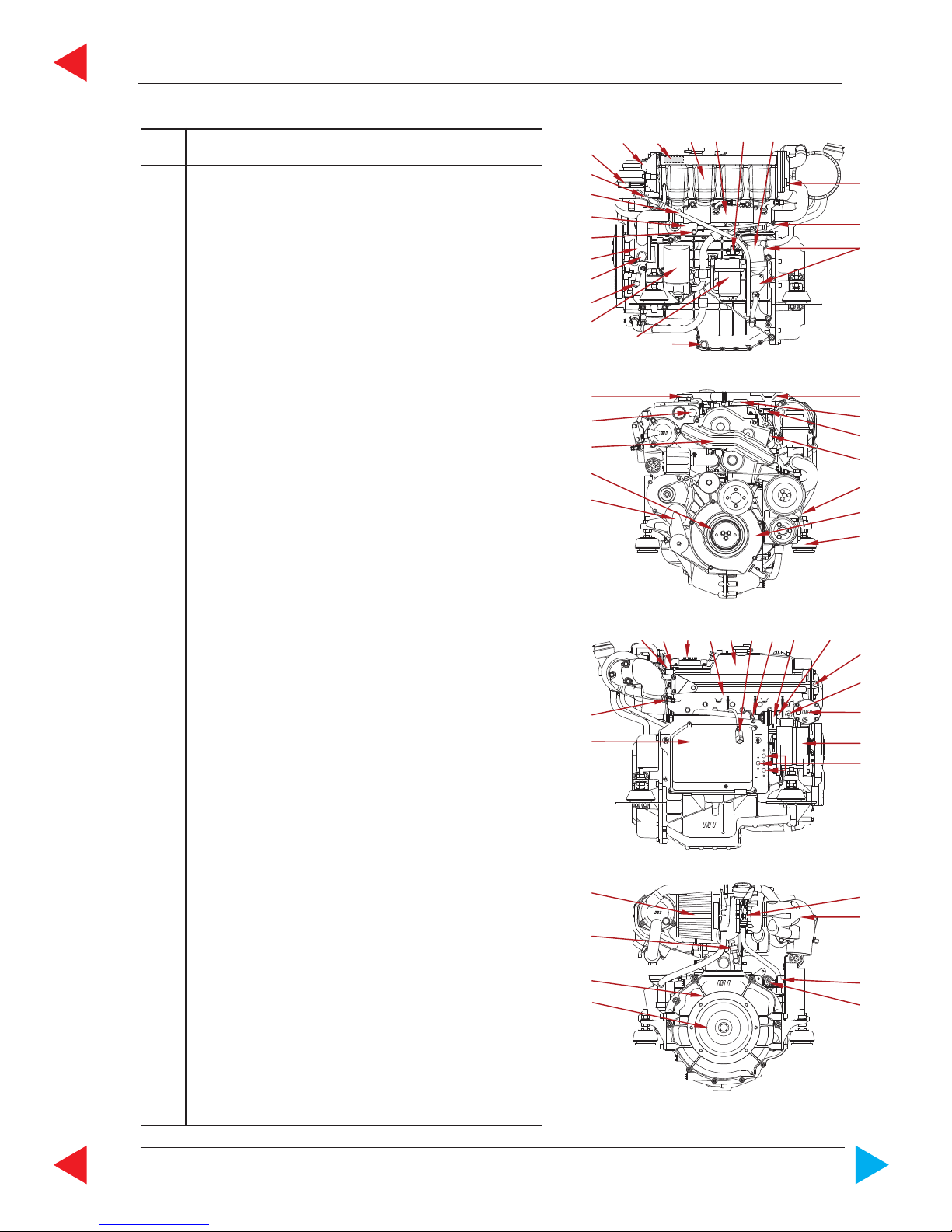
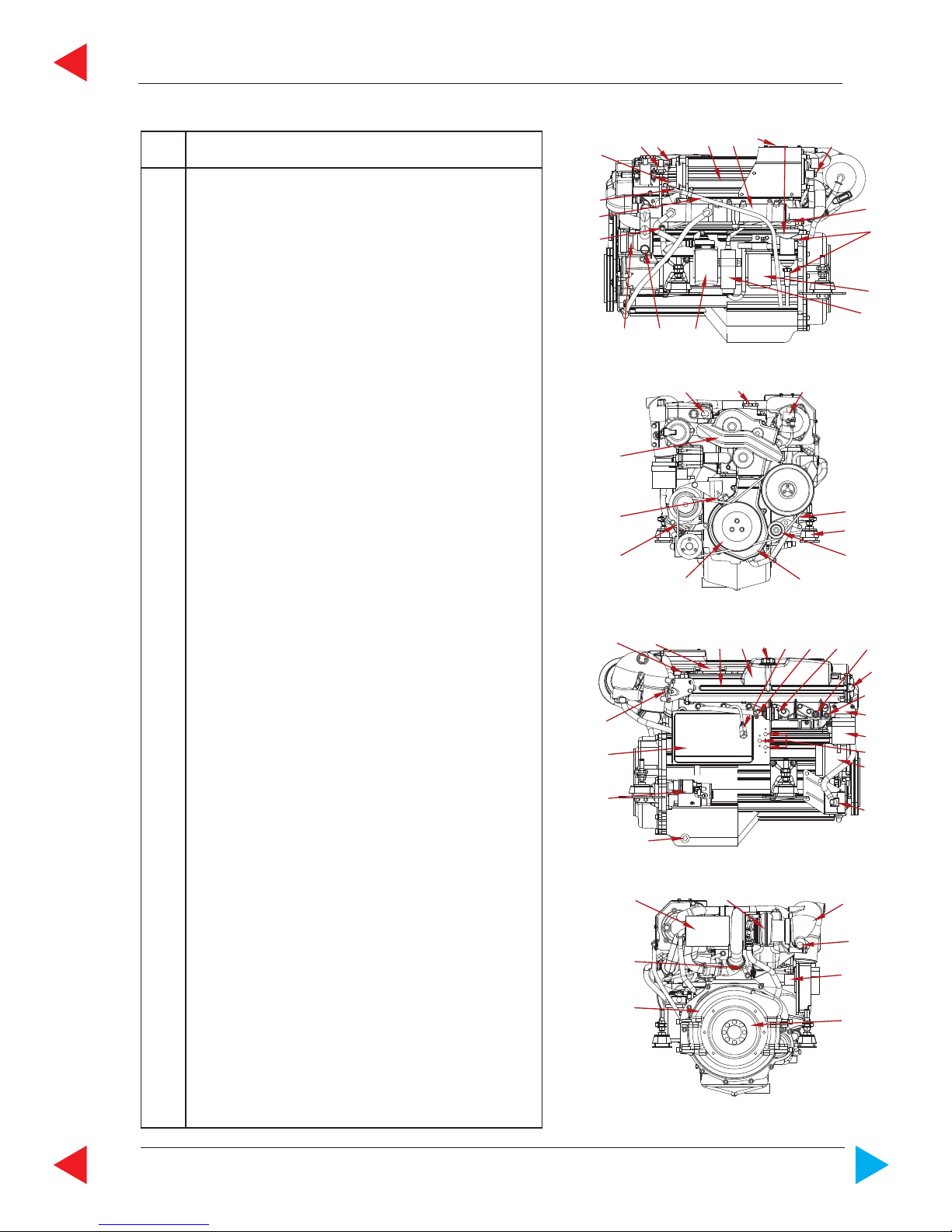
Overview STEYR MO126M28, MO166K28, MO196K35, MO236K42
06032
1423
6 7
2
8
9
10
11
121314
15
16
17
18
5
06033
19 20 21
22
23
24
2526
27
28
29
06034
2 30 31 32 33 34 35
36 37
2
15
38
39
40
41
42
43
44
45
46
06035
47 48
49
2
50
51
52
53
Item Designation
1 Boost Pressure Sensor
2 Zinc Anode (5 Units)
3 Intercooler
4 Fuel- / Hydr. Oil Cooler
5 Engine Oilcooler
6 Model and Serial Number
7 Oil Seperator
8 Raw Water Drain Plug
9 Valve Crankshaft Housing Ventilation
(only SOLAS)
10 Fuel Filter
11 Fuel Pump
12 Oil Filter
13 Raw Water Inlet Fitting
14 Raw Water Pump
15 Coolant Drain Plug (2 Units)
16 Oil Suction Pipe
17 Oil Dipstick
18 Rack Position Sensor *)
19 Engine Lifting Eye
20 Motor Oil Filler Cap
21 Potentiometer Accelerator
22 Drive Belt, Raw Water Pump
23 Engine Mount
24 Drive Belt Tensioner
25 Cover T-Belt, Lower
26 Vibration Damper
27 Drive Belt, Alternator & Hydr: Pump
28 Speed Sensor
29 Cover T-Belt, Upper
30 Valve Cover
31 Heat Exchanger
32 Coolant Expansion Tank
33 Cooler Cap
34 Diagnostic Outlet
35 Inversion Switch (only for SOLAS)
36 Connector Instrument Panel
37 Coolant Temperature Sensor
38 Thermostat Housing
39 Hydraulic Oil Tank
40 Circuit Breakers
41 Alternator
42 Hydraulic Pump
43 Oil Drain Plug
44 Starter Motor
45 Engine Management System/Fuses
46 Exhaust Temperature Sensor
47 Air Filter
48 Turbo Charger
49 Exhaust Elbow
50 Starter Relais (Backside E-Box Ground Plate)
51 Flywheel
52 Flywheel Housing
53 Oil Pressure Sensor
*) This sensor is magnetism sensitive. All external magnets must be kept away.
GENERAL
Page GENERAL-18 Z001019/0_8_Octobre 2011
SERVICE MANUAL MARINE ENGINES
ToC
MAKE STEYR M 16 TCAM
type MO256K43 MO256H45
displacement 3200 cm³
piston displacement 85,0 x 94,0 mm
number of cylinders 6-cylinder in-line engine (position of cyl. 1 at vibration damper side)
ignition order 1 - 5 - 3 - 6 -2 - 4
sense of rotation, seen from front right
compression ratio 17,5 : 1
full-load speed range (rpm) 4000 - 4300 4000 - 4500
idle speed 630 rpm. (adjustable)
injection pump - nozzle with modelling needle control
and electronic control
fuel acc. to CEC RF-03-A-84 (DIN EN 590) Cetan >49; diesel fuel
No. 2-D, temperature above -7°C; No.1-D, temperature below -7°C
fuel filter P/No. 2178992/1
fuel filter location suction-sided
air filter P/No. 2178992/0 P/No.2178992/1
oil pressure above 2000 rpm. 400 - 700 kPa (60 - 100 PSI) microprocessor controlled
filling capacity motor oil approx. 10,0 l engine housing (incl. approx. 1 l oil filter contents)
specification motor oil SAE 5W-50/ACEA B4-02/API CF or 10W-40/ACEA, E4, E5, E7,
API CF / P/N0. Z010058/0
oil and oil filter change intervals*) every 150 operating hours and/or once per season
oil filter P/No. 2178582/1
oil filter location suction-sided
electric charging system 14 V / 90 A alternator with transistorized voltage regulator
cooling system dual cooling circuit; thermostat-controlled, pressurized cooling
circuit; circulating pump with heat exchanger on engine; governor
pump, external raw water circuit to heat exchanger
coolant capacity 13,2 liters
coolant STEYR MOTORS engine coolant - 36 C°
P/No. Z011785/0
*) extended periods to be evaluated upon application and type of usage
STEYR MOTORS GmbH. reserves the right to make changes without notice or obligations.
**) Efficiency of gearbox = 97,0%, efficiency of Z-drive = 95,5%
rated power acc. EN ISO 8665:2006
(impeller **) KW / HP
Jet - Drive / Inboard
Z - Drive
178 / 239
176 / 236
178 / 239
176 / 236
Z001019/0_8_Octobre 2011 Page GENERAL-19
GENERAL
SERVICE MANUAL MARINE ENGINES
ToC
Overview STEYR MO256K43, MO256H45
06028
1423
5 6
2
7
8
9
10
111213
14
15
16
17
06029
18 19 20
21
22
23
2425
26
27
28
06030
2 29 30 31 32 33 34
35 36
2
14
37
38
39
40
41
42
43
44
45
06031
46 47
48
2
49
50
51
52
Item Designation
1 Boost Pressure Sensor
2 Zinc Anode (5 Units)
3 Intercooler
4 Engine Oil / Fuel / Hydr. Oil Cooler
5 Model and Serial Number
6 Oil Seperator
7 Raw Water Drain Plug
8 Valve Crankshaft Housing Ventilation (only
SOLAS)
9 Fuel Filter
10 Fuel Pump
11 Oil Filter
12 Raw Water Inlet Fitting
13 Raw Water Pump
14 Coolant Drain Plug (2 Units)
15 Oil Suction Pipe
16 Oil Dipstick
17 Rack Position Sensor *)
18 Engine Lifting Eye
19 Motor Oil Filler Cap
20 Potentiometer Accelerator
21 Drive Belt, Raw Water Pump
22 Engine Mount
23 Drive Belt Tensioner
24 Cover T-Belt, Lower
25 Vibration Damper
26 Drive Belt, Alternator & Hydr: Pump
27 Speed Sensor
28 Cover T-Belt, Upper
29 Valve Cover
30 Heat Exchanger
31 Coolant Expansion Tank
32 Cooler Cap
33 Diagnostic Outlet
34 Inversion Switch (only for SOLAS)
35 Connector Instrument Panel
36 Coolant Temperature Sensor
37 Thermostat Housing
38 Hydraulic Oil Tank
39 Circuit Breakers
40 Alternator
41 Hydraulic Pump
42 Oil Drain Plug
43 Starter Motor
44 Engine Management System/Fuses
45 Exhaust Temperature Sensor
46 Air Filter
47 Turbo Charger
48 Exhaust Elbow
49 Starter Relais (Backside E-Box Ground Plate)
50 Flywheel
51 Flywheel Housing
52 Oil Pressure Sensor
*) This sensor is magnetism sensitive. All external magnets must be kept away.
GENERAL
Page GENERAL-20 Z001019/0_8_Octobre 2011
SERVICE MANUAL MARINE ENGINES
ToC
B Specifications
B 1 Fuel Requirements
The STEYR Marine Engines are designed for maximum fuel economy. To maintain optimum performance use
diesel fuel according to CEC RF-03-A-84 or equivalent to meet this specification. When temperatures are below
-7° C (20° F), use diesel fuels with additives for low temperature operation.
How to Select Fuel Oil
Fuel quality is an important factor in obtaining satisfactory engine performance, long engine life, and acceptable
exhaust emission levels. Direct injected diesel engines are designed to operate on most diesel fuels marketed
today. In general, fuels meeting the properties of CEC RF-03-A-84 have provided satisfactory performance.
The ASTM D 975 specification, however, does not in itself adequately define the fuel characteristics needed for
assurance of fuel quality. The properties listed in the following fuel oil selection chart have provided optimum engine
performance.
Fuel Oil Selection Chart
ASTM -
T est procedure
D 613 (D 976)
D 1298
D86
D 93
EN 116 (CEN)
D 445
D 1266/D 2622
D 2785
D 130
D 189
D 482
D 95/D 1744
D 974
D 2274
General
Fuel classification
Cetane number
Gravity at 15°C (kg/l)
Destillation
50%
90%
End point
Flash point
CFPP (Cloud point)
Viscosity Kinematic 40°C
Sulfur content
Cupper corrosion
Carbon residue
Conradson number (10% residue)
Ash
Water content
Acid content (strong acid)
Oxidation stability
CEC RF-03-A-84
Limit value and
units
min. 49 - max. 53
min. 0,835
max. 0845
min. 245°C
min. 320°C
max. 340°C
max. 370°C
min. 55°C
min. -- / max. -5°c
min. 2,5 mm²/s
max. 3,5 mm²/s
max. 0,3 mass-%
max. 1
max. 0,2 mass-%
max. 0,01 mass-%
max. 0,05 mass-%
max. 0,20 mg KOH/g
max.2,5 mg/100ml
CEC RF-03-A-80
Limit value and
units
min. 51 - max. 57
min. 0,835
max. 0845
min. 245°C
min. 320°C
max. 340°C
max. 370°C
min. 55°C
max. -5°c
min. 2,5 mm²/s
max. 3,5 mm²/s
max. 0,50 mass-%
max. 1
max. 0,2 mass-%
max. 0,01 mass-%
max. 0,05 mass-%
max. 0,20 mg KOH/g
max.2,5 mg/100ml
Z001019/0_8_Octobre 2011 Page GENERAL-21
GENERAL
SERVICE MANUAL MARINE ENGINES
ToC
B 2 Motor oil
To obtain the best engine performance and engine life, only motor oils of know manufacturers are to be used,
with ACEA, API service code and specified SAE viscosity. Refer to oil identification symbol on the container .
Initial filling quantity: 4 Cyl. engines 8,4 Litre (Oil filling, incl. 1l oil filter)
6 Cyl engines 10,4 Litre (Oil filling, incl. 1l oil filter)
Oil quantity between MIN. and MAX.
on dipstick 2,0 Litre
Oil change quantity: 4 Cyl. engines 7,0 Liter (without oil filter)
6 Cyl. engines 9,0 Liter (without oil filter)
Öil filter: ca. 1 Litre
Oil - specification, Minimum: API: CF or higher
ACEA: B4 - 02 or higher
Viscosity class: SYNTHETIC OIL 5W-50
SYNTHETIC OIL 10W-40
02.02 ill.1
02.02 ill.2
Recommended
engine oil: STEYR TURBO DIESEL ENGINE OIL - SAE 10W -40
SMO No. Z010058/0
Initial factory fill is a high quality break-in oil specified ACEA B4 - 02, SAE 5W-50. During the break
in period (20 hours), frequently check the oil level. Somewhat higher oil consumption is normal until piston rings
are seated. The oil level should be maintained between the minimum and maximum marks on the dipstick. The
space between the marks represents approximately 2 quarts (2 litres). For oil dipstick location, refer to
section Technical Data and Overview (A 4)
Refer to Service and Maintenance Chart (C 2) for
recommended oil change intervals.
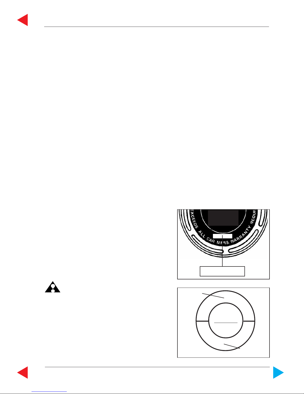
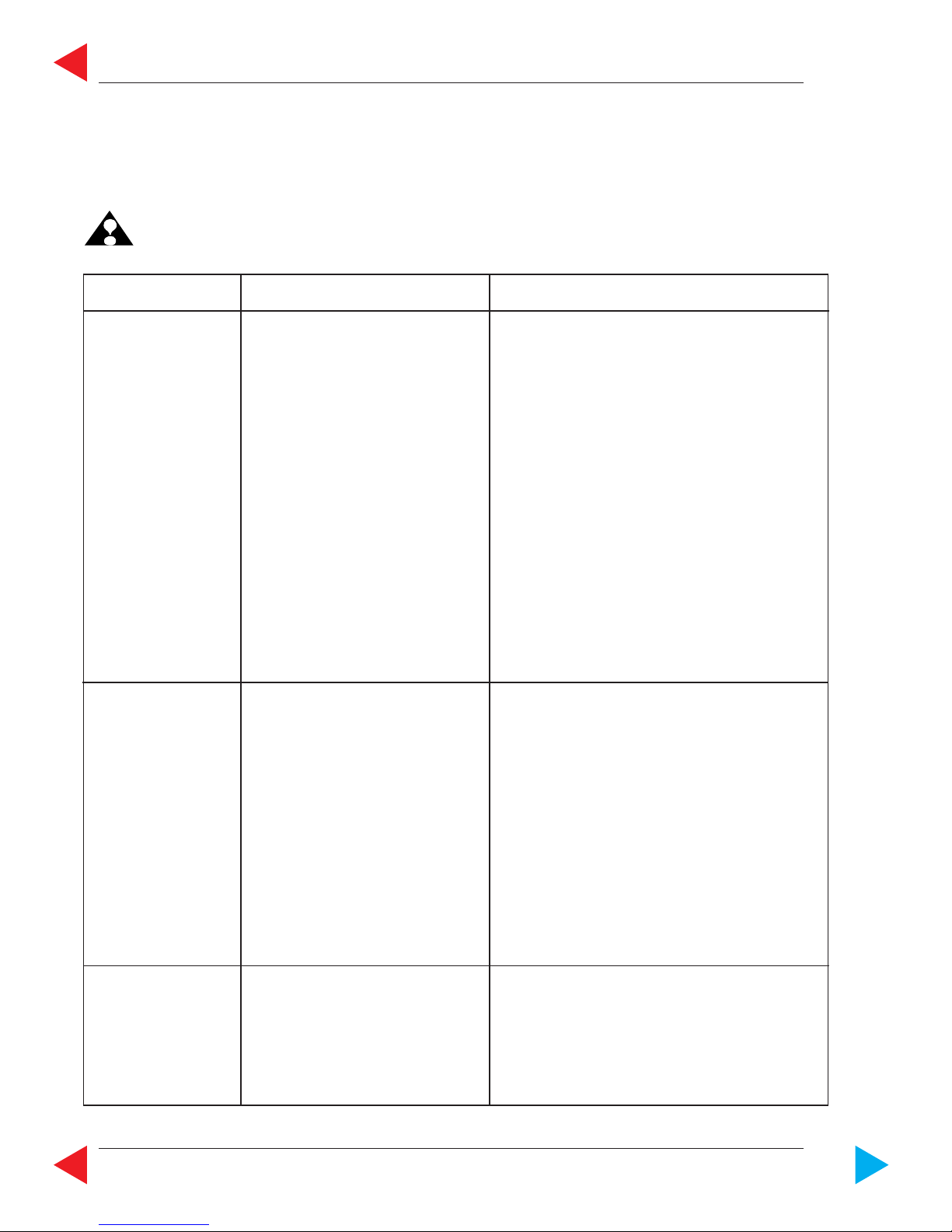
Oil Identification Symbol
Motor oils are specified by ACEA, API
service code and SAE viscosity numbers.
These may be found on the label, top of can, or oil
identification symbol.
NOTE: Some motor oils have several ACEA / API quality
ratings.
The recommended ACEA /API service letter code
must be among these quality ratings.
ill.1 Top of Can
ill.2 Oil Identification Symbol
SAE
5 W-50
10 W-40
API
SERVICE CODE
CF
ACEA E7 or B4 - 02
FOR HEAVY DUTY
DIESEL ENGINES
ACEA E7 or B4-02
API CF
GENERAL
Page GENERAL-22 Z001019/0_8_Octobre 2011
SERVICE MANUAL MARINE ENGINES
ToC
C Maintenance and Service
ATTENTION:
After following the “Action” described in chart, and before cranking the engine, make sure
there are no loose fuel connections. Make sure engine compartment is free of fuel vapours.
Failure to do so could result in fire.
SYMPTOM POSSIBLE CAUSE ACTION
Engine won’t start 1. No fuel in tank or shut-off valve Fill tank or open valve.
closed.
2. Air leak in suction lines. Bleed fuel system and check for leaks.
3. Fuel line plugged or pump Fuel pump may be defective.
defective.
4. Poor fuel quality. Replace fuel .
5. Water in fuel filter. Replace or drain water from fuel filter.
Check fuel supply for water contamination. If water
is present, drain fuel tank and flush with fresh fuel.
6. System error or failure. Check Engine Management System
display for service code.
7. Battery output insufficient Charge or replace battery.
Only for SOLAS ==> 8. Inversion switch actuated Cancelled by ignition "OFF - ON"
Starter won’t crank 1. Battery connections loose or Check for loose connections
engine corroded and corrosions. Clean connections and
thighten.
2. Battery is dead Check level of electrolyte and charge
battery.
3. Starter connections loose Check connections and tighten.
If solenoid clicks when attempting to
start engine, check starter.
4. Ignition switch If inoperative, replace.
6. Starter auxiliary relay Check terminal connection and function of relay.
Engine runs erratically 1. Water, air and/or dirt in fuel filter Replace filter. Inspect fuel supply line.
2. Anti-siphon valve stuck Clean and inspect or replace. (Tank)
3. Fuel pump Check operation of pump.
Replace fuel pump.
C 1 Trouble Check Chart
5. Fuse blown on panel
Check and replace if defect
 Loading...