

Page 1
TO THE INSTALLER: BE SURE TO LEAVE THIS MANUAL WITH THE OWNER.
ABT-EM-1005
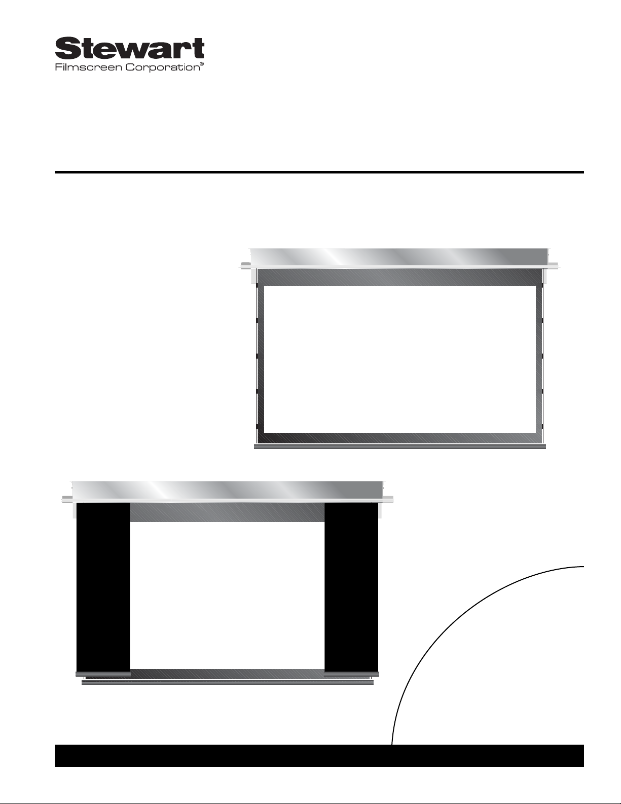
ABT-EM T rapdoor ElectriMask
Electriscreen
To the Owner
Installation Instructions
Operating the Screen
Maintenance
OWNER’S MANUAL
Page 2

Printed in U.S.A.
©2002 - 2005 Stewart Filmscreen Corporation
Stewart Filmscreen reserves the right to make changes to the product specified in this document.
From time to time, this document is updated. Current versions of documentation are posted on the Stewart Filmscreen website at
www.stewartfilm.com.
Page 3

Contents
To the Owner . . . . . . . . . . . . . . . . . . . . . . . . . . . . . . . . . . . . . .2
Preparing the Installation . . . . . . . . . . . . . . . . . . . . . . . . . . . . .3
Step 1. Hanging the Case . . . . . . . . . . . . . . . . . . . . . . . . . . . . .5
Step 2. Electrical Hook-up . . . . . . . . . . . . . . . . . . . . . . . . . . . .6
Operating the Screen . . . . . . . . . . . . . . . . . . . . . . . . . . . . . . .13
Adjusting the Screen Extension . . . . . . . . . . . . . . . . . . . . . . .14
Screen Care and Cleaning . . . . . . . . . . . . . . . . . . . . . . . . . . .16
Troubleshooting . . . . . . . . . . . . . . . . . . . . . . . . . . . . . . . . . . .18
ABT-EM Trapdoor ElectriMask Electriscreen: Owner’s Manual 1
ABT-EM T rapdoor
ElectriMask Electriscreen
OWNER’S MANUAL
Page 4
Congratulations on your purchase of the finest optical viewing screen
available anywhere in the world!
Please take a moment to review this manual, it will help ensure you many
years of trouble-free service from your new Stewart Filmscreen product.
About your ABT-EM Trapdoor ElectriMask Electriscreen
Your ABT-EM ElectriMask Electriscreen offers the most technologically
advanced trapdoor roller screen in the world. The hingeless door is
powered by its own motor. Sound dampers ensure quiet operation.
The ElectriMask system is designed to integrate with the latest multi-format
video projectors, which are capable of variable sizes and aspect ratios for
viewing standard broadcast television and the wide format seen in
commercial theaters (“letterbox”). The term aspect ratio refers to the format
(width to height) in which your home cinema sources are produced.
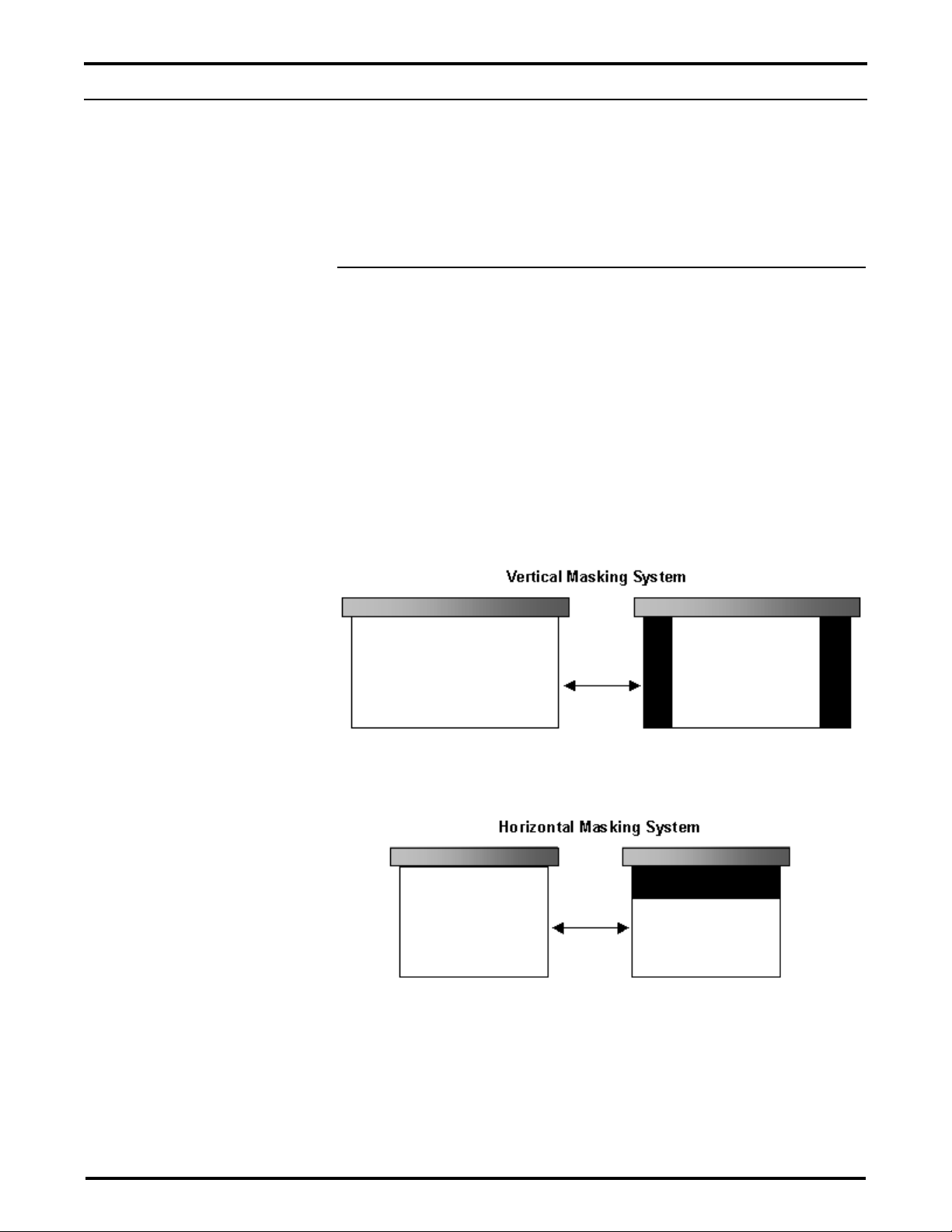
Your screen is equipped with either a vertical masking system to achieve a
1.33:1 aspect ratio (see Figure 1) or a horizontal masking system to achieve
a 1.85:1 aspect ratio (see Figure 2).
Figure 1: Vertical masking system
Figure 2: Horizontal masking system
2 Stewart Filmscreen Corporation
TO THE OWNER
1.85:1 Format Screen
Converts to
1.33:1
Standard
Video NTSC
Format
1.85:1 Format
“Letterbox”
1.33:1
Standard
Video NTSC
Format
Converts to
Page 5
Preparation
Specifications regarding the individual screen dimensions, weight, mounting
type, and controls are provided by the factory when the unit is ordered.
Before beginning the installation:
Check the specifications for the type of mounting and switch
control to be used.
Ensure that the mounting area and electrical connection are
prepared.
Check the size and weight of the screen to be installed so that
you can plan for the number of people required for the mounting
procedure. You need at least two people to mount the smaller
screens; more are needed for larger, heavier screens.
You will need:
Enough ladders for the personnel supporting the screen during
the mounting process
Alevel
Fasteners appropriate for the surface on which the screen is
being mounted (See instructions for the type of mount for
recommendations.)
A5/32” (.4 cm) hex head or Allen wrench
ABT-EM Trapdoor ElectriMask Electriscreen: Owner’s Manual 3
PREPARING THE INSTALLATION
Before proceeding with the installation of this screen,
take time to thoroughly read and understand these
installation and operation instructions.
All electrical wiring installations must conform to local
and national codes and should be performed by
qualified service personnel.
There are no user-serviceable parts contained within
the unit.
Caution
During installation, do not place the unit on an unstable
cart, stand, table, or ladder. The unit may fall, causing injury
to a child or adult and damage to the unit.
Page 6
Unpacking
1. DO NOT remove the paper hanging from the trapdoor at this
time. You should remove it only after the unit is hung, all electrical
connections have been made, and the screen is in operation.
2. When moving the unit, make sure not to torque or twist the case.
This can cause door alignment problems.
4 Stewart Filmscreen Corporation
Factory Advisory
The factory advises against installing a concealed or
recessed electrical projection screen permanently. You
must be able to access the external end plates should
future service to the internal roller tube/screen assembly
system be necessary.
Page 7
ABT-EM Trapdoor ElectriMask Electriscreen: Owner’s Manual 5
STEP 1. HANGING THE CASE
Professional mounting techniques should be used. Stewart Filmscreen
Corporation cannot be liable for substandard or faulty installations.
Make sure that you mount the screen so that the electrical box is on the left
side (audience left).
Installing the unit
The ABT-EM Electriscreen is ready to install into the ceiling or soffit. Afalse
ceiling is not intended to support the weight of an ABT-EM Electriscreen.
The screen can be bolted directly to the support structure or suspended. If
the unit is to be mounted to plaster, drywall, masonry, or other type of
surface, use an appropriate fastener.
1. Install the unit onto the support structure making sure that the
bottom of the case is flush with the finished ceiling.
2. Make sure the unit is level.
3. Make sure the case is not twisted or torqued lengthwise when
installed. (This can cause door alignment problems and
microswitch shutoff failure.)
4. Drywall or other ceiling material may be screwed directly to the
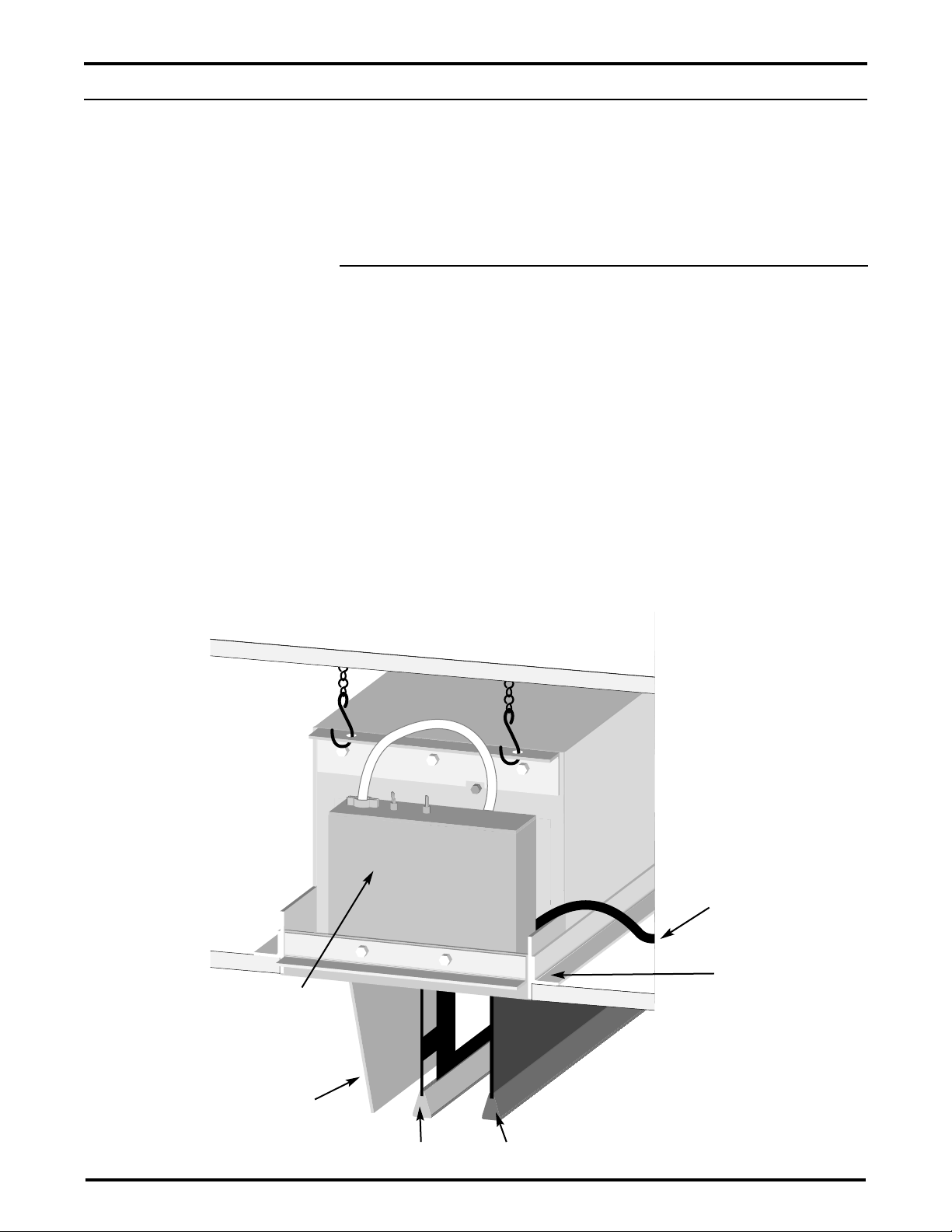
ceiling flanges on the case. Refer to Figure 3.
Support Structure
Electrical Connection
Housing
Note: Your housing may differ
based on the switches used.
Screen Mask
Flange
Main AC Wire
Trapdoor
Note: The two toggle
switches are used by the
factory only. Do not adjust.
(For proper positioning, the
left switch should be flipped
toward the unit, the right
switch should be straight up.)
Figure 3: ABT-EM Electriscreen-side view
Page 8
The ABT-EM Electriscreen has two roller tubes within the screen unit—one
for the main screen and one for the mask. Each roller has its own motor
and functions independently.
6 Stewart Filmscreen Corporation
The motor requires standard AC input (unless an alternate voltage has been
specified).
There are several kinds of switch controls available. Follow the installation
procedure for the type of switch control you will install.
General suggestions for wiring:
Soldering is recommended.
The use of wire nuts is acceptable.
On models not provided with armored whip, a romex connector
should be installed in the appropriate electrical KO (Knock Out).
Preparation—Removing access panel
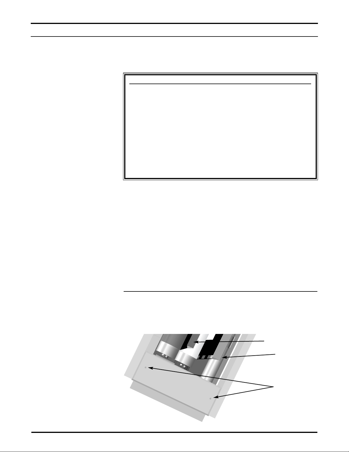
All connections are made to the electrical box on the side of the unit
(audience left). An access panel covers the electrical connections. To
remove the access panel on the underside of the unit, remove the two hex
screws. Refer to Figure 4. Replace the access panel after the electrical
connections have been made.
STEP 2. ELECTRICAL HOOK-UP
Caution
Professional techniques should be used when making any
electrical connection. A qualified electrician should perform
these procedures.
Be sure to follow all standard safety procedures for
installing electrical devices.
Do not disassemble or alter the configuration of the motor
or the unit's electrical connections. This may cause injury to
you or damage to the product.
The electrical connection should be made only to the type
of power source indicated on the marking label.
Figure 4: ABT-EM Electriscreen-underside view
Screen
Masking Panel
Hex Screws
Access Panel
Page 9
ABT-EM Trapdoor ElectriMask Electriscreen: Owner’s Manual 7
Installing the low-voltage 3-button switches (horizontal)
There are three low-voltage controls mounted on a board. Each low-voltage
control allows the use of low-voltage wire to connect to the supplied 3position 24V momentary wall switch. The top low-voltage box controls the
mask, the middle box controls the screen, and the bottom box, nearest the
J-boxes, controls the door. Refer to Figure 5.
Note: The board can be mounted near the screen, or by adding extra
cable, you can mount it farther away.
Preparing the connection
Before making the electrical connections, you need:
An available AC constant power source
A4-conductor switch hook-up cable (4-conductor bell wire or
category 5 cable is typically used for long runs)
Cat 5, multi-conductor unshielded, or similar type electronic cable
can be used to connect the 3-button switch to the LVC. The
recommended wire gauge is 20 to 24 AWG. Use plenum-rated
cable when required.
Making the connection
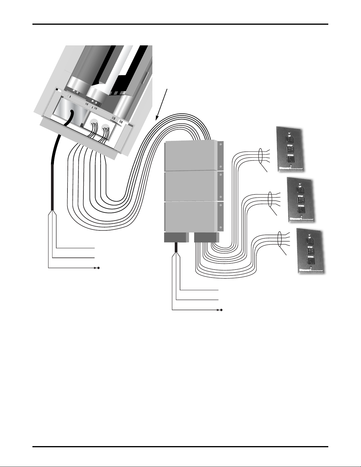
Figure 6, on the following page, illustrates the connections.
Note: The electrical housing has a 2-gang J-box. For a top view, refer to
Figure 4.
1. Connect the 8-conductor cable to the connection harness coming
from the J-box labeled “switch input” on the screen unit.
Note: Use a longer cable to mount the low-voltage control board
further from the screen unit.
2. Connect the 4-conductor cable to the connection harness coming
from the low-voltage control board.
3. Connect the hookup cable to the 3-button switch.
4. Connect the main AC power source to the the low-voltage board.
5. Connect the main AC power source to the the J-box labeled
“main AC power connection” on the screen unit.
6. A parallel connection to an outboard audio-visual switching
network can be made at this time. (optional)
Caution
Refer to the First Time
Activation note in the
section “Operating the
Screen.”
Page 10
8 Stewart Filmscreen Corporation
Figure 5: Low voltage 3-button switch wiring
3-button Momentary
Switches
Screen
Door
8 Conductor Hook-up Cable - 18ga Minimum Category 5
recommended (NOT Supplied)
STOP-Yellow
COMMON-White
DOWN-Black
4 Conductor Hook-up Cable—20-24ga Recommended
Category 5 Typically Used (NOT Supplied)
STOP-Yellow
COMMON-White
UP-Red
DOWN-Black
UP-Red
NEUTRAL-White
GREEN-Ground
HOT-Black
NEUTRAL-White
GREEN-Ground
HOT-Black
Mask
Note: The cable wires can be split with extra length
added so that you can move the control units to a
location at a distance from the screen case.
Page 11
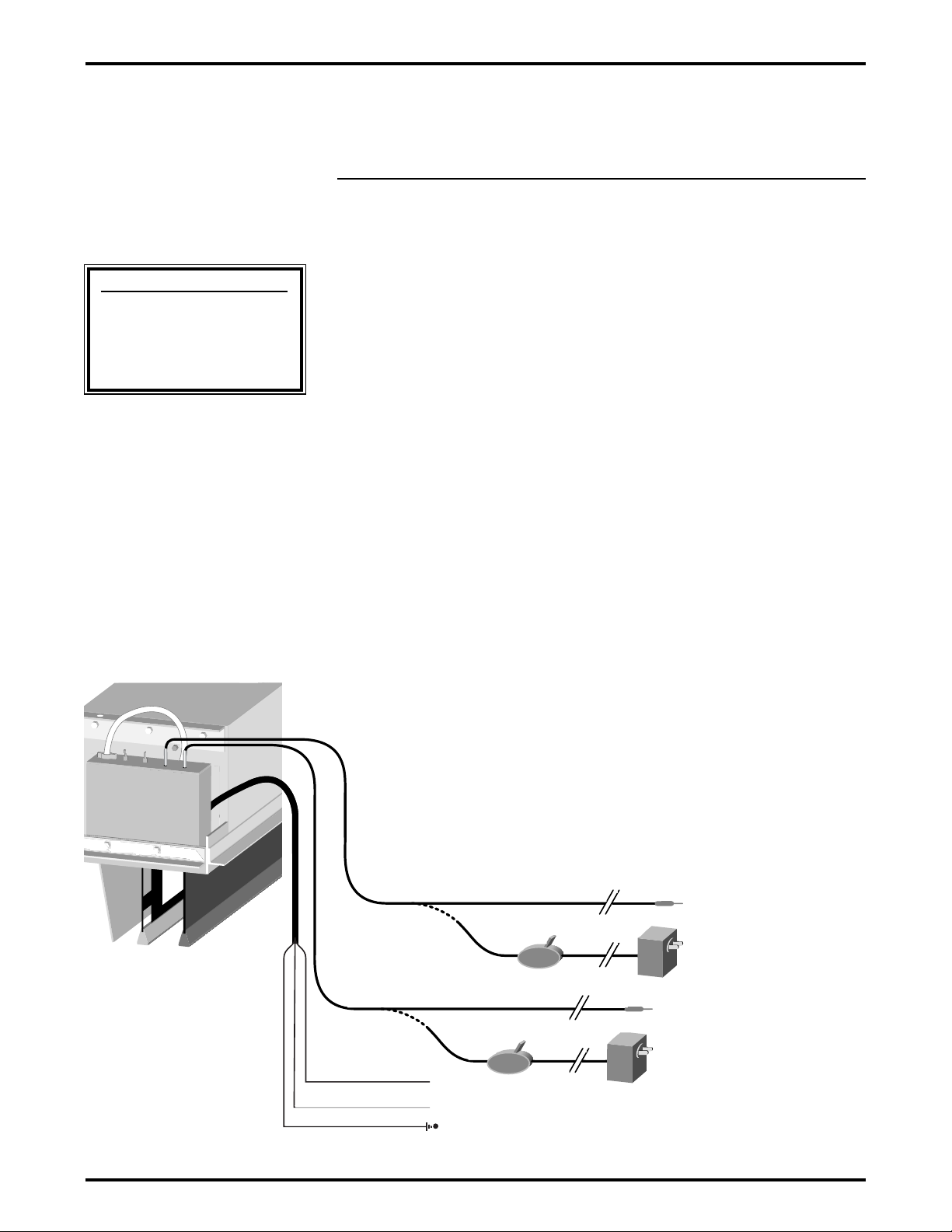
Connecting the dual screen trigger interface option
(vertical masking)
Note: The dual screen trigger interface option is not available for the
horizontal masking system.
The optional 12V screen trigger interface enables up and down operation of
the screen and mask in conjunction with a projector, tuner, VCR, cable box,
or switched AC outlet.
Once the AC power outlet is installed near the screen, an electrician is not
needed to connect the screen trigger interface to the power source.
Note: An optional 12V DC transformer is used if there is no 12V power
source from the projector or AV control center.
Preparing the connection
Before making the electrical connections, you need:
An available AC constant power source installed near the screen
Making the connection
Figure 6 illustrates the connections.
1. Attach each 12V trigger wire to the jack on the box.
2. Connect the main AC power source to the the J-box labeled
“main AC power connection.”
Note: The two toggle switches on the electrical connection housing are
used by the factory only. Do not adjust.
ABT-EM Trapdoor ElectriMask Electriscreen: Owner’s Manual 9
Figure 6: Dual screen trigger interface connection
Optional 12V DC
Transformer with Switch
Screen
Mask
Optional 12V DC
Transformer with Switch
To Projector
or
AC Power Supply
To Projector
or
AC Power Supply
NEUTRAL-White
GREEN-Ground
HOT-Black
Caution
Refer to the First Time
Activation note in the
section “Operating the
Screen.”
Page 12
10 Stewart Filmscreen Corporation
Connecting the screen trigger interface and low-voltage
option (vertical masking)
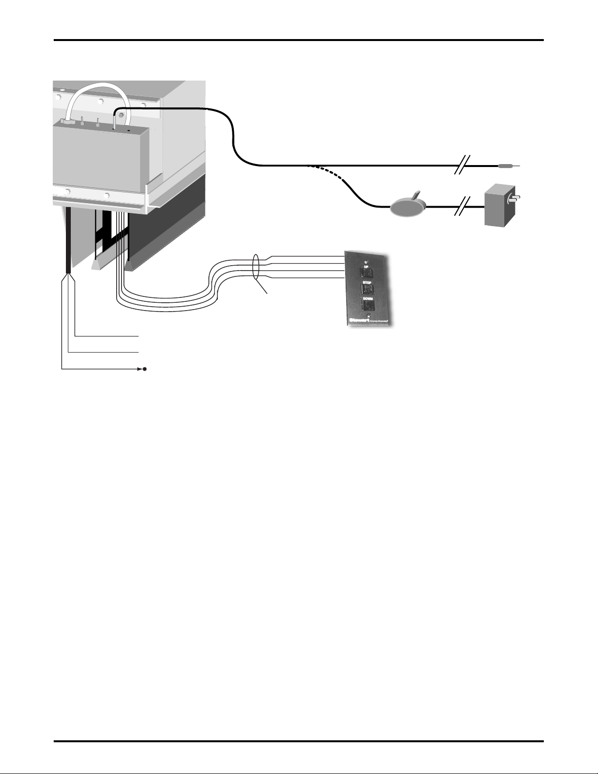
The optional 12V screen trigger interface enables up and down operation of
the door and screen in conjunction with a projector, tuner, VCR, cable box,
or switched AC outlet. The low-voltage control switch controls the vertical
masking panels.
An optional infrared sensor can be installed with the low-voltage control box.
This allows an infrared remote control to adjust the vertical masking panels.
Note: An optional 12V DC transformer is used if there is no 12V power
source from the projector or AV control center.
Preparing the connection
Before making the electrical connections, you need:
An available AC constant power source installed near the screen
A4-conductor switch hook-up cable (4-conductor bell wire or
category 5 cable is typically used for long runs)
Cat 5, multi-conductor unshielded, or similar type electronic cable
can be used to connect the 3-button switch to the LVC. The
recommended wire gauge is 20 to 24 AWG. Use plenum-rated
cable when required.
Making the connection
Figure 7 illustrates the connections.
1. Attach the 12V trigger wire to the jack on the box.
2. Connect the main AC power source to the the J-box labeled
“main AC power connection.”
3. Connect the 4-conductor cable to the connection harness coming
from the J-box labeled “switch input.”
4. Connect the hookup cable to the 3-button switch.
Note: The two toggle switches on the electrical connection housing are
used by the factory only. Do not adjust.
Caution
Refer to the First Time Activation note in the section
“Operating the Screen.”
Page 13
ABT-EM Trapdoor ElectriMask Electriscreen: Owner’s Manual 11
Figure 7: Screen trigger interface and low-voltage connections
for vertical masking unit
NEUTRAL-White
GREEN-Ground
HOT-Black
Optional 12V DC
Transformer with Switch
Door and Main Screen Operation
To Projector or AC Power Supply
4 Conductor Hook-up Cable—
20-24ga Recommended
Category 5 Typically Used (NOT
Supplied)
STOP-Yellow
COMMON-White
DOWN-Black
UP-Red
3-button
Momentary Switch
Masking control
Page 14
12 Stewart Filmscreen Corporation
Connecting the high-voltage switch control (vertical
masking)
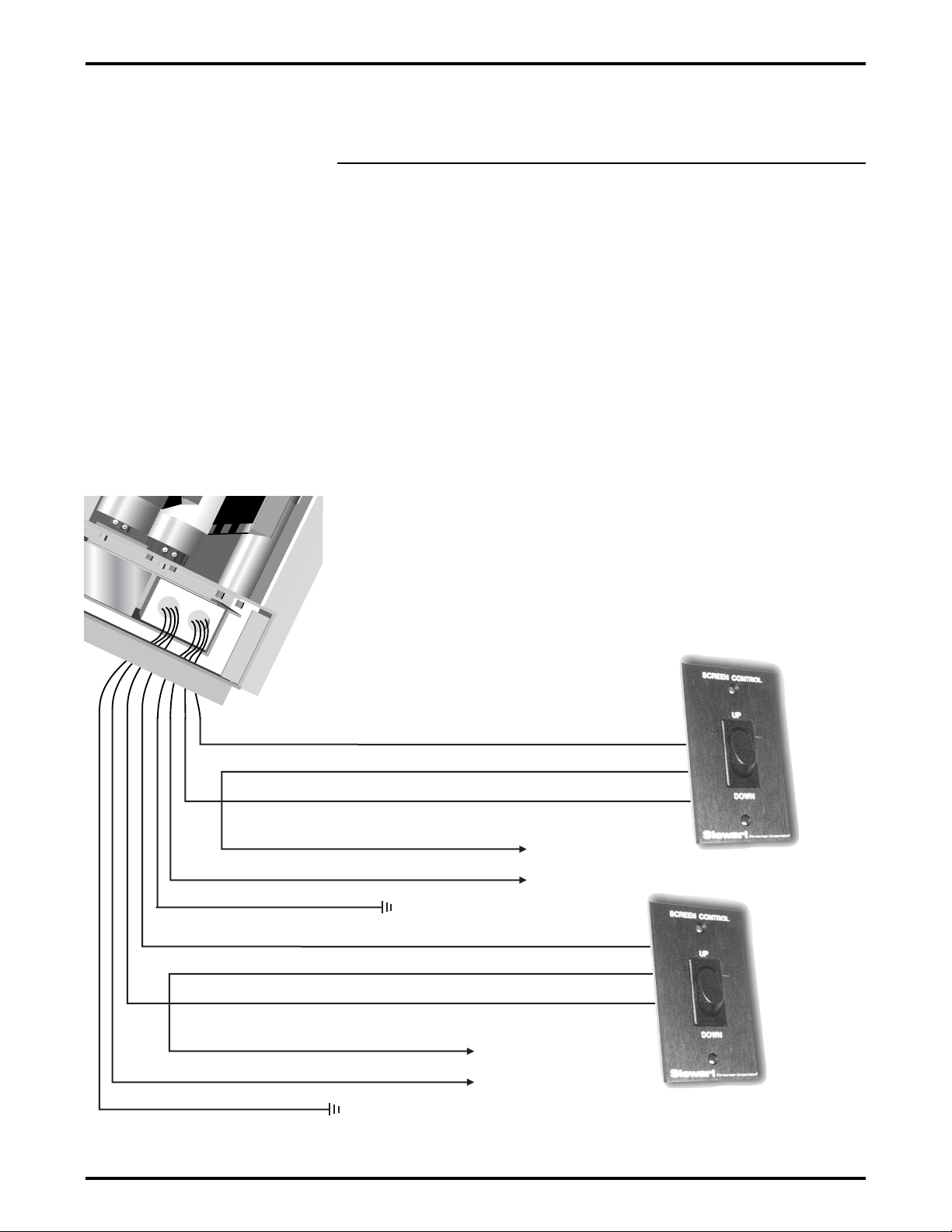
A standard 3-position AC wall switch is supplied. The high-voltage control is
connected to the electrical source. It alternates directions of mask motion by
means of the hot lead, using the 3-position switch.
Preparing the connection
Before making the electrical connections, you need:
An available AC constant power source
A 4-conductor romex or motor connector cable
Making the connections
Figure 8 illustrates the connections.
1. Connect the wall switches to the AC constant power source.
2. Connect the wall switches to the unit’s electrical box.
Figure 8: High voltage control wiring diagram
Door & Screen Switch
AC Power
Source
DOWN-Black
UP-Red
Line (Hot)
COMMON-White Neutral
Mask Switch
AC Power
Source
DOWN-Black
UP-Red
Line (Hot)
COMMON-White Neutral
GROUND-Green
GROUND-Green
Page 15
ABT-EM Trapdoor ElectriMask Electriscreen: Owner’s Manual 13
OPERATING THE SCREEN
Caution
Do not operate the
motors when any of the
following occurs:
The unit emits any
smoke, heat,
abnormal noise or
unusual odor.
The unit is
damaged in some
way, such as
damage from a
water leak.
If any of these
situations occur, call a
qualified service
person.
First time operation
The first time you operate the screen, the protective paper
will fall out as the screen unrolls. Once the screen is fully
displayed, make sure that no packing paper remains on the
screen roll. The screen can be damaged if loose paper
remains.
First time activation for screen trigger interface
The STI input must be supplied with 12V DC power before
the main AC power is activated. Due to factory screen
packing procedures, the main screen roller may not be in
the fully up (motor off) position.
First time activation for horizontal screen
You must remove the shipping lockdown brackets. To do
this, operate the screen so that the door opens, then stop
the operation. Unscrew and remove the shipping lockdown
brackets.
The method you use to raise and lower the screen and mask depends on
the type of switch control device you have selected.
Use the masking screen as needed to establish the appropriate viewing
format.
When you lower or retract the screen or mask, they will stop at their preset
limits. If an obstacle (such as a person or furniture) gets in the path of the
screen as it is lowered, you should use the switch control to stop the
screen's motion; it will not automatically stop if it hits an obstacle.
The motor is designed to be used for short operations such as lowering the
screen (or mask) in preparation for viewing. The motor is not designed for
continuous duty. If the motor operates continually for more than a few
minutes, it may automatically shut off to prevent damage from overheating.
If the motor occasionally needs to be run more than normal, for example
during initial setup and positioning, allow time for the motor to cool down.
In general, when the screen is not in use, you should store it in the fully
retracted position.
Page 16
14 Stewart Filmscreen Corporation
Each roller tube has a set of limit switches. The extension and retraction
limit switches have been preset at the factory. In general, we advise you to
avoid readjusting these switches.
In some cases, to enable proper alignment of the displayed image on the
screen, you may need to adjust the extension of the screen or the mask. If
adjustment to the extension is necessary, carefully follow these instructions.
Caution
Improper adjustment of the limit switches can cause
irreparable damage to the screen itself, resulting in voiding
the factory warranty.
Warning!
The screen and mask are fully retracted when the battens
are flush with the bottom of the case. Do not attempt
adjustments with the yellow retraction (UP) limit switch that
will further retract the screen. Incorrect adjustment of the
switch will cause severe screen damage. Please consult the
factory if you have any questions.
A
DJUSTING THE SCREEN
EXTENSION
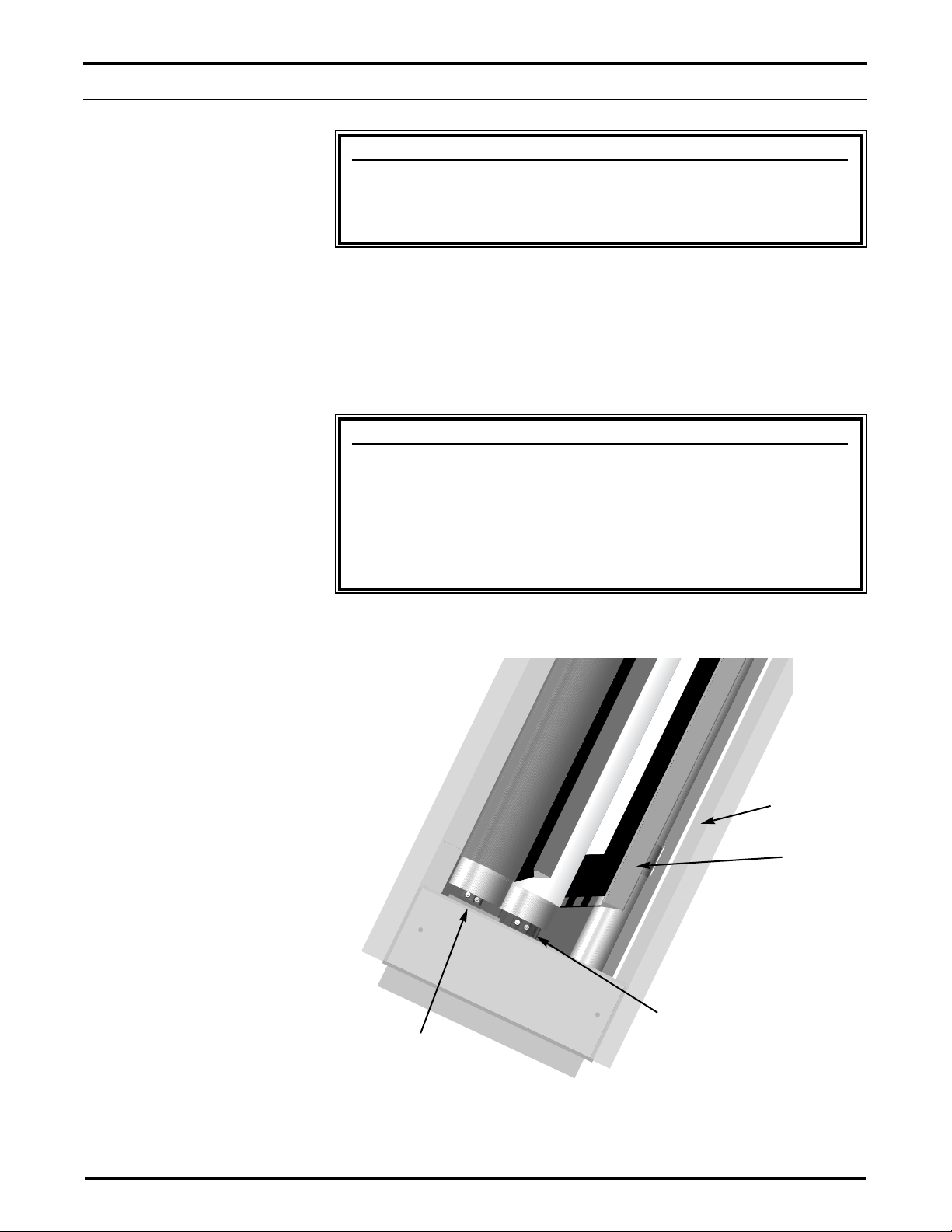
Figure 9: Underside view
Screen Limit
Switches
Mask Limit
Switches
Trap Door
Screen
Page 17

ABT-EM Trapdoor ElectriMask Electriscreen: Owner’s Manual 15
Modifying the extension of the screen and the mask
You can increase the extension of the screen and mask up to 3" / 7.6 cm
past the factory preset stop, or you can decrease the extension by
approximately
4-6" (10 - 15 cm) from the factory preset stop. Do not attempt to modify the
screen extension beyond these recommended amounts.
The limit switches are located on the left side of the screen roller tube inside
the case, as shown in Figure 9.
To increase the screen's fully extended (screen down) stop position:
1. Lower the screen or mask to its current stop position.
2. Locate the white extension (down) limit switch located on the left
side of the screen tube. Use a screwdriver to turn the switch in a
counterclockwise direction. If the power is on, the screen will
drop incrementally as the switch is turned.
Note: One complete turn of the switch will make approximately a
3/4" (2 cm) change in the screen or mask’s stop position.
To decrease the screen extension:
1. Lower the screen or mask until it is extended about halfway
down.
2. Locate the white extension (down) limit switch located on the left
side of the screen tube. Use a screwdriver to turn the switch in a
clockwise direction.
Note: One complete turn of the switch will make approximately a
3/4" (2 cm) change in the screen or mask's stop position.
3. Activate the screen in the down direction until it reaches the
newly reduced stop position. Repeat this procedure until the
desired stop position is reached.
Once you have made the adjustment, whenever you lower the screen or
mask, it will automatically stop at the new position.
Note: It is recommended that you make a note of any changes made to the
factory preset.
Page 18

This warranty covers defects in materials and workmanship for a period of
one (1) year from the date of installation, not to exceed fifteen (15) months
from the date of shipment, provided this product is installed in a normal
environment and maintained according to written instructions in the product
Owner’s Manual. Stewart Filmscreen warrants against loss of usefulness,
discoloration or deterioration of optical quality within the warranty period as
a result of manufacturing or material defects.
A factory authorized returned screen arriving prepaid to our facility for
inspection and proved defective due to an inherent manufacturing fault will
be repaired or replaced by Stewart Filmscreen Corp. This warranty
expressly does not cover any costs of removal, installation, framing, or other
incidental costs to replacing the screen or returning it to the manufacturer.
Should you encounter a perceived product fault or problem, contact your
dealer regarding application of this warranty.
16 Stewart Filmscreen Corporation
With reasonable care, you may expect many years of trouble-free use of
your Stewart projection screen.
We encourage you to keep your screen clean. To protect your screen when
it is not in use, store it in the fully retracted position.
Avoid getting any foreign material on the screen, as cleaning may prove
very difficult. It may not be possible to remove scratches, paint, ink, etc.
General maintenance
The screen surface on your screen is delicate. Special attention to these
instructions should be followed when cleaning.
Adraftsman-style brush may be used to lightly whisk away any
loose dirt or dust particles. (This type of brush is usually available
at office supply stores.) Stewart Filmscreen has an optional
screen cleaning kit that contains the proper type of brush.
Contact your dealer if you would like to obtain this cleaning kit.
Particles left on the screen when it is retracted into the case may
form an impression on the screen surface. Periodically wipe the
back of the screen with a clean damp cloth.
For tougher spots, use a solution of mild detergent and water.
Rub lightly using a sponge. Blot with a damp sponge to absorb
excess water. Residual water marks will evaporate within a few
minutes. Let the screen air dry completely before retracting.
Do not use any other cleaning materials on the screen. Contact the factory
if you have questions about removing difficult spots.
Replacement parts and service
No user-serviceable parts are contained within the unit. Contact your dealer
or the factory if you require part replacement or service.
SCREEN CARE AND CLEANING
PR ODUCT WARRANTY
Page 19
Refer to the following guidelines if you encounter a difficulty in the operation
of your Stewart Filmscreen. Problems related to electrical or motor function
may require a qualified service person or electrician.
Should you have a problem that is not addressed here, call the Stewart
Filmscreen Corporation.
ABT-EM Trapdoor ElectriMask Electriscreen: Owner’s Manual 17
TR OUBLESHOOTING
Problem description
Probable cause
Action to take
Door won't open.
Screen won't operate.
No AC power available.
Outboard switching problem.
Check to see if the circuit breaker has switched off.
Reset if needed.
Check outboard switching apparatus.
Check voltage availability. Contact an electrician.
Check that the toggle switches are in the correct
position. See Figure 3, p. 5.
Screen or mask won't roll up
or down (even though power
is available).
Bad connection at switch.
Polarity of STI line may be bad.
Have an electrician or qualified service person check
the connection as follows:
· If you have a low voltage control unit, check switch-
line connections.
· If you have a high voltage control switch, check
switch-line connections.
· If you have a screen trigger interface, check line
connections, or the mini-plugs at the screen input or
projector output. Check 12V DC line for correct
polarity. Contacts may be sticking—tap relay to free
contacts.
Roller tube motors chatter
when power is activated.
Can be caused by voltage drop,
bad connections, or a defective
switch.
Have an electrician or qualified service person check
all hook-ups including all outboard wiring.
Unit hums in up mode.
(Screen or mask has already
retracted.)
The screen batten is retracting too
far into the case. Failure to
correct can damage motor and
screen. Do not use the unit until
this problem is resolved.
Have a qualified service person adjust the yellow UP
limit switch. Turn the adjusting screw clockwise.
Screen or mask drops when
up direction is activated
(grinding noise occurs).
Drop in voltage.
Motors require full voltage. Have an electrician or
qualified service person check available voltage.
Screen or mask continues
past bottom stop position.
White limit switch is out of
adjustment.
Readjust the white DOWN limit switch. See pp. 14-15
of this manual.
Battens retract too far into
case.
Yellow limit switch out of
adjustment. Failure to correct
can damage motor and screen.
Do not use the unit until this
problem is resolved.
Have a qualified service person readjust the yellow
UP limit switch. See pp. 14-15 of this manual.
Motor shuts off. Motor has
been in use for more than
2 minutes.
Motor is designed for short
operations (lowering and
retracting), not continuous duty.
Longer operation, such as during
setup and positioning, causes the
motor to overheat and shut off.
Allow the motor to cool down. Complete cooling can
take an hour or more. Heat gain is cumulative and
takes time to dissipate. If motor use is initiated before
it has cooled completely, the motor will shut down
again when it reaches maximum temperature.
Any controller (e.g., STI,
LVC, etc.) fails to operate
motor.
Dirt, finger prints, marks, etc.
on screen surface.
Improper handling of screen.
Brush off or use a mild detergent solution with clean
rag or cotton swab.
Indentations appear on
screen surface.
Debris or particles adhering to
screen due to static cling.
Check back of screen; gently brush debris away by
hand.
Page 20

www.stewartfilm.com
1-800-762-4999 Fax (310) 326-6870
 Loading...