

Page 1
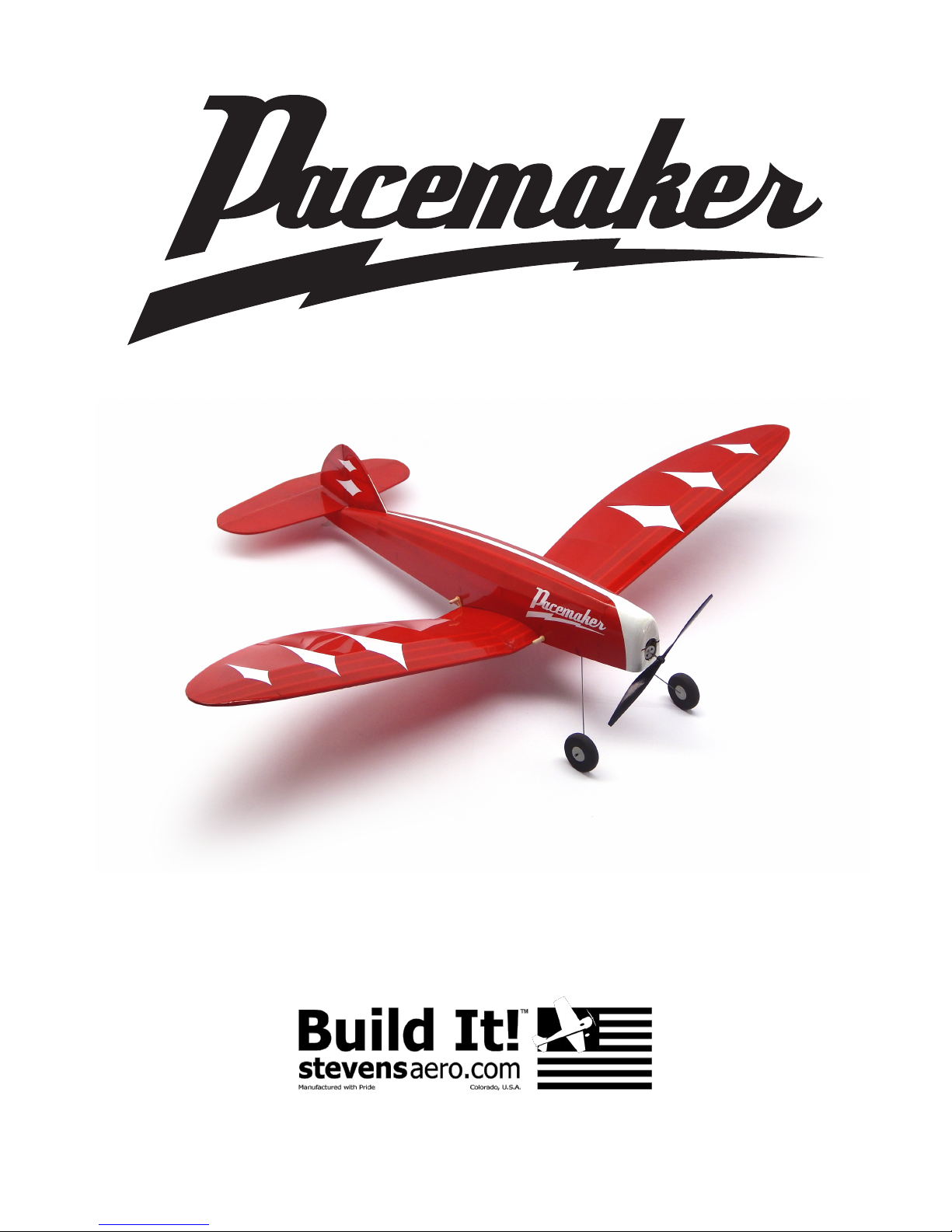
Wing Span: 27.25 inches | Wing Area: 100 square inches | Average Flying Weight: 2.25 ounces
Build Instructions - Version 1.18 (revised 11.05.2016)
Page 2
WARRANTY
Stevens AeroModel guarantees this kit to be free from defects in both material and workmanship at the
date of purchase. This warranty does not cover any component parts damaged by use or modification.
In no case shall Stevens AeroModel’s liability exceed the original cost of the purchased kit. Further,
Stevens AeroModel reserves the right to change or modify this warranty without notice.
LIABILITY RELEASE
In that Stevens AeroModel has no control over the final assembly or material used for final assembly,
no liability shall be assumed nor accepted for any damage resulting from use by the user. By the act of
using the user-assembled product, the user accepts all resulting liability.
If the buyer is not prepared to accept the liability associated with the use of this product, the buyer is
advised to return this kit immediately in new and unused condition to the place of purchase.
THIS PRODUCT IS NOT INTENDED FOR CHILDREN 12 YEARS OF AGE OR YOUNGER.
WARNING: This product may contain chemicals known to the state of California to cause cancer
and/or birth defects or other reproductive harm.
PRODUCT SUPPORT
This product has been engineered to function properly and perform as advertised, with the suggested
power system and supporting electronics as outlined within this product manual. Product support
cannot be provided, nor can Stevens AeroModel assist in determining the suitability or use of
electronics, hardware, or power systems not explicitly recommended by Stevens AeroModel.
For product assembly support, replacement parts, hardware, and electronics to complete this model,
please contact Stevens AeroModel at www.stevensaero.com.
Stevens AeroModel
26405 Judge Orr Rd., Colorado Springs, CO 80808 USA
719-387-4187 www.stevensaero.com
Build Instructions
Pacemaker 100 - Build Instructions © 2016 Stevens AeroModel, all rights reserved.! Page 2
Page 3

Build Instructions
Pacemaker 100 - Kit Inventory
☐
Laser-cut wood, 10 sheets (See Sheet Wood Inventory, page 5)
☐
Illustrated Build Instructions
☐
Plan Set, 2 sheets, 12 in. x 18 in.
Taped to back of wood brick:
☐
1 Landing gear, wire, .032 in. x 12 in.
☐
2 Push rods, wire, .015 in. x 18 in.
Hardware Bag:
☐
1 Delrin receiver clip (5013)
☐
1 Heat shrink tube, 1 1/2 in. x 1/16 in. (5012)
☐
1 Pair, plastic wheels, 1 1/8 in. diameter (5015)
☐
2 Hardwood dowel, 1/8 in. x 2 in. (1017)
☐
8 Rubber band, Size #16
Pacemaker - Background
This Laser Engineeredtm design from Stevens AeroModel was directly inspired by the classic JL Sadler
Pacemaker – A lovely “old timer” with a beautiful profile and elegant wing shape. The original Pacemaker
was designed in 1940 and is indeed a unique design for a “old timer” – it features a low wing, and while
not unheard of in the golden age of aeromodelling, it is a rare trait.
Our version of this classic bit of aviation history, the Pacemaker 100, captures the essence of this iconic
model. The Pacemaker 100, while reminiscent of those bygone years, offers a refreshingly modern
design that builds trouble-free and quickly, thanks to laser-cutting processes pioneered by Stevens
AeroModel.
Pacemaker 100 - Build Instructions © 2016 Stevens AeroModel, all rights reserved.! Page 3
Page 4

Build Instructions
Suggested Items to Complete this Model
Many of the suggested items listed below are available at your local hobby shop. For your convenience,
Stevens AeroModel stocks all the power system components and most of the building supplies required
to complete this kit. If you have difficulties sourcing any of these items locally, please visit our website,
stevensaero.com to purchase the items necessary to complete your model.
Required Electronics
RC transmitter with at least 3 channels
☐
Receiver/ESC/Servo brick (PKZ3352 or PKZUA1151)*
☐
Motor/Gearbox (PKZ3624)
☐
Propeller, 130mm x 70mm (EFL9051)
☐
LiPo battery, 120 - 160 mAh 3.7V
☐
*SPMAR6400 or SPMAR6410 may be used with computer radio.
Required Building Supplies and Tools
CA glue, medium, 1/4 oz (PAAPT04)
☐
CA glue, thin, 1/4 oz (PAAPT10)
☐
CA glue applicator tips (PAAPT21)
☐
CA glue accelerator (PAAPT15)
☐
Hobby knife with supply of #11 blades
☐
Sanding block with 400 and 600 grit paper
☐
Optional Building Supplies and Tools
Balsa filler
☐
Modeling clay (ballast)
☐
CA glue de-bonder (PAAPT16)
☐
Building Supplies and Tools
Covering iron and heat gun
☐
Needle nose pliers, small
☐
Clear tape, 1/2 in. (DUB916)
☐
Velcro for mounting battery (PKZ1039)
☐
Masking tape (low-tack blue painters’ tape)
☐
AeroLITE
☐
Required Building Supplies
☐
☐
Clear lacquer-based sealant (DEFT)
☐
Lacquer-based spray paint (Design
☐
TM
covering film
Master®)
Covering Film Requirements
While any high-quality covering film may be used to finish this model, superior results will be achieved by
using genuine AeroLITE brand covering film, available exclusively from Stevens AeroModel. The lower
working temperature and light weight of AeroLITE are especially desirable for this type of model.
AeroLITE is one-third the weight of typical model covering films, and will present a significant weight
savings when applied to this model.
3 - PatchPakTM AeroLITE
☐
Sealing Bare Wood
While not required, it is suggested that a high-quality clear lacquer be used to protect and seal any
unfinished wood. One single light coat of clear lacquer should be sufficient to protect the model from
moisture, without adding significantly to the model’s final flying weight.
Many parts of this model may be colored using a lacquer-based spray paint. Listed below are some of
the products we have used on our models. Please feel free to use whatever products you prefer.
DEFT clear lacquer-based sealant (available at most hardware stores)
☐
Design Master Color Tool, lacquer-based spray paint (available at most arts and crafts stores)
☐
Pacemaker 100 - Build Instructions © 2016 Stevens AeroModel, all rights reserved.! Page 4
Page 5
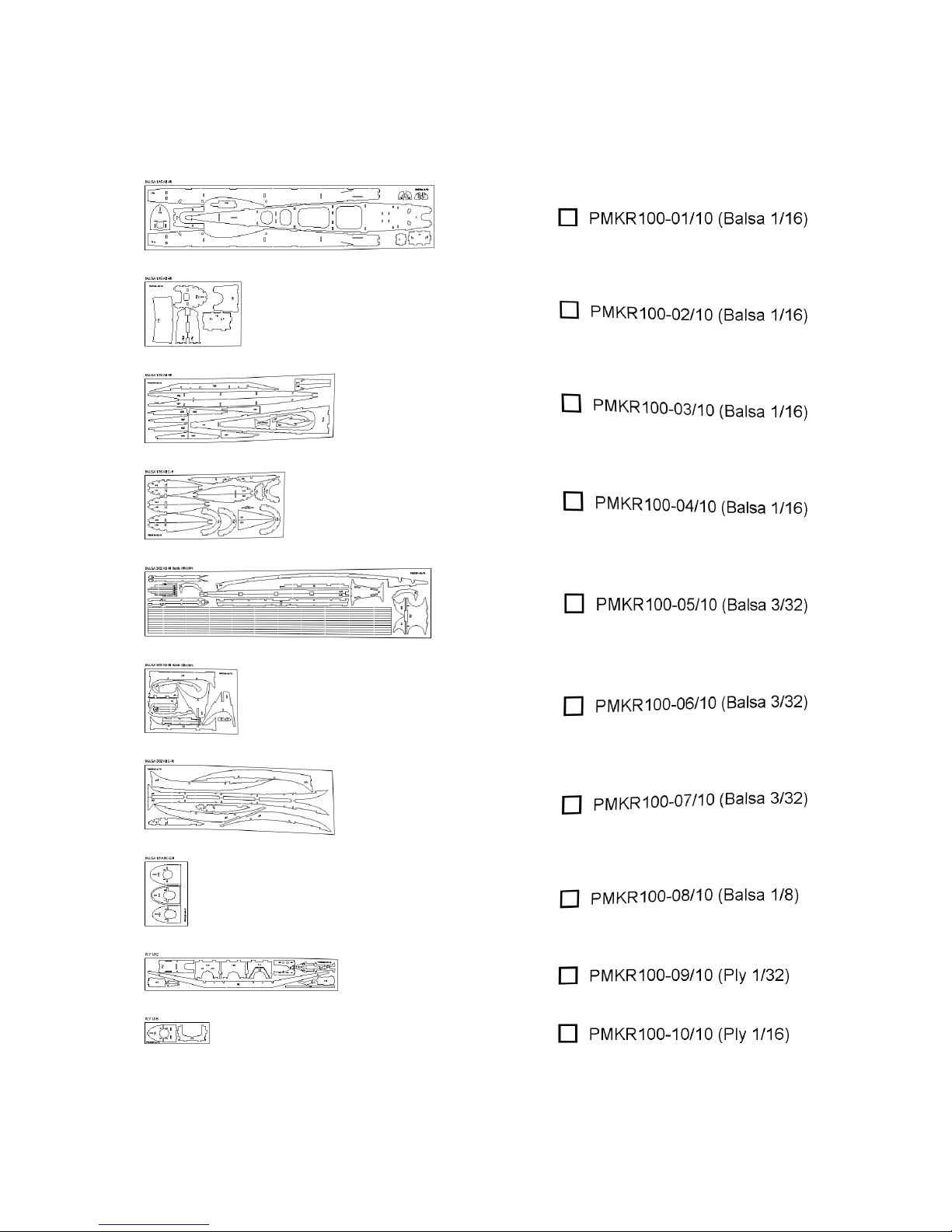
Sheet Wood Inventory (1 of 1)
Build Instructions
Pacemaker 100 - Build Instructions © 2016 Stevens AeroModel, all rights reserved.! Page 5
Page 6

Builder’s Notes
Build Instructions
Pacemaker 100 - Build Instructions © 2016 Stevens AeroModel, all rights reserved.! Page 6
Page 7

Build Instructions
General Assembly Instructions
Thank you for purchasing the Pacemaker 100 from Stevens AeroModel.
This model has been developed and manufactured using state-of-the-art CAD/CAM systems. Our kits
feature a unique interlocking construction process, that when compared to traditional building methods,
saves countless hours of measuring, cutting, sanding, and fitting. We are certain that you’ll find our kit to
offer a truly exceptional build experience.
As this kit is recommended for the novice model builder and pilot, we invite beginners who have
purchased this kit to seek the help of an experienced builder and pilot. If at any time during the assembly
of this kit, should you run across a term or technique that is foreign to you, please contact our staff with
your questions.
IMPORTANT!
Please READ and RE-READ these build instructions along with any other included documentation before
starting your build and/or contacting our staff for builder support.
Pre-Sanding
DO NOT SKIP THIS STEP. Before removing any parts from the laser-cut sheet wood, use a sanding
block loaded with 250 - 400 grit sandpaper and lightly sand the back side of each wood sheet. This step
removes any residue produced as a result of the laser cutting process. We have found that most stock
wood sizes run several thousandths of an inch oversized. This step also slightly reduces the thickness of
each sheet of wood. Leave all parts in the sheet wood until required for assembly.
Protecting Your Work Surface
Use the poly tube that this kit was shipped in as a nonstick barrier between your work surface and the
product assembly.
Bonding the Assembly
This product’s tabs and notches interlock like a 3D puzzle. We strongly suggest that when fitting parts,
you dry fit (use no glue) the parts together first. It is advised to work 1 - 2 steps ahead in the instructions,
using this dry-fit technique. This allows the opportunity to inspect the fit and location of assembled
components, and shows the benefits of our construction technique. As each successive part is added, it
contributes to pulling the entire assembly square. Once you arrive at the end of a major assembly
sequence, square your work on a flat work surface and bond the dry fit joints with glue. Using the dry-fit
process, you’ll be able to recover from a minor build mistake and will ultimately end up with a square and
true assembly.
Unless otherwise noted in the instructions, we find it easier to “tack glue” parts (temporarily bonding parts
in assemblies, using a small dot of glue). When using medium CA glue, apply with a fine-tip CA glue
applicator. Never bond painted or covered assemblies with thin CA, as it can destroy the finish of a
beautifully prepared model.
Never Force the Fit!
This is a precision laser-cut kit. Our lasers cut to within 5 thousandths of an inch in accuracy. Yet the
wood stock supplied to us by the mill may vary in thickness by up to 20 thousandths. This variance in the
wood stock can cause some tabs and notches to fit very tightly. With this in mind, consider lightly sanding
or lightly pinching a tight-fitting tab, rather than forcing the parts together. You will break fewer parts in
assembly, and end up with a square and true airframe.
Manual Updates
Please check our website for updates to these instructions before starting the build. To obtain downloads
and updates to this model aircraft kit, please visit the product page at stevensaero.com
Pacemaker 100 - Build Instructions © 2016 Stevens AeroModel, all rights reserved.! Page 7
Page 8

Build Instructions
Fuselage
Fuselage parts are designated with the letter “F” followed by a number. Parts have been numbered so
that the fuselage assembly follows a sequential order: F1 to F37.
Note: When initially bonding parts, use a single, small drop of medium CA glue, applied sparingly with a
CA glue applicator tip to “tack glue” the part in place. Should you commit an error in assembly, it will be
easier to recover from the mistake and remove or correct the part in error, if you do not soak the assembly
with glue after each step! This method of assembly will allow our interlocking design to do its job.
As each successive part is installed within the fuselage, it will help pull the entire structure square and
true. When a major assembly is completed, revisit all joints and bond completely. Do not use excessive
amounts of glue, as this only adds weight to the model.
□
□
□
□
□
□
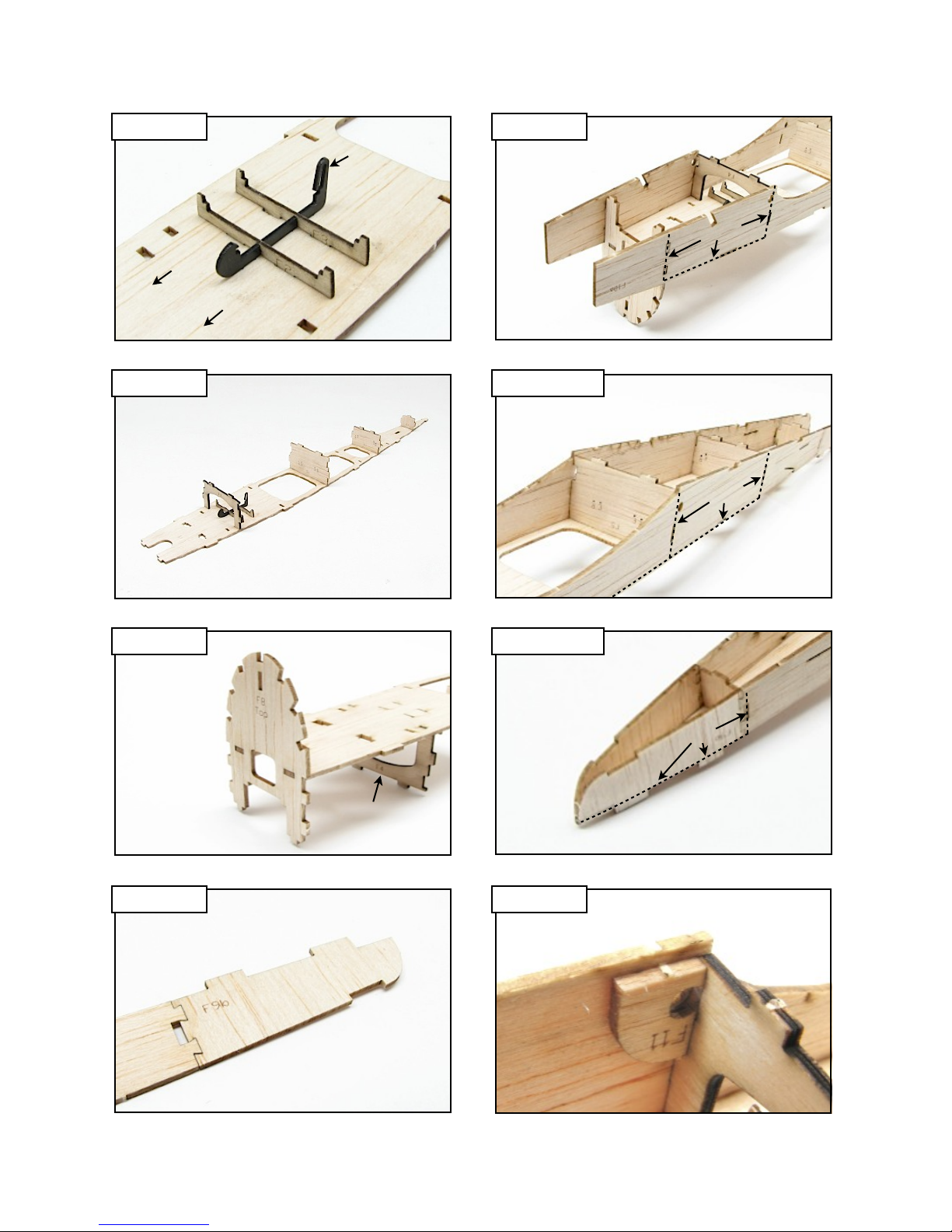
1. Central Crutch - Lay F1 (sheet 01/10, 1/16 in. balsa) on the work surface with the etched
side facing up. Fit F2 and F3 (sheet 09/10, 1/32 in. ply) to the nylon receiver clip supplied in
your hardware bag to make the receiver tray. Fit the receiver tray to the four slots in the
center just forward of the large openings in F1. Bond with thin CA.
2. Fit and tack glue formers F4 (sheet 10/10, 1/16 in. ply) F5, F6, and F7 (sheets 01 and
02/10, 1/16 in. balsa) to F1. F4 goes in the slots immediately forward of the receiver tray.
F5 fits the crosspiece between the first and second large openings. F6 fits immediately
behind the last large opening. F7 fits in the last pair of slots near the rear of F1.
3. Turn the assembly right side up so that the formers are underneath F1. Fit and tack glue
former F8 (sheet 02/10, 1/16 in. balsa) to the front of F1, oriented with the top of F8 pointing
up.
4. Fuselage Sides - Fit and bond F9a (sheet 01/10, 1/16 in. balsa) to F9b (sheet 01/10, 1/16
in. balsa), and F10a (sheet 01/10, 1/16 in. balsa) to (sheet 02/10, 1/16 in. balsa).
5. Turn the central crutch assembly up side down again, so that the formers are on top. Fit
fuselage side F9 to the left side of the assembly, tack gluing it to F1 and formers F4 and F5
only. Repeat this step to fit and tack glue F10 to the right side of the assembly. Continue
working toward the rear of the assembly, tacking the fuselage sides to formers F5 and F6.
Pull the rear of the fuselage sides together, tacking to former F7 and the rear of F1.
Square the assembly on a flat surface, with the top of former F8 hanging over the edge of
the work surface. Final bond all parts together with thin CA.
6. Fit parts F11 (sheet 01/10, 1/16 in. balsa) to the front of former F4, against each fuselage
side, and bond with thin CA.
Pacemaker 100 - Build Instructions © 2016 Stevens AeroModel, all rights reserved.! Page 8
Page 9
Build Instructions
Step 1
Bottom View
Front
Step 2
F4
F5
Long Arm
F1
F3
F2
F6
F7
Bottom View
Step 5
F9
Step 5 Cont.
F9
F5
Bond
F10
Bottom View
F6
Bond
F10
Bottom View
Step 3
Top Vi ew
F8
To p
F1
Formers
Underneath
Step 5 Cont.
Step 4 Step 6
F9b
F9a
F9
Bond
Bottom View
Bottom View
F11
F4
Pacemaker 100 - Build Instructions © 2016 Stevens AeroModel, all rights reserved.! Page 9
Page 10

Fuselage (continued)
Build Instructions
□
□
□
□
□
□
□
□
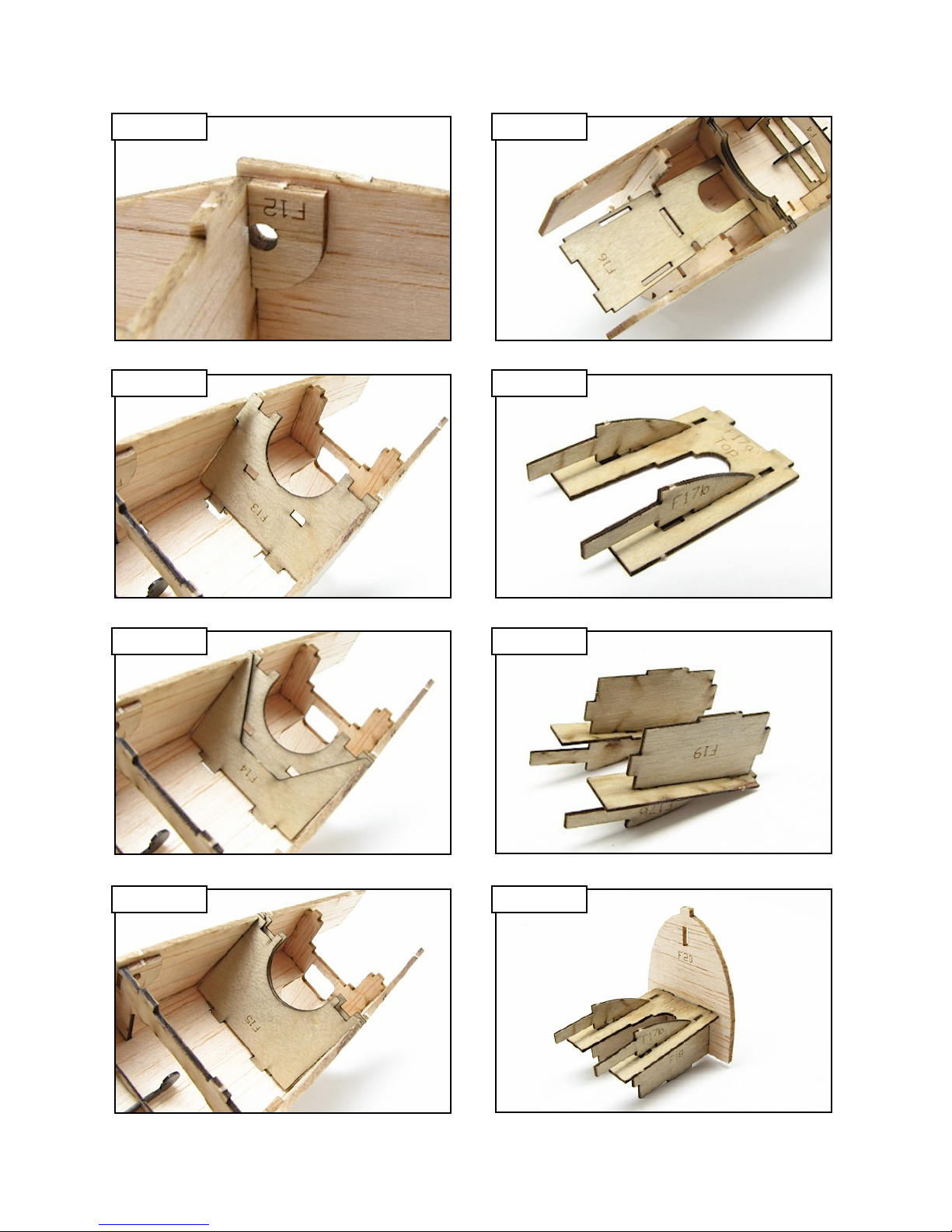
7. Fit parts F12 (sheet 01/10, 1/16 in. balsa) to the rear of former F5, against each fuselage
side, and bond with thin CA.
8. Landing Gear Pocket - Fit F13 (sheet 09/10, 1/32 in. ply) to the notches on the fuselage
sides and the large slots in F1. These notches and slots are oversized to accommodate the
other parts of the landing gear pocket, F13 will rest in the front portion of these openings.
9. Fit F14 (sheet 09/10, 1/32 in. ply) into the same openings, immediately behind and flush
against F13.
10. Fit F15 (sheet 09/10, 1/32 in. ply) into the same openings, immediately behind and flush
against F14. Make sure that all three parts are fully seated, then wick thin CA around the
edges of the parts to bond them together and to the fuselage. Make sure that no glue gets
into the pocket itself.
11. Battery Tray - Fit and bond the battery tray F16 (sheet 09/10, 1/32 in. ply) to the slots in
F13 and the tabs on former F8.
12. Motor Mount - Lay F17a (sheet 09/10, 1/32 in. ply) on the work surface with the side
etched ‘Top’ facing up. Fit and bond two F17b’s to the slots in each side of F17a.
13. Turn the assembly up side down. Fit and bond parts F18 and F19 (sheet 09/10, 1/32 in.
ply) to the bottom of F17a.
14. Fit and bond the assembly to former F20.
Pacemaker 100 - Build Instructions © 2016 Stevens AeroModel, all rights reserved.! Page 10
Page 11
Build Instructions
Step 7
Step 8
F5
F13
F12
Bottom View
F9
F8
Bottom View
Step 11
Step 12
F16
F17b
Bottom View
F17a
To p
F17b
Step 9
F14
Bottom View
Step 13
Step 10 Step 14
F15
F18
F19
Bottom View
F20
Pacemaker 100 - Build Instructions © 2016 Stevens AeroModel, all rights reserved.! Page 11
Bottom View
Page 12

Fuselage (continued)
Build Instructions
□
□
□
□
□
□
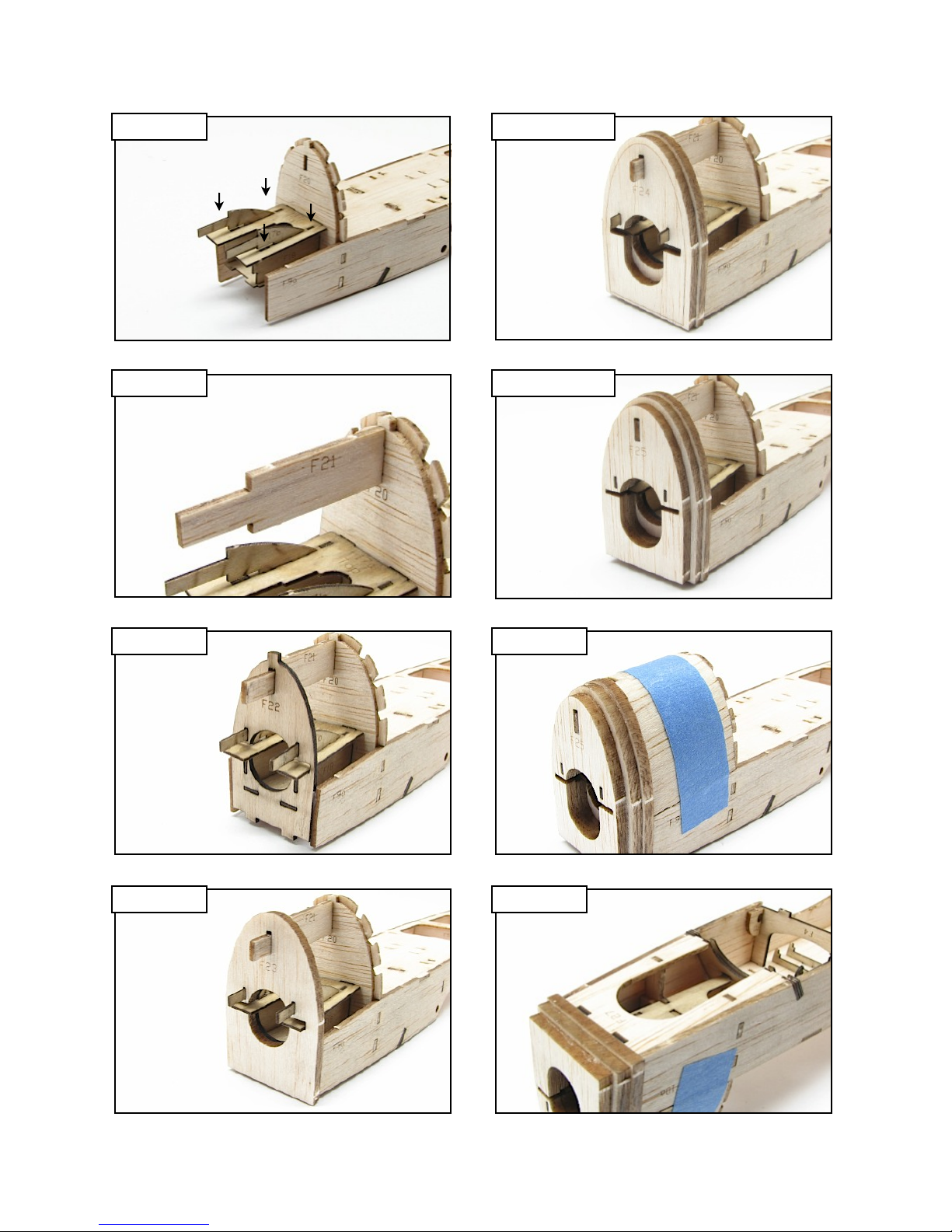
15. Slide the completed motor mount assembly down into the nose of the model, Fitting the
tabs at the base of F18, F19, and F20 into the slots in the battery tray F16. Make sure that
F20 is flush against the front of former F8, then bond the motor mount assembly to the
fuselage with thin CA.
16. Cowling - Fit and bond the cowling spine F21 (sheet 01/10, 1/16 in. balsa) to the slot at the
top of formers F8/F20, oriented so that the long tab on F21 points forward.
17. Slide former F22 (sheet 10/10, 1/16 in. ply) onto the long tabs on F17b and F21, and over
the front of F17a, fitting it to the tabs on F18, F19, and the battery tray F16.
18. In order, slide F23, F24, and F25 (sheet 08/10, 1/8 in. balsa) onto the tabs on F17a and
F21. Make sure that they are flush against each other and former F22, then wick thin CA
around the edges to bond.
19. Locate the cowl sheeting F26 (sheet 02/10, 1/16 in. balsa). Moisten one side with glass
cleaner, and allow it to soak in for a minute or two. Wrap F26 - moist side out - around
formers F20 and F22, holding it in place with low tack masking tape until dry. When F26 is
completely dry, remove the tape, and bond it to the fuselage with thin CA.
20. Fuselage Bottom - Turn the fuselage up side down, and fit the forward fuselage bottom
F27 (sheet 01/10, 1/16 in. balsa) to formers F8, F22, and F13 of the landing gear pocket.
Bond with thin CA.
Pacemaker 100 - Build Instructions © 2016 Stevens AeroModel, all rights reserved.! Page 12
Page 13
Build Instructions
Step 15
Step 16
Step 18 Cont.
F20
F24
Step 18 Cont.
F25
F21
F20
Step 17
F22
Step 19
Step 18 Step 20
Bottom View
F23
F26
F27
Pacemaker 100 - Build Instructions © 2016 Stevens AeroModel, all rights reserved.! Page 13
Page 14

Fuselage (continued)
Build Instructions
□
□
□
□
□
□
□□
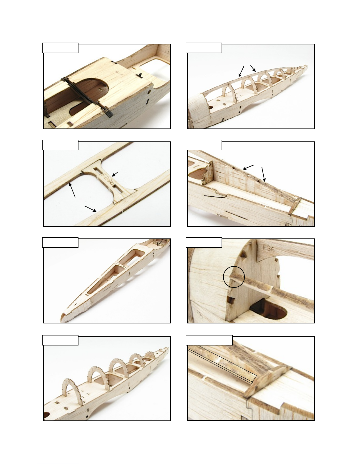
21. Fit and bond F28 (sheet 02/10, 1/16 in. balsa) between the fuselage side, former F4, and
F15 of the landing gear pocket.
22. Assemble the rear fuselage bottom by fitting F29b into the middle of F29a (sheet 03/10,
1/16 in. balsa), and bonding with thin CA.
23. Fit the completed F29 to the rear of the fuselage, bonding it to the fuselage sides and
formers F5, F6, and F7.
24. Fuselage Top - Turn the fuselage right side up. Fit and tack glue the upper formers F30
through F35 (sheet 04/10, 1/16 in. balsa) in the positions shown. Note: F35 shares a
common slot in F1 with former F7 below.
25. Fit and bond the spine F36 (sheet 05/10, 3/32 in. balsa) into the notch at the top of each
former, and the slots in F1 between formers F34 and F35.
26. Position and bond one F37 (sheet 01/10, 1/16 in. balsa) on each side of the rear of F36
between formers F34 and F35.
27. Stringers - Fit one end of a length of 3/32 in. x 1/8 in. balsa strip stock (sheet 05/10, 3/32
in. balsa) into the middle notch on the left side of former F8. Fit the stringer in the middle
notch in each former, working your way aft. Trim the stringer to rest flush against the front
face of former F35. Bond the stringer to each former with thin CA. Repeat this step to
install the middle stringer on the right side of the fuselage.
Pacemaker 100 - Build Instructions © 2016 Stevens AeroModel, all rights reserved.! Page 14
Page 15
Build Instructions
Step 21
Step 22
Step 25
F36
F28
Bottom View
Step 26
F37
F29b
F37
F29a
Step 23
Step 24
F30
F31
F32
Bottom View
F34
F33
F35
Step 27
Middle
Notch
Step 27 Cont.
F8
F35
Pacemaker 100 - Build Instructions © 2016 Stevens AeroModel, all rights reserved.! Page 15
Page 16

Fuselage (continued)
Build Instructions
□□
□□
□□
□
□
□
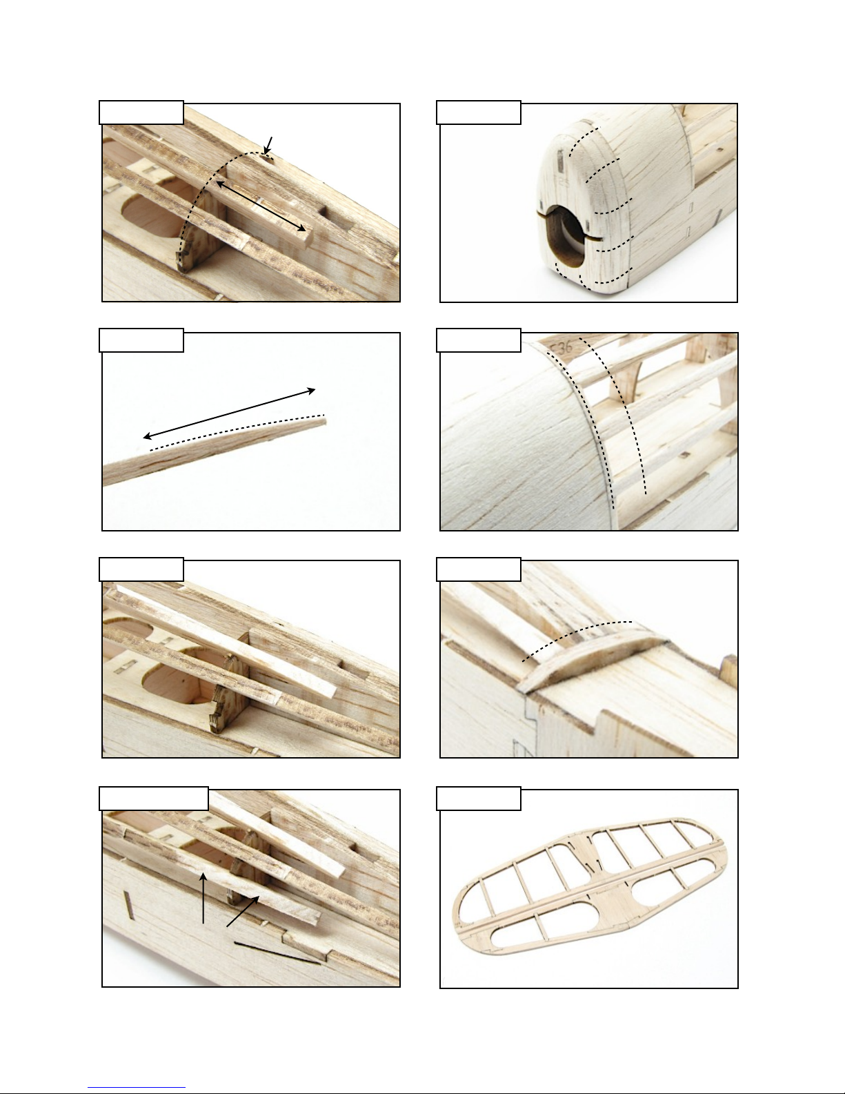
28. Follow the same procedure to install the upper stringer to the top notch on each side of the
formers. Trim the upper stringer 1/2 in. beyond former F34.
29. Remove the stringer, and sand the top of last inch at the rear of the stringer to a tapering
arc. This will allow the stringer to neatly ‘disappear’ beneath the covering at this former.
30. Reinstall the stringer, ensuring that the sanded surfaces faces out, and bond with thin CA.
Repeat steps 28 through 30 to install the bottom stringer in the lowest notch on the sides of
the formers.
31. Final Sanding - Lightly sand the completed fuselage, removing any excess glue and
smoothing the joints between parts. Radius the front of the cowl sides, top, and bottom as
shown.
32. Sand the stringers to flow smoothly into the cowl. Continue sanding the stringers, removing
the high spots so that the covering will lie smoothly.
33. Sand the rear of the stringers to flow smoothly into former F35.
Set the completed fuselage aside until needed later in the instructions.
Tail Surfaces
□
34. Horizontal Stabilizer and Elevator - Build these surfaces over the plan on the detail sheet,
from parts H1 through H7 (sheet 05/10, 3/32 in. balsa) for the stabilizer, and E1 through E5
(sheet 05/10, 3/32 in. balsa) for the elevator, bonding with thin CA.
Pacemaker 100 - Build Instructions © 2016 Stevens AeroModel, all rights reserved.! Page 16
Page 17
Build Instructions
Step 28
Step 29
Step 31
F34
1/2 in.
Step 32
1 in.
Step 30
Step 30 Cont.
Lower
Stringer
Step 33
F35
Step 34
Pacemaker 100 - Build Instructions © 2016 Stevens AeroModel, all rights reserved.! Page 17
Page 18

Tail Surfaces (continued)
Build Instructions
□
□
□
Wing
□
□
□
□
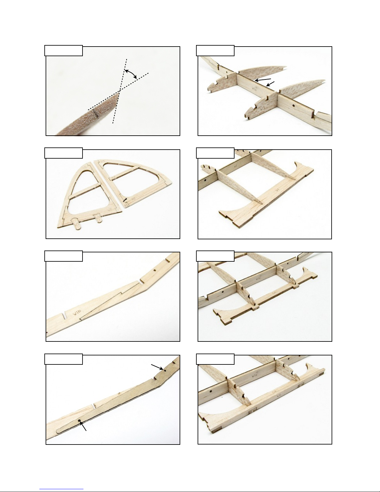
35. Align the leading edge of the elevator with the edge of the work surface. Using a sanding
block or stick, sand a 45 degree bevel along the entire leading edge. This bevelled side will
now be referred to as the ‘bottom’ of the elevator.
36. Vertical stabilizer and rudder - Build these surfaces over the plan on the detail sheet, from
parts V1 through V6 (sheet 06/10, 3/32 in. balsa) for the stabilizer, and R1 through R4
(sheet 06/10, 3/32 in. balsa) for the rudder, bonding with thin CA.
37. Not shown - refer to photo #35. Align the leading edge of the rudder with the edge of the
work surface, oriented so that the right side of the rudder faces up. Using a sanding block
or stick, sand a 45 degree bevel along the entire leading edge.
Lightly sand the completed tail surfaces and set them aside until they are needed later in
the instructions.
38. Center Section - Lay W1a (sheet 03/10, 1/16 in. balsa) on a flat work surface. Fit and
bond one W1b (sheet 03/10, 1/16 in. balsa) to each end of W1a.
39. Align W2 (sheet 09/10, 1/32 in. ply) over W1, using the alignment holes as guides. Bond
with thin CA.
40. Fit two ribs W3 (sheet 04/10, 1/16 in. balsa) to the two slots in the center of the spar. Make
sure that the ribs and spar are oriented so that W2 is behind W1.
41. Fit and bond the center section trailing edge W4 (sheet 06/10, 3/32 in. balsa) to the rear of
ribs W3.
□
□
42. Fit and bond the leading edge web W5 (sheet 06/10, 3/32 in. balsa) to the front of ribs W3.
43. Fit and bond the leading edge W6 (sheet 05/10, 3/32 in. balsa) to the front of W5.
Pacemaker 100 - Build Instructions © 2016 Stevens AeroModel, all rights reserved.! Page 18
Page 19
Build Instructions
Step 35
Step 36
Step 40
45 deg.
W2 Behind
W3
To p
W3
Bottom
Step 41
W3
W3
W4
Step 38
W1a
W1b
Step 39 Step 43
Alignment Hole
Alignment Hole
W2
F1
Step 42
W5
W5
W6
Pacemaker 100 - Build Instructions © 2016 Stevens AeroModel, all rights reserved.! Page 19
Page 20

Wing (continued)
Build Instructions
□
□
□
□
□
□
□
□
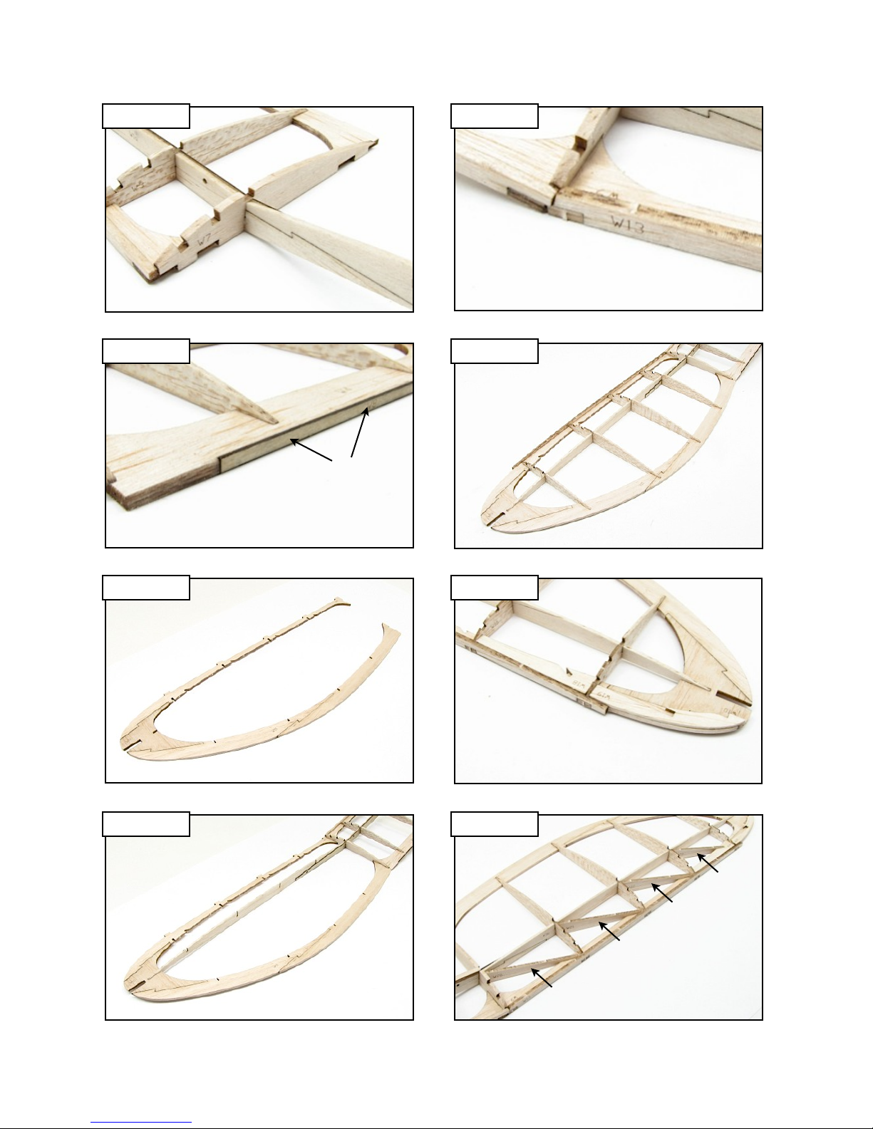
44. Fit one rib W7 (sheet 07/10, 3/32 in. balsa) to the notches in the spar outboard of ribs W3,
and to the leading and trailing edges. Square the center section on a flat surface, and final
bond all parts together with thin CA.
45. Fit and bond W8 (sheet 09/10, 1/32 in. ply) into the recess in the trailing edge W4.
46. Outer Panels - Assemble the wing outlines over the plan on the detail sheet from parts W9
through W12 (sheet 06/10 and 07/10, 3/32 in. balsa), and bond with thin CA.
47. Fit and bond the wing outlines to ribs W7 and the tips of the spar.
48. Fit and bond the leading edge W13 (sheet 05/10, 3/32 in. balsa) to the front of W9.
49. Fit and bond ribs W14 through W17 (sheet 04/10, 1/16 in. balsa) to the wing panel - refer to
the plan on the detail sheet for the correct location of each rib.
50. Fit the wing tip doubler W18 (sheet 03/10, 1/16 in. balsa) between ribs W16 and W17, flush
against W13. Align doubler W19 (sheet 03/10, 1/16 in. balsa) over W9, flush against rib
W17 and the leading edge W13.
51. Fit and bond the diagonal braces W20 through W23 (sheet 03/10, 1/16 in. balsa) between
the ribs, spar, and leading edge. Refer to the plan on the detail sheet for the correct
location of each brace.
Pacemaker 100 - Build Instructions © 2016 Stevens AeroModel, all rights reserved.! Page 20
Page 21
Build Instructions
Step 44
Step 45
Step 48
W3
W7
W13
Step 49
W4
W14
W15
W8
W16
W17
Step 46
W9
W12
W10
W11
Step 50
Step 47 Step 51
W18
W19
W23
W22
W21
W20
Pacemaker 100 - Build Instructions © 2016 Stevens AeroModel, all rights reserved.! Page 21
Page 22

Wing (continued)
Build Instructions
□□
□
□
□
□
□
□
□
□
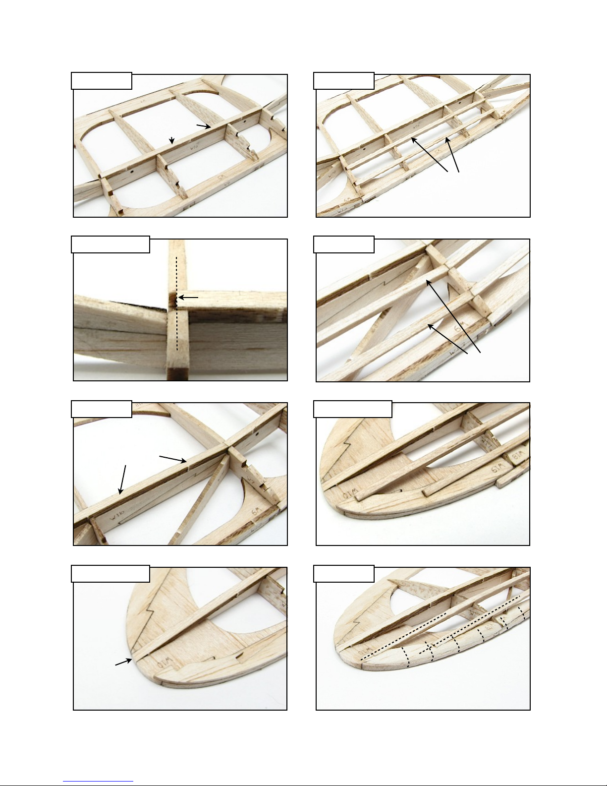
52. Turbulator Spars - Cut a length of 1/8 in. x 3/32 in. strip stock (sheet 05/10, 3/32 in. balsa)
to fit between ribs W7 spanning the center section. Trim the ends so that they end down
the center line of the ribs. Lay the spar strip flat (1/8 in. side facing up) in the notches over
the main spar, and bond to the ribs and spar with thin CA.
53. Fit one end of a full length of 1/8 in. x 3/32 in. strip stock (sheet 05/10, 3/32 in. balsa) to the
notch in rib W7, butted up against the center section turbulator spar. Make sure that the
strip is lying flat (1/8 in. side facing up) then bond to rib W7 and the main spar between ribs
W7 and W14. Proceed down the wing toward the tip, fitting and bonding the spar strip to
each rib and the spar. Fit the end of the spar strip into the notch at the tip of W10, and trim
flush with the wing tip.
54. Repeat step 52 to install the two front turbulator spars in the center section, this time
standing them up on edge (3/32 in. side facing up).
55. Repeat step 53 to install the two front turbulator spars in each wing panel. Make sure that
the spar strips are standing on edge (3/32 in. side facing up). Trim the ends to rest in the
recesses of the wing tip doubler W19.
56. Final Sanding - Lightly sand the completed wing, removing any excess glue and smoothing
the joints between parts. Round the leading edge and front of the wing tip. Leave the
trailing edge square. Sand the ends of the turbulator spars to flow smoothly into the wing
tip.
Pacemaker 100 - Build Instructions © 2016 Stevens AeroModel, all rights reserved.! Page 22
Page 23
Build Instructions
Step 52
1/8 in. x 3/32 in.
Step 52 Cont.
Step 54
Lying Flat
3/32 in. x 1/8 in.
On Edge
Step 55
W7
Centered
3/32 in. x 1/8 in.
On Edge
Step 53
1/8 in. x 3/32 in.
Lying Flat
Step 53 Cont.
Flush
Step 55 Cont.
W7
W19
Step 56
W10
Pacemaker 100 - Build Instructions © 2016 Stevens AeroModel, all rights reserved.! Page 23
Page 24

Covering
Build Instructions
□
□
□
□
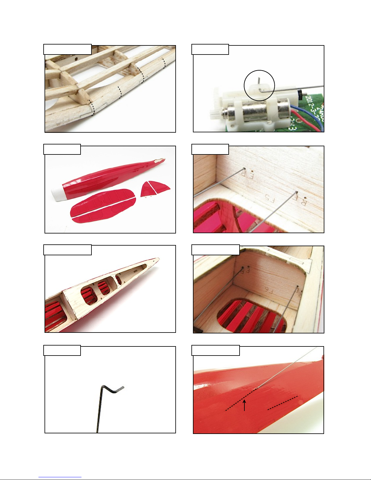
57. Cover your model with a high quality, light weight iron on material. We recommend
AeroLite, available at stevensaero.com.
Fuselage - Cover the sides up to the second (middle) stringer with one piece of material.
Trim the excess with a sharp razor blade. Cover the space between the second (middle)
stringer and the central keel with a separate piece for each side of the model. Cover the
nose and the bottom forward of the radio compartment. Leave the rear of the fuselage
bottom uncovered, to allow access for installing the push rods. This area will be covered in
a later step.
Wing - Cover the bottom in three pieces, the center section first, then the outer panels.
Cover the top of the center section next. The outer panels may, with care, be covered with
one pice of material, however, you may find it easier to cover from the main spat back with
one piece, and the front forward of the spare with a separate piece of material.
Tail Surfaces - Cover both sides of each surface. Leave the tabs at the base of the vertical
stabilizer uncovered.
Push Rods and Receiver
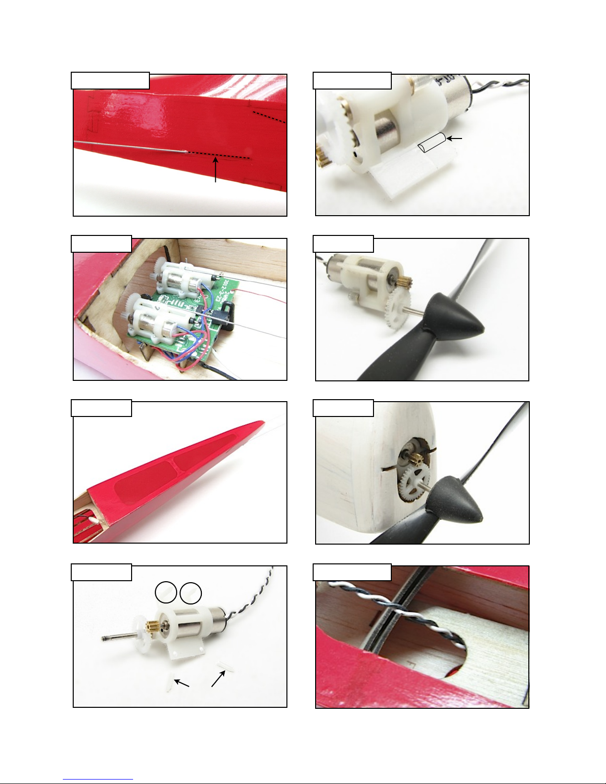
58. Refer to the Push Rod Detail on the detail sheet, and make a ‘snake’ bend in on end of
each of the .015 in. wire push rod material supplied in your kit.
59. Connect the ‘snake’ bend to the servo tabs on the receiver brick. Note: the tabs have three
different size holes. Connect the push rods to the middle hole.
60. Pass the push rods through formers F5 and F6. The rudder push rod (servo nearest the
antenna on the receiver) goes through the hole on the left side of the formers marked ‘R’.
The elevator push rod goes through the holes on the right side of the formers marked ‘E’.
Slit the covering over the upper exit slot on the left side of the model, and pass the rudder
push rod through it. Slit the covering over the lower exit slot on the right side of the
fuselage and pass the elevator push rod through it.
Pacemaker 100 - Build Instructions © 2016 Stevens AeroModel, all rights reserved.! Page 24
Page 25
Build Instructions
Step 56 Cont.
Step 57
Step 59
Step 60
Middle Hole
R
Bottom View
F5
E
Step 57 Cont.
Step 58
Bottom View
Step 60 Cont.
Step 60 Cont.
R
Upper
Exit Slot
Bottom View
F6
E
Rudder
Left Side
Pacemaker 100 - Build Instructions © 2016 Stevens AeroModel, all rights reserved.! Page 25
Page 26

Build Instructions
Push Rods and Receiver (continued)
□
□
61. Install the receiver in the receiver tray by first fitting the front edge of the circuit board into
the notch in the short arm of the nylon clip, then press down on the rear of the board until it
snaps under the long arm of the clip.
62. You may now cover the bottom rear of the fuselage.
Motor and Propellor
□
□
□
63. Remove the spikes from the bottom of the mounting tabs on the gearbox of the
recommended motor (PKZ3624) and sand the tabs smooth. Turn the motor over, and
remove the bump at the rear of each tab, using a sharp razor blade, then sand the tab
smooth.
64. Install the recommended propellor (EFL9051) by threading it onto the output shaft of the
gearbox.
65. Turn the motor up side down (small gear on top, big gear on the bottom), and feed the
motor lead through the cowl and down through the opening in the battery tray F16. Press
the motor into the nose of the model until it is fully seated in the motor mount. Friction
should be enough to retain the motor, but you may apply a small drop of medium CA at the
front of each mounting tab for added security.
Pacemaker 100 - Build Instructions © 2016 Stevens AeroModel, all rights reserved.! Page 26
Page 27
Build Instructions
Step 60 Cont.
Right Side
Step 61
Lower
Exit Slot
Bottom View
Step 63 Cont.
Bump
Step 64
Step 62
Bottom View
Step 63
Bottom View Bottom View
Spikes
Spikes
Step 65
Step 65 Cont.
F16
Pacemaker 100 - Build Instructions © 2016 Stevens AeroModel, all rights reserved.! Page 27
Page 28

Tail Surfaces
Build Instructions
□
□
□
□
□
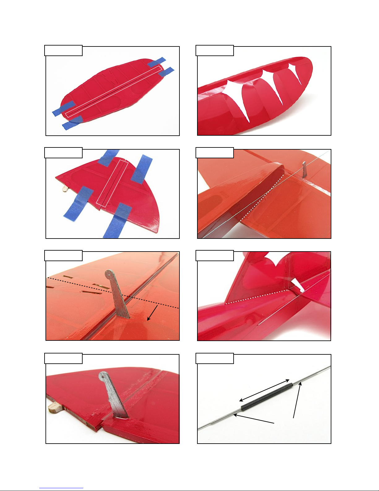
66. Hinging - Using low tack masking tape, secure the horizontal stabilizer and elevator to the
work surface. Make sure there is a 1/64 in. gap between the surfaces, and that the elevator
is place with the bevelled side down. Slice a length of 1/2 in. wide clear tape down the
center, leaving your with a strip /4 in. wide. Apply this strip of tape over the gap between
the surfaces to create a hinge, and trim off the excess. Remove the surfaces, and flex the
elevator back and forth, making sure that it moves freely with no binding. If there is
resistance of any kind, remove the hinge tape and repeat the hinging process, this time
increasing the gap between the surfaces slightly.
67. Follow the procedure in step 66 to hinge the rudder to the vertical stabilizer, orienting the
parts on the work surface with the left side facing up (bevelled side of elevator facing down).
68. Control Horns - Lay the horizontal stabilizer on the work surface with the bevelled side of
the elevator facing up. Slit the covering over the control horn slot on the right side of the
elevator. Press the control horn etched ‘E’ (sheet 09/10, 1/32 in. ply) into the slot, oriented
so that the hole in the end of the control horn is directly over the hinge line. Bond the horn
to the elevator with medium CA.
69. Follow the procedure in step 68 to mount the control horn ‘R’ (sheet 09/10, 1/32 in. ply) to
the left side of the rudder.
70. Graphics - If you have purchased the pre-cut graphics, available at stevensaero.com, now
is the time to apply them. Refer to the plans on the detail sheet for the location of the
graphics. Spray the are of the model where the graphic is to be applied with glass cleaner.
This will allow you to ‘float’ the graphic onto the covering, making it easy to position the
graphic properly. When you are satisfied with the placement, Scrape the graphic with a
credit card or similar straight edged surface to squeegee the glass cleaner from under the
graphic. Wipe up the excess glass cleaner from around the graphic, and allow it to dry
thoroughly. Do not apply heat! When dry, the graphic will be firmly affixed to the covering.
□
□
□
71. Mounting - Remove the covering over the four slots on the bottom of the horizontal
stabilizer. Mount the stabilizer to the four tabs at the rear of the fuselage. View the model
from the front and rear, making sure that the stabilizer is perpendicular to the fuselage
sides. Bond the stabilizer by running a small bead of medium CA along the seam where it
meets the fuselage.
72. Remove the covering over the two slots at the rear of the central spine on top of the
fuselage. Fit the tabs at the base of the vertical stabilizer into the slots. Run a small bead
of medium CA along the seam between the stabilizer and fuselage on both sides of the
stabilizer.
73. Push Rod Connections - Cut a 3/4 in. length of the heat shrink tubing supplied in your kit,
and slide it over two scrap pieces of .015 in. wire. Shrink the tubing over the wires using a
heat gun or warm soldering iron, and allow to cool. Remove the pre-shrunk tubing and cut
it in half, leaving you with two pieces 3/8 in. long.
Pacemaker 100 - Build Instructions © 2016 Stevens AeroModel, all rights reserved.! Page 28
Page 29
Build Instructions
Step 66
Step 67
Ta pe
Ta pe
Bevelled
Side Down!
Bevelled
Side Down!
Step 70
See Detail
Sheet for
Locations
Step 71
Bond
Left Side
Step 68
Bottom View
Center
Right Side
Step 72
Step 69 Step 73
Bottom View
Bond
Heat Shrink Tube
3/4 in.
Left Side
Pacemaker 100 - Build Instructions © 2016 Stevens AeroModel, all rights reserved.! Page 29
Two Pieces
.015 in. Wire
Page 30

Tail Surfaces (continued)
Build Instructions
□
□
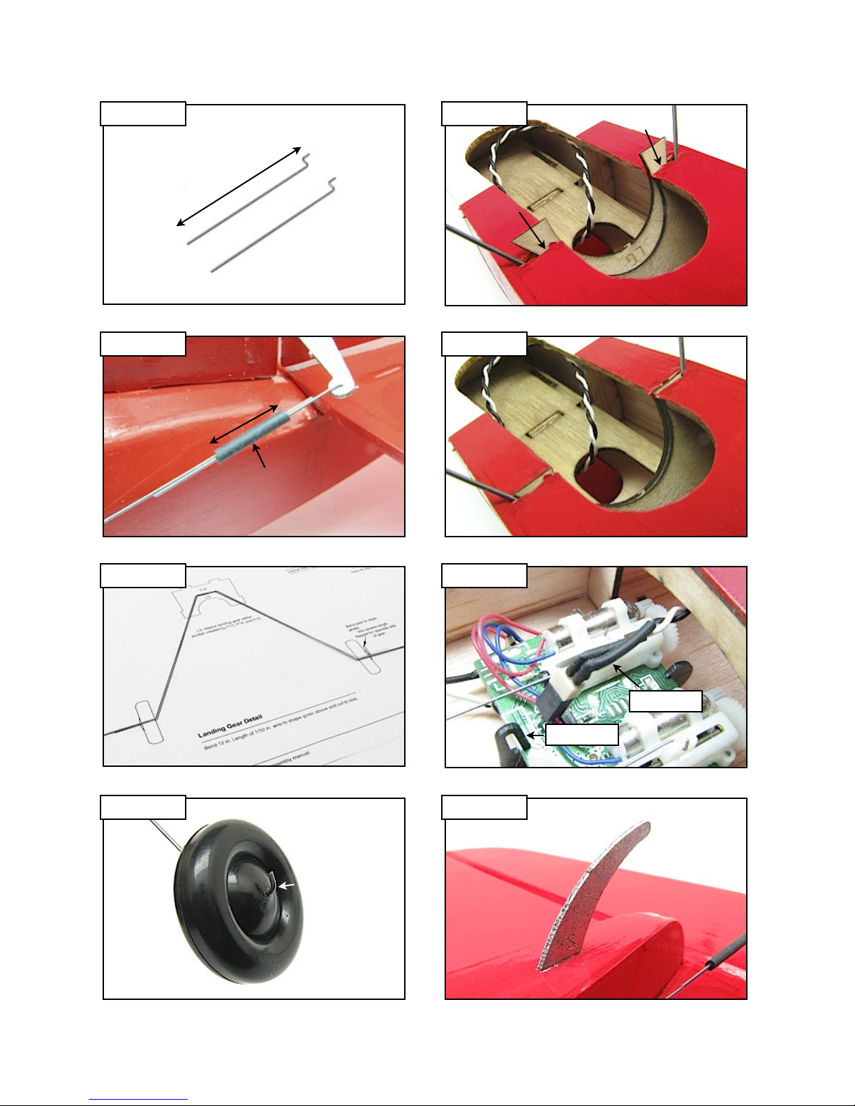
74. Refer to the Push Rod Detail on the detail sheet, and make up two “Part B’s” from .015 in.
wire. Trim the wire to and overall length of 3/4 in.
75. Fit “Part B” to the control horn, then connect it to the push rod with a 3/8 in. length of the
pre-shrunk tubing. You may now slide the wires back and forth within the tube to center the
control surface. When you are satisfied that the control surface is centered, apply a small
drop of medium CA to each end of the tube to secure.
Landing Gear
□
□
□
□
□
76. Bend the landing gear over the pattern on the detail sheet, using the 1/32 in. wire supplied
in your kit. Proceed carefully, as accuracy is critical for a proper fit.
77. Mount the supplied wheels onto the landing gear wire. Bend the axle up 90 degrees to
retain the wheels, and trim off the excess wire.
78. Slit the covering over the landing gear pocket, and press the wire into the pocket. Press
part LG (sheet 09/10, 1/32 in. ply) into the pocket until it is flush with the fuselage bottom.
Wick thin CA along the pocket and the point where the landing gear wire exits the fuselage
to secure.
79. You may now connect the motor lead to the socket at the rear of the receiver circuit board.
Orient the lead so that the black wire is in the center of the board, nearest the long arm of
the receiver clip.
80. Slit the covering over the slot at the bottom rear of the fuselage. Press the tail skid TS
(sheet 09/10, 1/32 in. ply) into the slot and secure with medium CA.
Pacemaker 100 - Build Instructions © 2016 Stevens AeroModel, all rights reserved.! Page 30
Page 31
Build Instructions
Step 74
Step 75
3/4 in.
3/8 in.
Heat Shrink
Tube
.015 in. Wire
Step 78
LG
Bottom View
Step 78
Flush
Flush
Bottom View
Step 76
1/32 in. Wire
Step 79
Bottom View
Step 77 Step 80
Bottom View
90 deg. Bend
Black Wire
Long Arm
TS
Pacemaker 100 - Build Instructions © 2016 Stevens AeroModel, all rights reserved.! Page 31
Page 32

Details
Build Instructions
□
□
□
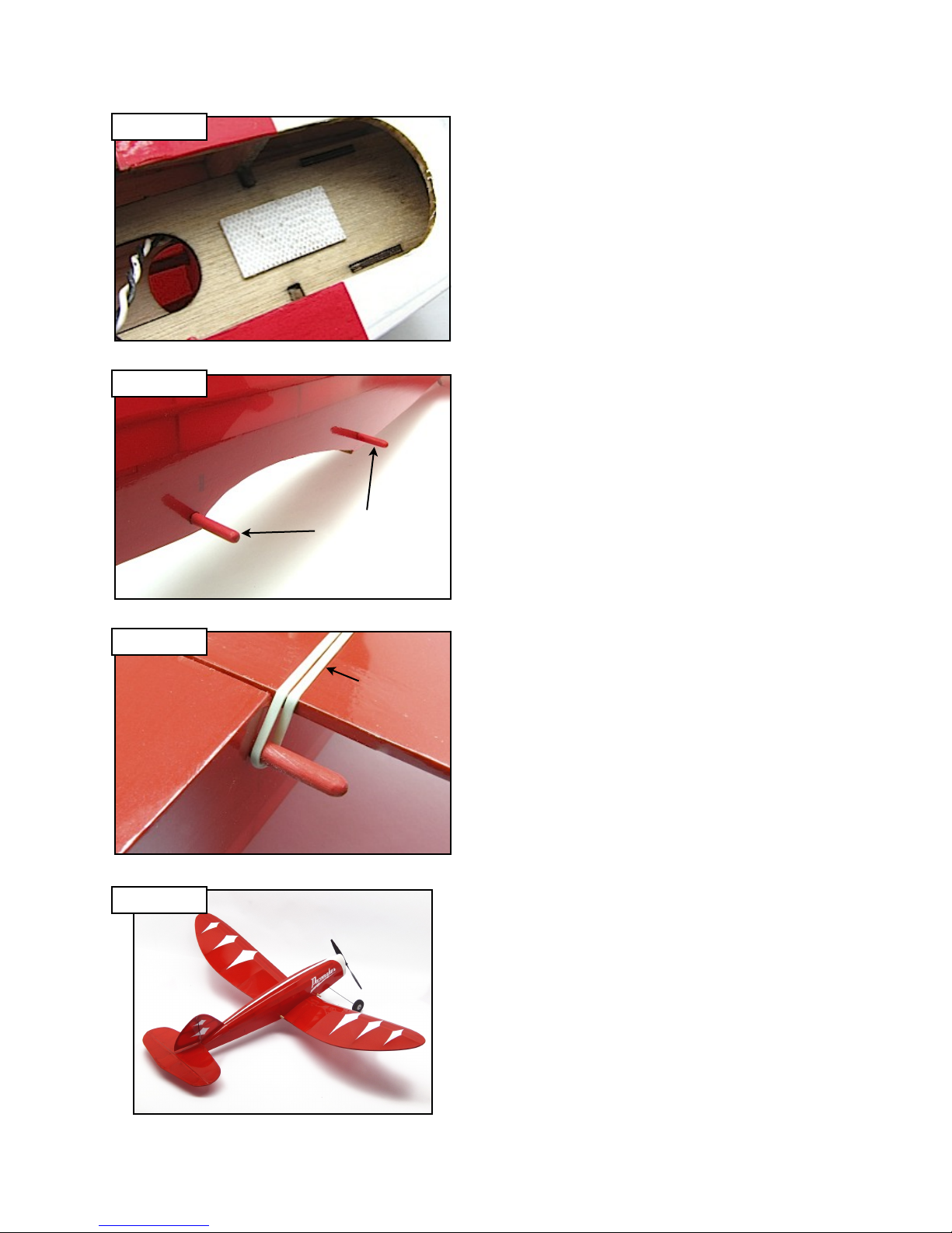
81. Apply a small piece of self adhesive Velcro (PKZ1039) to the battery tray to secure the
battery.
82. Locate the two 1/8 in. x 2 in. dowels supplied in your kit. Sand the ends round, and paint
them to match your color scheme. Remove the covering over the hole in the fuselage sides
in front of and behind the wing saddle. Slide the dowels through the holes, centering them
so that an equal length protrudes from each side of the fuselage. Wick thin CA around the
point where the dowels exit the fuselage to secure.
83. Mount the wing to the fuselage. Retain the wing by looping one or two #16 rubber bands
(supplied in your kit) around the dowels and under the wing.
Congratulations!
Your Stevens AeroModel Pacemaker UM is now complete! Please proceed to the Setup
and Preflight sections to prepare your model for it’s first flights.
Pacemaker 100 - Build Instructions © 2016 Stevens AeroModel, all rights reserved.! Page 32
Page 33
Step 81
Step 82
Build Instructions
Velcro
Bottom View
1/8 in. x 2 in.
Dowels
Step 83
Complete
#16
Rubber Band
Bottom View
Pacemaker 100 - Build Instructions © 2016 Stevens AeroModel, all rights reserved.! Page 33
Page 34

Build Instructions
Setup
DO NOT ATTEMPT FLIGHT IF THE WINGS ARE WARPED. Inspect the wings for any warps that may
have occurred when covering the model, or while the model was in storage. Remove all warps before
flight. Lack of aileron control on this model will make flying with a warped wing difficult.
Rudder - Center the rudder. Then, set the direction, rate of travel, and dampening (expo) of the control.
The rudder servo should be controlled by the aileron channel on your radio, as the rudder on this model
also controls the roll of the aircraft. The rudder should follow aileron stick travel, i.e., moving the aileron
stick to the right should move the rudder to the right.
Elevator - Center the elevator. Then, set the direction, rate of travel, and dampening (expo) of the
control. The elevator will be controlled by the elevator channel on your radio. Moving the elevator stick
back should move the elevator up. Moving the elevator stick forward should move the elevator down.
The Pacemaker UM was designed to be a very docile flyer. We set up our flight controls with fairly
minimal throws. With the push rods connected, per the instructions in this manual, set the control throws
as follows:
Rudder Travel
+/- 12 degrees
Elevator Travel
+/- 15 degrees
Preflight
It is recommended that you have an experienced pilot assist you with preflighting your new model.
Just like having someone proofread something you’ve written, having a second fresh set of eyes inspect
your final product is often helpful in avoiding disaster.
While not a thorough preflight check, listed below are some of the major items that you should consider
checking when developing your own preflight check list. Get in the habit of always preflighting your
models before every flight.
Weight and Balance - Check the balance of your model (C.G., center of gravity). For proper
performance, the model should balance at the main spar. Use your right and left index fingers to suspend
the model from below, at the wing tips. If the horizontal stabilizer appears to hang level, the model is
properly balanced and ready to fly. If the nose or tail of the model hang down, move the battery forward
and backward to make subtle changes, or add clay ballast to the nose or tail as required to obtain proper
balance.
Check Weather - The first flight should be outdoors in zero wind conditions. The Pacemaker UM can fly
in winds up to 5 miles per hour.
Inspect the Airframe - Always check for warps and obvious signs of wear or damage. Do not fly a
warped or damaged model.
Inspect Control Surfaces - Always check control surfaces for center, proper direction of travel, rate of
throw, secure push rod connections, hinges, and receiver/servo mounting hardware.
Check Wing Attachment Points - Always make sure you inspect for damage and wear. Make sure that
the wing and rubber bands, if applicable, are properly attached.
Inspect Battery - Always use a freshly-charged battery. Never begin a flight with a partially-charged
or damaged battery.
Clear Prop - Stay clear of the prop arc, when applying power to the model.
Pacemaker 100 - Build Instructions © 2016 Stevens AeroModel, all rights reserved.! Page 34
Page 35

Build Instructions
Preflight (continued)
Range Check Radio - Follow the manufacturer’s instructions for performing a radio range check.
Check for Traffic - Proceed to the flight line (with your mentor/instructor if you are a novice pilot) and look
for other traffic. If the runway is clear, and no one is in the pattern to land, loudly announce your
intentions to take off. Remember, all aircraft on the ground must yield the runway to those landing.
Go Flying - Point the model into the wind (if present) and steadily advance the throttle to full power.
Use rudder control to correct track while on the ground. Within several feet, the model should be
airborne. Fly the model to a comfortable “1 to 2 mistakes high altitude”, reduce throttle to stop the climb,
then trim the model for straight-and-level flight at a comfortable cruise speed. The Pacemaker UM
typically cruises at just over one-half throttle.
Setup for Landing - Clearly announce your intentions to land. Make all landings into the wind, using
rudder and elevator controls. Crosswind landings should be avoided until you are comfortable with the
model’s in-flight behavior.
Congratulations!
Once you’ve completed your first flights, you will have noticed that the Stevens AeroModel
Pacemaker UM is a very stable model airplane. When built straight, and trimmed for level flight, it should
readily return to “wings level” from any attitude. When flying, we never miss an opportunity to allow an
onlooker to get a little “stick-time”.
If your first flight was a bit more exciting than you would have liked, and you are having problems with
erratic flight performance, please inspect your airframe and equipment for damage, improper installation,
and/or twists and warps. Check to make sure that the model is properly balanced. Moving the C.G.
forward slightly can also improve flight performance. The most common mistake modelers make is to try
to fly with a warped or twisted wing. Please make certain that your wings are straight and true, before
you fly.
At Stevens AeroModel, we are committed to improving your building and flying experience. We are
constantly refining our processes, designs, and manuals to reflect customer feedback. You may
correspond with the Stevens AeroModel staff at:
email: [email protected]
Phone: 719-387-4187
Pacemaker 100 - Build Instructions © 2016 Stevens AeroModel, all rights reserved.! Page 35
 Loading...